Endo ELF-3 User manual
ELFー3
ELFー5
ELFー9
スプリングバランサーSPRING BALANCER
ENDO KOGYO CO.,LTD. BMー10066cIssued on March 2016
Copied
ELF
ELF
digital
ELF
ELF
ーー
ELF
ELF
data
3
3
from
from
from
from
from
from
from
from
from
from
from
from
from
from
from
from
from
http://www.endo-kogyo.co.jp/
http://www.endo-kogyo.co.jp/
http://www.endo-kogyo.co.jp/
http://www.endo-kogyo.co.jp/
http://www.endo-kogyo.co.jp/
http://www.endo-kogyo.co.jp/
http://www.endo-kogyo.co.jp/
http://www.endo-kogyo.co.jp/
http://www.endo-kogyo.co.jp/
http://www.endo-kogyo.co.jp/
http://www.endo-kogyo.co.jp/
55
ELF
ELF
ー
ー
99
SPRING BALANCER
SPRING BALANCER

ѽઈ໎ͶؖΖஸࡠݘͳΖѽઈ໎ஸࡠݘͺͶΕΉɽѽઈ໎ͺɼຌঐ҈સ͵ӣ༽ΝγϛʖφΖͳΝదͶݸఈͱڛΗΖͲΕɼదҐͶ࢘༽ΖͳͺͲΉΞɽΔࣆͶڒՆΝΖͳ͵ɼىదҐͶѽઈ໎સ෨ΉͺҲ෨Νɼ࢘༽Γ;ΖͳͺͲΉΞɽΉɼѽઈ໎સ෨ΉͺҲ෨ΝଠݶޢͶຍ༃ΕɼΖͳےࢯΗͱΉɽ͵ѽઈ໎ͶىࡎΗͱΖ಼༲ͺɼগཔ༩ࠄ͵ͶรߍΖͳΕΉɽΔΌ྅টɽ೧݆ԗ౽ۂהࣞճ
Copied
ͳͺͲ
ͳͺͲ
ͳ͵ɼͳ͵
ͲΉ
ͲΉ
ͺ
di"i#$%
ΉɽΉɽ
γϛʖφ
ϛʖφ
Ͳ
d$#$
&'o(
Ηͱ
Ηͱ
ɽɽ
)##p*++,,,-e.do/0o"1o-2o-3p+
ΖͳΖ
ΉΞɽΉΞ
ىى
ΞɽΞɽ
Ҳ෨ΝଠҲ෨Νଠ
ͱΖ
ͱ
Copyright and liabilities
The copyright for this manual belongs to Endo Kogyo Co., Ltd.
The manual is provided for the limited purpose of supporting the safe and proper use of
the product. It cannot be used for other purposes.
The customer may not use or make copies of this manual, in whole or in part, outside of
this purpose without receiving prior consent from Endo Kogyo Co., Ltd.
The customer is also prohibited from translating or modifying the content of the manual,
in whole or in part.
The content described in the manual is subject to change without advance notice.
Please note this in advance.
November 2019 ENDO KOGYO CO., LTD.
fo
fo
or make
r mak
eiving priving p
prohibiteprohibit
in
di"i#$%
gss
to End
to En
mited purp
mited pu
or other
other
d$#$
&'o(
)##p*++,,,-e.do/0o"1o-2o-3p+
o Kogyo Co Kogyo
pose of sue of s
r purposesurpose
copies ofopies o
or consenconse
d from trafrom t
the mane ma
vance.ance.

アラート・シンボル・マーク及び警告サインの適用についてこの取扱説明書を注意深く読み、その指示に従ってください。この取扱説明書において、アラート・シンボル・マーク( )及び警告サイン(「警告」、「注意」、「留意」)はそれぞれ次のような特別の意味を表しています。このアラート・シンボル・マークは、この装置の使用に伴いあなたや他の人々に危険をおよぼすおそれのある事項や操作について、あなたの注意を喚起しています。このアラート・シンボル・マークの付いている指示を注意深く読み、その指示に必ず従ってください。留 意:装置の運転や保守時における留意事項を示す。:死亡または重傷事故の潜在的な危険がある。警告:軽傷または中程度の傷害事故が発生する危険があるか、または 装置などの財物損傷のおそれがある。注意SAFETY ALERT SYMBOL AND ALERT SIGNS
Please read this manual carefully and follow its instructions.
The SAFETY ALERT SYMBOL ( ), WARNING, CAUTION, and
NOTE carry special messages.
This SAFETY ALERT SYMBOL is used to call your attention to items
or operations that could be dangerous to you or other persons using
this equipment.
Please read these messages and follow these instructions carefully.
:WARNING indicates a hazardous situation which,
if not avoided, could result in death or serious injury.
WARNING:CAUTION indicates a hazardous situation which,
if not avoided, could result in minor or moderate
injury, damage or destruction of the equipment and
others.
NOTE:NOTE indicates a special instruction in operation or maintenance.
CAUTION
Copied
Copied
digital
data
data
data
from
from
留 意:装置の運転や保守時における留意事項を示す。留 意:装置の運転や保守時における留意事項を示す。
from
http://www.endo-kogyo.co.jp/
http://www.endo-kogyo.co.jp/
:軽傷または中程度の傷害事故が発生する危険があるか、または:軽傷または中程度の傷害事故が発生する危険があるか、または
http://www.endo-kogyo.co.jp/
http://www.endo-kogyo.co.jp/
http://www.endo-kogyo.co.jp/
http://www.endo-kogyo.co.jp/
This SAFETY ALERT SYMBOL is used to call your attention to itemsThis SAFETY ALERT SYMBOL is used to call your attention to items
or operations that could be dangerous to you or other persons usingor operations that could be dangerous to you or other persons using
this equipment.this equipment.
Please read these messages and follow these instructions carefully.
http://www.endo-kogyo.co.jp/
http://www.endo-kogyo.co.jp/

商品の保証と責任の範囲1.保証期間中の正常な使用において発生した、製造上の責任による本商品の故障は、無償で修理または商品の交換を行わせていただきます。その際は、ご購入の販売店または当社に問い合わせください。2.次の場合は保証効力が消滅します。1)所有者が変更になった場合。2)メーカならび代理店・取扱店以外で修理、または改造が行われた場合。3.保証期間は、本商品のお買い上げ後1年間とします。但し、ワイヤロープ、ワイヤガイド、スプリングは除外いたします。4.次の場合は、保証期間中であっても有償修理となります。1)誤った使用による故障または損傷2)純正部品以外の部品使用に起因する故障または損傷。3)火災、地震、天災、地変、その他不測の事故による故障または損傷。4)落下、衝撃など、不注意による事故や保存上の不備によるもの。5)本商品以外の部品またはその他の機器による原因によって生じた故障または損傷。6)消耗品を取り換える場合。7)取扱説明書あるいは警告ラベルに明記してある危険・注意事項に違反して使用した場合。8)その他、メーカ側の責に帰さない原因による故障または損傷。5.機会損失などの補償責務の除外保証期間内外を問わず、当社商品の故障に起因する、貴社あるいは貴社顧客など、貴社側における機会損失ならびに当社商品以外への損傷、その他業務に対する保証は、当社の保証外とさせていただきます。Scope of warranty and liabilities for the equipment
1. We will repair or replace the product free of charge if a failure due to manufacturing defects occurs
under proper usage during the warranty period.
For details, contact us or your dealer.
2. The warranty will be void in the following cases:
1) Change in ownership.
2) Repair, adjustment, or modification performed by a party other than the manufacturer, agents,
or dealers.
3. Warranty period is 1 year from your purchase.
However, wire rope, wire guide and spring are not covered by warranty.
4. Repairs applicable to any of the following shall be charged even during the warranty period:
1) Failure/damage caused by incorrect use.
2) Failure/damage caused by use of non-genuine parts.
3) Failure/damage caused by fire, earthquake, natural disaster, or other unexpected incident.
4) Incident caused by fall, shock, negligence, or by inadequate storage.
5) Failure/damage caused by use of parts or other equipment that are not included in this product.
6) Replacement of consumables.
7) Usage in violation of dangers or cautions stipulated in this Instruction Manual or the warning labels.
8) Failure/damage caused by any reason that is not attributable to the manufacturer.
5. Warranty exclusions such as opportunity loss.
Either during or after the warranty period, opportunity loss, damage to anything other than our product(s),
or other duties incurred on you/your customer as a result of the failure of our product(s) are outside
the scope of the warranty.
Copied
保証期間内外を問わず、当社商品の故障に起因する、貴社あるいは貴社顧客など、貴社側における機保証期間内外を問わず、当社商品の故障に起因する、貴社あるいは貴社顧客など、貴社側における機
会損失ならびに当社商品以外への損傷、その他業務に対する保証は、当社の保証外とさせていただき
会損失ならびに当社商品以外への損傷、その他業務に対する保証は、当社の保証外とさせていただき
digital
data
4. Repairs applicable to any of the following shall be charged even during the warranty period:
1) Failure/damage caused by incorrect use.
1) Failure/damage caused by incorrect use.
2) Failure/damage caused by use of non-genuine parts.2) Failure/damage caused by use of non-genuine parts.
from
http://www.endo-kogyo.co.jp/
3. Warranty period is 1 year from your purchase.
3. Warranty period is 1 year from your purchase.
However, wire rope, wire guide and spring are not covered by warranty.However, wire rope, wire guide and spring are not covered by warranty.
4. Repairs applicable to any of the following shall be charged even during the warranty period:4. Repairs applicable to any of the following shall be charged even during the warranty period:
1) Failure/damage caused by incorrect use.1) Failure/damage caused by incorrect use.
2) Failure/damage caused by use of non-genuine parts.2) Failure/damage caused by use of non-genuine parts.
3) Failure/damage caused by fire, earthquake, natural disaster, or other unexpected incident.3) Failure/damage caused by fire, earthquake, natural disaster, or other unexpected incident.
4) Incident caused by fall, shock, negligence, or by inadequate storage.4) Incident caused by fall, shock, negligence, or by inadequate storage.
5) Failure/damage caused by use of parts or other equipment that are not included in this product.5) Failure/damage caused by use of parts or other equipment that are not included in this product.
6) Replacement of consumables.
目 次1. 安全にお使いいただくために …………………12.製品説明……………………………………………………………………………………………………32―1. 仕様2―2. 主な装置の説明3.据え付け……………………………………………………………………………………………………33―1. バランサーの据え付け3―2. 工具、機器類の取り付けおよびスプリング張力の調整3―3. 作業範囲(ストローク)の確認4.使用方法……………………………………………………………………………………………………54―1. 使用上の注意4―2. ドラムロックの操作方法4―3. 工具、機器類の交換5.一般的な不具合とその処置………………………………………………………………………………95―1. 不具合とその原因5―2. 処置6.点検 ………………………………………………………………………………………………………137.ワイヤロープの交換 ……………………………………………………………………………………158.スプリングの交換 ………………………………………………………………………………………159.スプリングの破棄 ………………………………………………………………………………………1710.ワイヤガイドの交換 ……………………………………………………………………………………1911.部品一覧表 ………………………………………………………………………………………………21Contents
1. Safety instructions ………………………………………………22. Description of product ……………………………………………………………………………………4Ɏ Specifications
Ɏ Main features
3. Installation …………………………………………………………………………………………………4Ɏ Balancer installation
Ɏ Tool/device attachment and spring tension adjustment
Ɏ Working stroke (cable travel) check
4. Use ………………………………………………………………………………………………………6Ɏ Safety instructions on use
Ɏ Drum lock operation
Ɏ Tool/device replacement
5. Troubleshooting ……………………………………………………………………………………………10Ɏ Common malfunctions and their causes
Ɏ Solutions
6. Inspections …………………………………………………………………………………………………147. Wire rope replacement ……………………………………………………………………………………168. Spring replacement ………………………………………………………………………………………169. Spring disposal ……………………………………………………………………………………………1810. Wire guide replacement ………………………………………………………………………………2011. Parts list …………………………………………………………………………………………………21
Copied
9
9
digital
data
from
7.ワイヤロープの交換 ……………………………………………………………………………………
7.ワイヤロープの交換 ……………………………………………………………………………………
8.スプリングの交換 ………………………………………………………………………………………
8.スプリングの交換 ………………………………………………………………………………………
http://www.endo-kogyo.co.jp/
6.点検 ………………………………………………………………………………………………………6.点検 ………………………………………………………………………………………………………
1313
7.ワイヤロープの交換 ……………………………………………………………………………………7.ワイヤロープの交換 ……………………………………………………………………………………
…………………………………………………………………………………………………
…………………………………………………………………………………………………
Balancer installation
Balancer installation
Tool/device attachment and spring tension adjustmentTool/device attachment and spring tension adjustment
Working stroke (cable travel) checkWorking stroke (cable travel) check
.
UseUse
ɎɎ
Safety instructions on useSafety instructions on use
ɎɎ
Ɏ
Ɏ

1.安全にお使いいただくために●バランサーの使用方法を誤ると人身事故の原因となります。●この取扱説明書の注意事項を守り正しくお使いください。警告●バランサーを正しく据え付けてください。●バランサーには必ず補助ワイヤロープまたはチェーンを取り付けてください。●バランサーの改造は行わないでください。●定期点検を実施してください。●ワイヤロープを引き出した状態で工具(機器)を取り外さないでください。●空荷でのワイヤロープの引き出し、およびドラムロックの解除はしないでください。●バランサーにつり下げた工具(機器)の真下に入らないでください。●スプリングの取り扱いは十分注意してください。
-
1
-
1.Safetyinstructions●Incorrect use of the spring balancer could cause personal injury.
●Observe instructions in the manual and use the balancer correctly.
WARNING●Install the balancer correctly.
●Always attach a secondary support cable or
chain.
●Never alter the balancer.
●Periodically inspect the balancer.
●Never remove tool/device while the wire rope
is extended.
●Never pull the wire rope when unloaded.
●Never release the drum lock when unloaded. ●Never stand under the suspended tool/device.
●Be careful when handling the spring.
2
--
Copied
Copied
Copied
Copied
●スプリングの取り扱いは十分注意してください
●スプリングの取り扱いは十分注意してください
digital
data
data
from
from
from
http://www.endo-kogyo.co.jp/
http://www.endo-kogyo.co.jp/
http://www.endo-kogyo.co.jp/
http://www.endo-kogyo.co.jp/
http://www.endo-kogyo.co.jp/
http://www.endo-kogyo.co.jp/
http://www.endo-kogyo.co.jp/
http://www.endo-kogyo.co.jp/
http://www.endo-kogyo.co.jp/
http://www.endo-kogyo.co.jp/
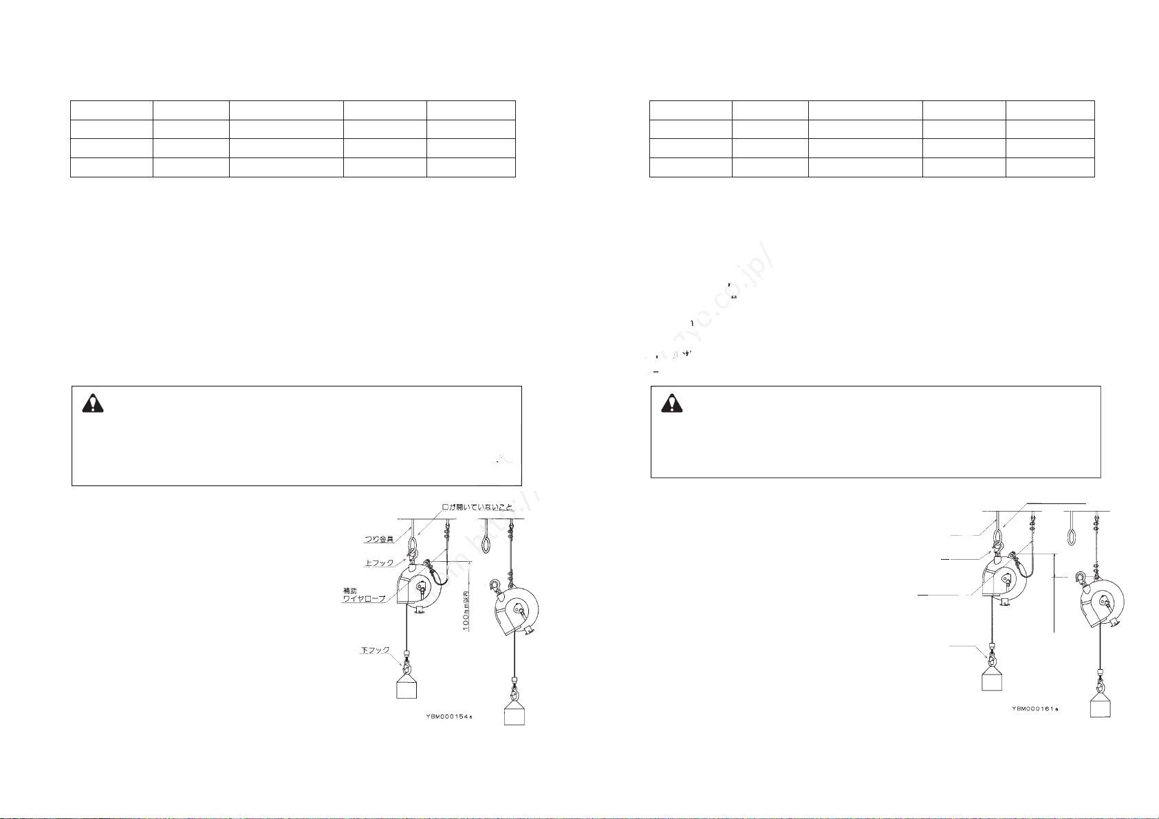
2.製品説明3.据え付け2−1.仕 様2−2.主な装置の説明3−1.バランサーの据え付け■使用条件 設置場所:一般屋内周囲温度:−10℃〜+50℃1)バランサーの支持部材(つり金具)は、2kN{200kgf}以上の強度を有するものを用意してください。留意:支持部材は、バランサーが動いても外れないよう図−1のように口の開いていないものを使用してください。2)バランサーの上フックを直接支持部材に取り付け、フックの外れ止め金具が閉じていることを確認してください。留意:バランサーが周囲のものにぶつからないように取り付けてください。またバランサーがお互いにぶつからないよう高低差をつけてください。3)バランサーが自由に動く事を確認してください。留意:上フックは固定しないでください。4)
バランサーに使用する補助ワイヤロープまたはチェーンは、2kN{200kgf}以上の強度を有するものを用意してください。
5)補助ワイヤロープまたはチェーンの一端を図−1のようにバランサー本体に取り付け、もう一方の端をバランサーの支持部材とは別の支持部材に取り付けてください。留意:補助ワイヤロープまたはチェーンには、バランサーが自由に動けるよう「タルミ」を設けてください。タルミは、もしバランサーの上フックや支持部材が破損し、バランサーが落下しても100mm以内で停止する長さにしてください。(図−1参照)ELF−3ELF−5ELF−91.5〜3.03.0〜5.05.0〜9.02.34.07.02.52.52.5約4.6約4.8約5.4型 式容量範囲(kg)
出荷時のセット容量(kg)
ストローク
(m)質量(kg)●バランサーを正しく据え付けてください。もし据え付けを誤ると、人身事故や財物損傷およびバランサーの損傷の原因となります。●バランサーには必ず補助ワイヤロープまたはチェーンを取り付けてください。万一、バランサーの上フックや支持部材(つり金具)が破損したとき、作業者を保護するために必要です。警告
-
3
-
図−1■落下防止装置スプリングが破断したとき、下フックに取り付けられた工具や機器が全ストローク落下することを防止する装置です。落下を未然に防止する装置ではありません。■ドラムロック装置
−
項目4−2「ドラムロックの操作方法」を参照ください。1/5回転間隔でドラムをロックすることができます。下のフックに取り付けられている工具や機器を外すとき(項目4−3参照)、およびワイヤロープを交換するとき(項目7参照)に使用します。2.Descriptionofproduct3.Installation2
-
1. Specifications
2
-
2. Main features
3
-
1. Balancer installation
■Working conditions Application area :Indoor and normal atmospheric conditions
Temperature range:
-
10゜C to +50゜C
■Fall prevention device
A mechanism to prevent the suspended tool/device from falling to the maximum cable travel in
case of spring breakage.
This mechanism can not prevent the tool/device from falling at all when the spring breaks.
■Drum lock (See Chapter 4
-
2 "Drum lock operation" )
A mechanism to lock the drum every 1/5 turns.
This mechanism is used when removing the suspended tool/device (See Chapter 4
-
3) or
replacing the wire rope (See Chapter 7) .
1) Prepare a fitting that can support at least 2kN{200kgf}.
NOTE: The fitting must have no opening as shown in
Fig. 1to prevent the balancer from disengaging
when it swings.
2) Attach the top hook of the balancer directly to the
fitting.
Check the latch is closed.
NOTE : Take care the balancer does not hit surrounding
objects. Make the mounting height different for
each balancer to avoid collision.
3) Check the top hook can swivel freely.
NOTE : Do not fasten the top hook to the balancer
body.
4) Prepare a secondary support cable or chain, used in
the balancer, that can support at least 2kN {200kgf}.
ELF
-
3
ELF
-
5
ELF
-
9
1.5〜3.0
3.0〜5.0
5.0〜9.0
2.3
4.0
7.0
2.5
2.5
2.5
Approx. 4.6
Approx. 4.8
Approx. 5.4
Model
Capacity range (kg)
Factory Preset Capacity (kg)
Cable travel(m)
Mass (kg)
●Install the balancer correctly.
Incorrect installation could cause personal injury or damage to the balancer or other equipment.
●Always attach a secondary support cable or chain.
It is required to protect worker (s) in case of failure of the top hook or the fitting.
WARNING
-
4
-
Fig. 1
5) As shown in Fig. 1, attach an end of the secondary support
cable or chain to balancer body, and attach the other end to a
separate fitting which does not support the balancer.
NOTE : Leave some slack in the secondary support cable or chain to
allow the balancer to rotate freely.
The slack must be a suitable length so that the balancer will stop within 100mm when
falling in case of failure of the top hook or the fitting (See Fig. 1) .
Noopening
FittingTophookSecondarysupportcableBottomhook
Within100mm
Copied
Copied
万一、バランサーの上フックや支持部材(つり金具)が破損したとき、作業者を保護するた万一、バランサーの上フックや支持部材(つり金具)が破損したとき、作業者を保護するた
digital
data
http://www.endo-kogyo.co.jp/
http://www.endo-kogyo.co.jp/
3.Installation3.Installation
33
--
1. Balancer installation1. Balancer installation
http://www.endo-kogyo.co.jp/
Fall prevention deviceFall prevention device
A mechanism to prevent the suspended tool/device from falling to the maximum cable travel in
A mechanism to prevent the suspended tool/device from falling to the maximum cable travel in
case of spring breakage.
case of spring breakage.
This mechanism can not prevent the tool/device from falling at all when the spring breaks.This mechanism can not prevent the tool/device from falling at all when the spring breaks.
Drum lock (See Chapter 4Drum lock (See Chapter 4
A mechanism to lock the drum every 1/5 turns.A mechanism to lock the drum every 1/5 turns.
This mechanism is used when removing the suspended tool/device (See Chapter 4This mechanism is used when removing the suspended tool/device (See Chapter 4
replacing the wire rope (See Chapter 7) .replacing the wire rope (See Chapter 7) .
http://www.endo-kogyo.co.jp/

4.使用方法3−2.工具、機器類の取り付けおよびスプリング張力の調整3−3.作業範囲(ストローク)の確認4−1.使用上の注意1)
あらかじめ、工具(機器)と付属品の総質量(重量)がバランサーの容量範囲内か確認してください。
2)工具を持ち上げてバランサーの下フックに取り付けます。ワイヤロープは引き出さないでください。留意:工具の質量(重量)がスプリングの張力を超えている場合は、工具が降下します。手を放さずゆっくりと下げてください。3)ウォームを回しスプリングの張力を調整します。ウォームを「+」側(右)に回すと張力が増加し、「−」側(左)に回すと張力が減少します。(図−2参照)4)バランスしていることを確認してください。留意:スプリングの張力が強すぎると、バランサー本体やワイヤロープ等が損傷する原因となります。1)ストロークの範囲内で作業が行えることを確認してください。2)もし必要なら、バランサーの取り付け高さを下げたり下フックと工具(機器)の間に適切なつり具を使用してください。空荷でワイヤロープを引き出さないでください。もし引き出したときに誤って手を放すと、ワイヤロープが急速に巻取られ人身事故の原因となります。警告スプリングの張力を最大容量より大きくすると、仕様ストロークがでないうえスプリングの寿命を短くします。また最小容量より小さくすると、落下防止装置が働き、工具(機器)の上下ができなくなります。注意ワイヤロープの引き出し過ぎは、バランサー損傷の原因となります。注意●ワイヤロープを引き出した状態で、バランサーの下フックから工具(機器)を取り外さないでください。●バランサーにつり下げた工具の真下に入らないでください。●バランサーの改造は行わないでください。警告
-
5
-
図−2Worm+(CW):Increase
-
(CCW):Decrease4. Use
3
-
2. Tool/device attachment and spring tension adjustment
3
-
3. Working stroke (cable travel) check
4
-
1. Safety instructions on use
1) Before attaching, check the mass (weight) of the complete tool/device, including all
accessories, is within the capacity range of the balancer.
2) Lift the complete tool/device up to the bottom hook and attach it.
Never pull the wire rope down to the tool/device.
NOTE: The suspended tool/device will drop down if the spring tension is not enough.
Lower the tool/device slowly by hand.
3) Adjust the spring tension by turning the worm with a wrench,
etc. Turn to the "+" side (clockwise) for increasing the spring tension, turn to the "
-
" side
(counterclockwise) for decreasing (See Fig. 2) .
4) Check the tool/device balanced.
NOTE: Over-tensioning could cause damage to the balancer body or the wire rope.
1) Check the cable travel is long enough for the application.
2) If necessary, lower the mounting height of the balancer or insert a suitable fitting between the
bottom hook and tool/device.
Never pull the wire rope when unloaded.
If the wire rope is released when extended with no load, it will snap back and could cause
personal injury.
WARNINGIf the spring tension is set over the maximum capacity, the balancer can not provide the
specified cable travel and the spring life will be shortened.
If the spring tension is set under the minimum capacity, the fall prevention device will operate
and stop the suspended tool device.
CAUTIONExtending the wire rope past the maximum cable travel could cause damage to the balancer.
CAUTION●Never remove tool/device from the bottom hook while the wire rope is extended.
●Never stand under the suspended tool/device.
●Never alter the balancer.
WARNING
-
6
-
Fig. 2
Copied
digital
data
from
from
http://www.endo-kogyo.co.jp/
http://www.endo-kogyo.co.jp/
http://www.endo-kogyo.co.jp/
Before attaching, check the mass
Before attaching, check the mass
accessories, is within the capacity range of the balancer.
accessories, is within the capacity range of the balancer.
2) Lift the complete tool/device up to the bottom hook and attach it.2) Lift the complete tool/device up to the bottom hook and attach it.
Never pull the wire rope down to the tool/device.Never pull the wire rope down to the tool/device.
NOTE
NOTE
: The suspended tool/device will drop down if the spring tension is not enough.: The suspended tool/device will drop down if the spring tension is not enough.
Lower the tool/device slowly by hand.Lower the tool/device slowly by hand.
3) Adjust the spring tension by turning the worm with a wrench,3) Adjust the spring tension by turning the worm with a wrench,
etc. Turn to the "+" side (clockwise) for increasing the spring tension, turn to the "etc. Turn to the "+" side (clockwise) for increasing the spring tension, turn to the "
(counterclockwise) for decreasing (See Fig. 2) .(counterclockwise) for decreasing (See Fig. 2) .
4) Check the tool/device balanced.4) Check the tool/device balanced.
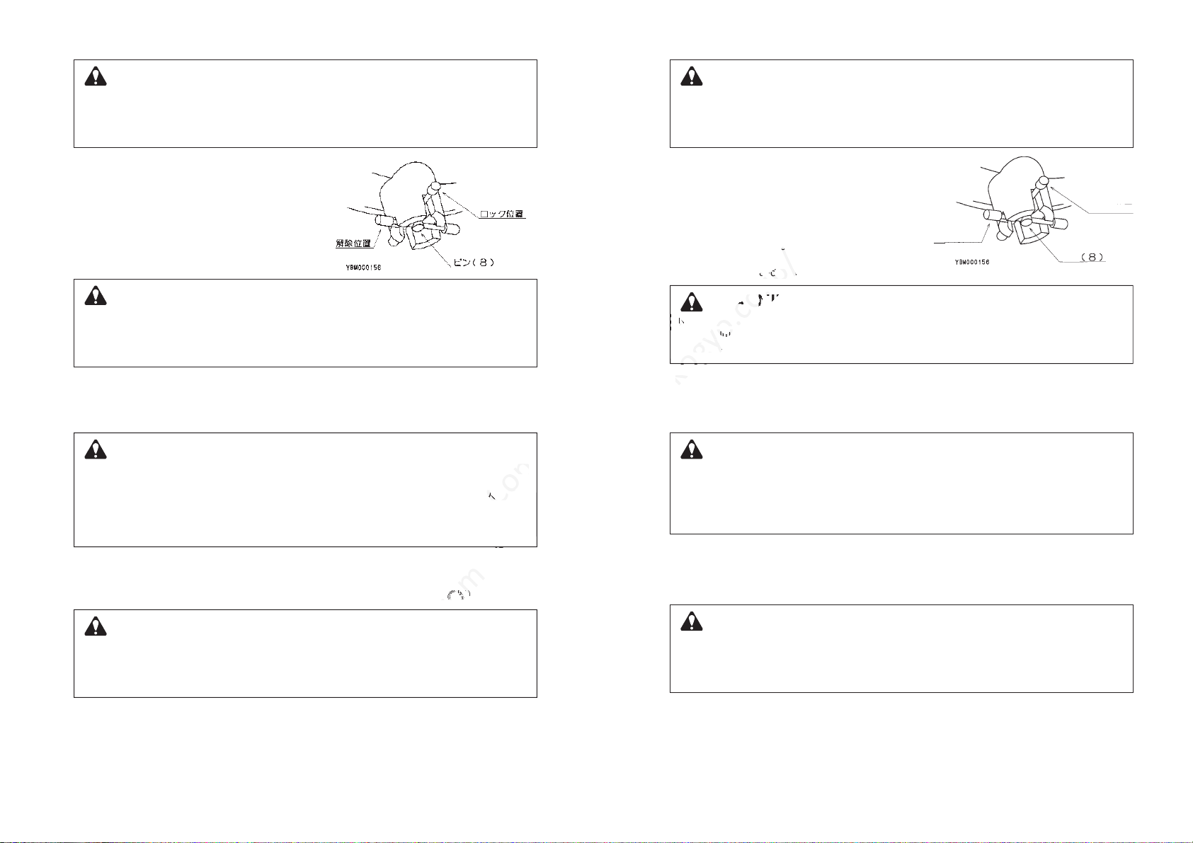
1)ピン(8)を引き上げ、左に回してロック位置にします。(図−3参照)2)工具(機器)を上下に動かします。ピン(8)がドラムの溝に挿入され、ドラムがロックされます。3)再び、工具を上下に動かし、ドラムが確実にロックされていることを確認します。4)工具を外すことができます。5)ドラムロックを解除する前に、工具(機器)を外したときは必ず工具を取り付けてください。取り付ける工具の質量(重量)は外した工具の質量とほぼ同じでなければなりません。6)ピン(8)を引き上げるとドラムロックが解除されます。ピンがロック位置に戻らないよう解除位置(右)に回してください。●必ず容量範囲内で使用してください。●スプリングの張力を調整してから使用してください。●ワイヤロープをストローク以上に引き出さないでください。●ワイヤロープの斜め引きはしないでください。注意ドラムが確実にロックされていることを確認するまで、下フックに取り付けられている工具(機器)は外さないでください。もしドラムのロックが不十分だと、作業中にドラムロックが外れ、ワイヤロープが急速に巻取られ人身事故の原因となります。警告空荷のときや、交換した工具(機器)の質量(重量)が異なるときは、ドラムロックを解除しないでください。もし解除すると、解除と同時にワイヤロープが急速に巻取られたり、工具が降下し人身事故の原因となります。ドラムロックの解除は、工具を取り付け、スプリング張力を調整してから行ってください。これは安全作業上重要です。警告4−2.ドラムロックの操作方法■方法1−ドラムロックを使用する場合1)項目4−2「ドラムロックの操作方法」に従ってドラムをロックし、工具(機器)を外します。2)あらかじめ、交換する工具(機器)と付属品の総質量(重量)がバランサーの容量範囲内か確認してください。3)工具を下フックに取り付けます。4)工具を保持したまま、ドラムロックを解除した後、スプリング張力の調整を行いバランスしていることを確認してください。留意:スプリングの張力が強すぎると、バランサー本体やワイヤロープ等が損傷する原因となります。4−3.工具、機器類の交換工具(機器)を上下に動かし、ドラムが確実にロックされていることを確認するまで工具を外さないでください。もしドラムのロックが不十分だと、作業中にドラムロックが外れ、ワイヤロープが急速に巻取られ人身事故の原因となります。警告
-
7
-
図−3LockpositionPinReleaseposition1) Pull Pin (8) Up and turn it clockwise to place in the
lock position (See Fig. 3) .
2) Move the suspended tool/device upward or
downward until Pin (8) enters the slot/hole in the
drum and the drum becomes locked.
3) Move the tool/device again to check the drum is
locked securely.
4) Remove the tool/device from the bottom hook.
5) Before releasing the drum lock, attach a new tool/device if the old one has been removed.
The new tool/device must have almost the same mass (weight) as the old one.
6) Release the drum lock by pulling Pin (8) up.
Turn Pin (8) clockwise and place it in the release position.
●Always use within the capacity range of the balancer.
●Always adjust the spring tension before use.
●Do not extend the wire rope past the maximum cable travel.
●Do not pull the wire rope at an angle.
CAUTIONNever remove the suspended tool/device before checking the drum is locked securely.
If the drum is not locked securely, the drum lock could be released allowing the wire rope to
snap back, possibly causing personal injury.
WARNINGNever release the drum lock when the balancer is unloaded or the new tool/device has a different
mass (weight) to the old one.
If released, the wire rope will snap back or the tool/device could drop down respectively, possibly
causing personal injury. Always release the drum lock after arranging the tension of spring and
tool/device. This is important factor for safety.
WARNING4
-
2. Drum lock operation
■Method 1
-
With drum lock.
1)
Lock the drum according to Chapter 4
-
2
"
Drum lock operation
"
Remove the suspended tool/device.
2) Before attaching, check the mass (weight) of the new complete tool/device, including all
accessories. is within the capacity range of the balancer.
3) Attach the new complete tool/device to the bottom hook.
4) After relesing the drum lock, adjust the spring tension again and check the tool/device is
balanced.
NOTE: Over-tensioning could cause damage to the balancer body or the wire rope.
4
-
3. Tool/device replacement
Move the tool/device upward and downward to check the drum is locked securely.
Never remove the tool/device before checking this.
If the drum is not locked securely, the drum lock could be released allowing the wire rope to
snap back, possibly causing personal injury.
WARNING
-
8
-
Fig. 3
Copied
Copied
空荷のときや、交換した工具(機器)の質量(重量)が異なるときは、ドラムロックを解除空荷のときや、交換した工具(機器)の質量(重量)が異なるときは、ドラムロックを解除
もし解除すると、解除と同時にワイヤロープが急速に巻取られたり、工具が降下し人身事故
もし解除すると、解除と同時にワイヤロープが急速に巻取られたり、工具が降下し人身事故
digital
data
data
Never remove the suspended tool/device before checking the drum is locked securely.
Never remove the suspended tool/device before checking the drum is locked securely.
from
1)項目4−2「ドラムロックの操作方法」に従ってドラムをロックし、工具(機器)を外します。1)項目4−2「ドラムロックの操作方法」に従ってドラムをロックし、工具(機器)を外します。
from
http://www.endo-kogyo.co.jp/
http://www.endo-kogyo.co.jp/
ドラムロックの解除は、工具を取り付け、スプリング張力を調整してから行ってください。
ドラムロックの解除は、工具を取り付け、スプリング張力を調整してから行ってください。
5) Before releasing the drum lock, attach a new tool/device if the old one has been removed.5) Before releasing the drum lock, attach a new tool/device if the old one has been removed.
http://www.endo-kogyo.co.jp/
Move the tool/device again to check the drum is
Move the tool/device again to check the drum is
locked securely.
4) Remove the tool/device from the bottom hook.
4) Remove the tool/device from the bottom hook.
http://www.endo-kogyo.co.jp/
Never remove the suspended tool/device before checking the drum is locked securely.Never remove the suspended tool/device before checking the drum is locked securely.
If the drum is not locked securely, the drum lock could be released allowing the wire rope toIf the drum is not locked securely, the drum lock could be released allowing the wire rope to
snap back, possibly causing personal injury.snap back, possibly causing personal injury.
WARNINGWARNING

1)工具(機器)を持ち上げ、ドラムにワイヤロープをすべて巻取らせた状態で工具を外します。2)項目3−2「工具、機器類の取り付けおよびスプリング張力の調整」に従って工具を取り付けます。●空荷でドラムロックを解除しないでください。もし解除すると、解除と同時にワイヤロープが急速に巻取られ、人身事故の原因となります。●交換した工具(機器)の質量(重量)が異なるときは、工具を持ったままドラムロックを解除してください。もし工具を持たずにドラムロックを解除すると、工具が急速に上昇したり、降下し人身事故の原因となります。警告ワイヤロープを引き出した状態で工具(機器)を外さないでください。もし工具を外すと、ワイヤロープが急速に巻取られ人身事故の原因となります。警告●使用中に異常を感じたときは、ただちに使用を中止し適正な処置を行ってください。●不具合の原因が判明するまで、下フックに取り付けられている工具(機器)は取り外さないでください。もし工具を外すと、ワイヤロープが急速に巻取られ人身事故の原因となります。警告■ワイヤロープがドラムとケースの間に挟まれている場合1)工具(機器)を取り付けた状態でワイヤロープを強く引き出します。留意:引き出した後ワイヤロープを点検し、損傷している場合は交換してください。■方法2−ドラムロックを使用しない場合不用意な作業は、人身事故やバランサーに余分な損傷を与える原因となります。注意して作業してください。注意
-
9
-
5.一般的な不具合とその処置不 具 合原 因処 置●ワイヤロープの引き出しおよび巻き取りができない。●ドラムロックが作動している。●ワイヤロープがドラムの溝から外れケースとドラムの間に挟まれた。●スプリングが破断した。●ドラムロックを解除する。項目4−2参照●ワイヤロープをドラムの溝へ戻す。項目5−2参照●スプリングを交換する。項目8参照●ワイヤロープの引き出しができない。●スプリング張力を強めすぎてスプリングが巻締まった。●スプリング張力を弱めすぎて落下防止装置が作動した。●スプリングの張力を弱める。項目3−2参照●落下防止装置を解除する。項目5−2参照この例にない不具合が起こったときは、販売店または当社に問い合わせください。5−2.処置(分解図/頁−21参照)5−1.不具合とその原因1) Lift then remove the suspended tool/device when the wire rope is fully retracted.
2) Attach a new tool/device according to Chapter 3
-
2
"Tool/device attachment and spring tension adjustment".
●Never release the drum lock when the balancer is unloaded.
If released, the wire rope will snap back, possibly causing personal injury.
●Always hold the suspended new tool/device by hand when releasing the drum lock, if the
new tool/device has a different mass (weight) to the old one.
Otherwise, the tool/device could rise up or drop down suddenly, possibly causing personal injury.
WARNINGNever remove the suspended tool/device while the wire rope is extended.
If removed, the wire rope will snap back and could cause personal injury.
WARNING■Method 2
-
Without drum lock
-
10
-
●If a malfunction occurs during operation, stop operation immediately and take the necessary
steps to rectify the problem.
●Never remove the suspended tool/device before identifying causes of the malfunction.
If removed, the wire rope will snap back and could cause personal injury.
WARNING■When the wire rope is caught between drum and casing.
1) Release Wire rope by jerking it strongly while the tool/device is suspended.
NOTE: After jerking, check wire rope and replace if damaged.
Careless repairs can cause personal injury or damage to the balancer. Therefore, be careful
but thorough when making repairs.
CAUTION5. Troubleshooting
Ma l f un ct i on C a u s e S o l u t i o n
●Wire rope can not be pulled
out and retracted. ●Drum lock is engaged.
●Wire rope has slipped off
from the drum groove and is
caught between drum and
casing.
●Spring has broken. ●Release drum lock.
See Chapter 4
-
2.
●Return wire rope to the
drum groove.
See Chapter 5
-
2.
●Replace spring.
See Chapter 8.
●Wire rope can not be pulled
out. ●
Spring is fully wound up because
of over-tensioning.
●
Fall prevention device is engaged
because the spring tension is set
under the minimum capacity.
●Release spring.
See Chapter 3
-
2.
●Release fall
prevention device.
See Chapter 5
-
2.
Contact your dealer or us if a malfunction not listed above occurs.
5
-
2. Solutions (Refer to the disassembly drawings on pages 21)
5
-
1. Common malfunctions and their causes
Copied
Copied
Copied
Copied
●ドラムロックを解除する。●ドラムロックを解除する。
●ワイヤロープをドラムの溝へ
●ワイヤロープをドラムの溝へ
digital
data
data
data
5. Troubleshooting
5. Troubleshooting
from
from
from
●スプリングの張力を弱める。
●スプリングの張力を弱める。
項目3−2参照項目3−2参照
●落下防止装置を解除する。●落下防止装置を解除する。
項目5−2参照
項目5−2参照
http://www.endo-kogyo.co.jp/
http://www.endo-kogyo.co.jp/
http://www.endo-kogyo.co.jp/
●ワイヤロープをドラムの溝へ●ワイヤロープをドラムの溝へ
●スプリングを交換する。●スプリングを交換する。
●スプリングの張力を弱める。
●スプリングの張力を弱める。
1) Lift then remove the suspended tool/device when the wire rope is fully retracted.
1) Lift then remove the suspended tool/device when the wire rope is fully retracted.
2) Attach a new tool/device according to Chapter 3
2) Attach a new tool/device according to Chapter 3
"Tool/device attachment and spring tension adjustment"."Tool/device attachment and spring tension adjustment".
http://www.endo-kogyo.co.jp/
http://www.endo-kogyo.co.jp/
●●
If a malfunction occurs during operation, stop operation immediately and take the necessaryIf a malfunction occurs during operation, stop operation immediately and take the necessary
steps to rectify the problem.steps to rectify the problem.
●●
WARNINGWARNING
http://www.endo-kogyo.co.jp/
http://www.endo-kogyo.co.jp/
http://www.endo-kogyo.co.jp/
5. Troubleshooting5. Troubleshooting
2)引き出しができない場合は、ウォーム(42)の先端よりE形止メ輪(43)を外します。3)ウォーム(42)の先端よりE形止メ輪(43)を外します。ウォームが抜け始めるまでウォームを「−」側(左)に回し、スプリングの張力をゼロにします。留意:ワイヤロープを引っ張りスプリングの張力がゼロになっていることを確認します。4)下フック(30)から工具を外し、バランサーを支持部材より取り外します。5)ナベ小ネジ(41)を外し、カバー(40)を取り外します。6)ワイヤロープ(28)をドラム(16)の溝に戻します。留意:ワイヤロープを点検し、損傷している場合は交換してください。7)カバー(40)を組み付けます。8)ウォーム(42)を組み込み、E形止メ輪(43)を取り付けます。9)ウォーム(42)を「+」側(右)に回し、スプリング(18)を巻きます。注意:ウォームを回すと、ワイヤロープ(28)がドラム(16)に巻取られます。ワイヤロープがドラムの溝から外れないよう注意してください。ワイヤロープがすべてドラムに巻取られてから、さらにウォームを項目8「スプリングの交換」の表−1に示す回数を回してください。■スプリングの張力を弱めすぎて落下防止装置が作動した場合工具(機器)を取り付けた状態で、ウォーム(42)を「+」側(右)に回して張力を増加させると落下防止装置が解除されます。下フックに取り付けられている工具(機器)は取り外さないでください。もし工具を取り外した状態でウォームを回すと、落下防止装置が解除されると同時にワイヤロープが急速に巻取られ人身事故の原因となります。警告
-
11
-
2) If Wire rope cannot be released by jerking, disassembly is required. Remove Retaining ring
(43) from Worm (42) .
3) Remove Retaining ring (43) from Worm (42) .
Release all spring tension by turning Worm (42) to the "
-
" side (counterclockwise) until Worm
can almost be removed.
NOTE : Check the spring tension by pulling Wire rope.
4) Remove the tool/device from bottom Hook (30) , and remove the balancer from the fitting.
5) Loosen Screws (41) and remove Cover (40) .
6) Return Wire rope (28) to the groove of Drum (16) .
NOTE : Check Wire rope and replace if damaged.
7) Install Cover (40) .
8) Install Worm (42) , and attach Retaining ring (43) .
9) Wind Spring (18) by turning Worm (42) to the "+" side (clockwise) .
CAUTION : While turning Worm, Wire rope (28) will be retracted into Drum (16) .
Pay attention Wire rope does not slip out from the drum groove.
After Wire rope is fully retracted, turn Worm by the number of turns shown in
Table 1 of「Spring replacement」.
■When the fall prevention device has engaged because the spring tension is set under the
minimum capacity.
While suspending the tool/device, turn Worm (42) to the "+" side (clockwise) to increase the
spring tension until the fall prevention device disengages.
Never remove the suspended tool/device.
If removed, the wire rope will snap back the moment the fall prevention device disengages and
could cause personal injury.
WARNING
-
12
-
Copied
digital
data
from
http://www.endo-kogyo.co.jp/
While turning Worm, Wire rope (28) will be retracted into Drum
While turning Worm, Wire rope (28) will be retracted into Drum
Pay
attention Wire rope does not slip out from the drum groove.
attention Wire rope does not slip out from the drum groove.
After Wire rope is fully retracted, turn Worm by the number of turns shown in
After Wire rope is fully retracted, turn Worm by the number of turns shown in
Table 1 ofTable 1 of
hen the fall prevention device has engaged because the spring tension is set under thehen the fall prevention device has engaged because the spring tension is set under the
inimum capacity.inimum capacity.
While suspending the tool/device, turn Worm (42) to the "+" side (clockwise) to increase theWhile suspending the tool/device, turn Worm (42) to the "+" side (clockwise) to increase the
spring tension until the fall prevention device disengages.spring tension until the fall prevention device disengages.
http://www.endo-kogyo.co.jp/
Never remove the suspended tool/device.
http://www.endo-kogyo.co.jp/
http://www.endo-kogyo.co.jp/
http://www.endo-kogyo.co.jp/

6.点検定期的にバランサーを点検し、摩耗したり、損傷している部品は交換してください。警告部品を交換する場合は純正部品を使用してください。注意■少なくとも毎月1回以上は点検をして、不具合な箇所は適正な処置を行ってください。使用環境の悪い場所や使用頻度の多いときは、点検の間隔を短くしてください。(図−4参照)■上フック使用限界■下フック使用限界■ワイヤロープ使用限界基準寸法:3.0mm限界寸法:2.7mm
-
13
-
44.0mm11.7mm15.5mm1.5mm41.0mm8.0mm
16.5mm
YBM000211図−4There must be no kinks.
1 pitch
Allowable number of broken
wires in 1 pitch is 11
6. Inspections
Periodically inspect the balancer, and replace any Worm or damaged parts.
WARNINGAlways use genuine parts for replacement.
CAUTION■Inspect the balancer at least once a month.
Correct and repair any problems which are detected.
Make the inspection interval shorter when operating frequently or under hostile environments.
(See Fig. 4)
■Service limit of top hook
■Service limit of bottom hook
■Service limit of wire rope
Standard dimension: 3.0mm
Limit dimension : 2.7mm
-
14
-
44.0mm11.7mm15.5mm1.5mm41.0mm8.0mm
16.5mm
YBM000211Fig. 4
●Is there any
wear or damage? ●Is there any
wear or damage?
●Move upward during
inspection.
Top hook
Fitting
Latch
●Is there any
deformation?
Latch
Bottom hook
Thimble.Bottom hook
Buffer
Collar
●Is there any
deformation?
Can hook
swivel smoothly?
Casing,Drum
●Is there any
wear or damage?
Wire guide
●Are there any wear
or cracks?
●Are screws loose?
Wire rope
●Is there any damage?
Check for wire breakage or
damage near the lock tube.
Is there any wear or damage?
●Is there any wear
or cracks?
Are screws loose?
Secondary support
cable(chain)
●Is there any damage?
●Are bolts loose?
digital
data
from
http://www.endo-kogyo.co.jp/
Service limit of top hook
Service limit of top hook
http://www.endo-kogyo.co.jp/
11.7mm

7.ワイヤロープの交換8.スプリングの交換1)工具(機器)を引き下げ、ワイヤロープをすべて引き出します。2)ドラムに取り付いている座金組込ミ六角穴付ボルト(39)の位置を図−5で示すように窓から見える位置に合わせ、ドラムロックでドラムをロックします。項目4−2「ドラムロックの操作方法」を参照ください。3)工具を上下に動かし、ドラムが確実にロックされていることを確認してから工具を外します。分解図(頁−21)を参照のうえ、次の手順に従って行ってください。1)A.スプリングが破断している場合工具を下フック(30)より外します。B.スプリングが破断していない場合工具を持ち上げて、ドラム(16)にワイヤロープ(28)をすべて巻取らせた状態で工具を下フック(30)より外します。2)バランサーを支持部材より取り外し、地上に降ろします。3)ウォーム(42)の先端よりE形止メ輪(43)を外します。ウォームが抜け始めるまでウォームを「−」側(左)に回し、スプリングの張力をゼロにします。留意:ワイヤロープを引っ張りスプリングの張力がゼロになっていることを確認します。スプリングは交換時以外、ドラムより取り出さないでください。スプリング交換時は、Oリングも同時に交換してください。ドラムが確実にロックされていることを確認するまで工具(機器)を外さないでください。もしドラムのロックが不十分だと、作業中にドラムロックが外れ、ワイヤロープが急速に巻取られたりドラムが急に回転し人身事故の原因となります。警告工具(機器)を取り付けるまでドラムロックを解除しないでください。もし解除すると、ワイヤロープが急速に巻取られ人身事故の原因となります。警告●スプリングは非常に危険です。取り扱いは十分注意してください。●ドラムより取り出すとき、スプリングの中心部分は絶対に引き出さないでください。もし引き出すと、スプリングが急激に広がり人身事故の原因となります。警告
-
15
-
4)バランサーを支持部材より取り外し、地上に降ろします。5)座金組込ミ六角穴付ボルト(39)および、ブッシュ(38)を外し、古いワイヤロープをドラムより取り外します。項目4−2「ドラムロックの操作方法」を参照ください。6)
新しいワイヤロープをワイヤロープ挿入穴Aより差し込み、ブッシュ(38)をワイヤロープのロック管にはめ込みドラムの溝に入れ、座金組込ミ六角穴付ボルト(39)をドラムに固定する。
7)バランサーを支持部材に取り付けます。項目3−1「バランサーの据え付け」を参照ください。8)下フックに外した工具を再び取り付け、ドラムロックを解除します。図−57. Wire rope replacement
8. Spring replacement
1) Lower the tool/device, extending Wire rope to the
maximum cable travel.
2) Position Screw (39) at the casing opening as
shown in Fig.5, and engage the drum lock.
See. Chapter 4
-
2 "Drum lock operation".
3) Move the tool/device upward and downward to
check Drum is locked securely. Remove the
tool/device from bottom Hook.
Referring to the disassembly drawing
(
on pages 21
)
, replace the spring using the following procedure.
1) A.When the spring has broken;
Remove the tool/device from bottom Hook (30) .
B.When the spring has not broken;
Lift then remove the tool/device from bottom hook (30) when Wire rope (28) is fully
retracted into Drum (16) .
2) Remove the balancer from the fitting and place on the floor.
3) Remove Retaining ring (43) from Worm(42) . Release all spring tension by
turning Worm (42) to the "
-
" side (counterclockwise) until Worm can almost be removed.
NOTE: Check the spring tension by pulling Wire rope.
Never remove the spring from the drum unless the replacement is required.
Replace O-ring and the spring at the same time.
Never remove the suspended tool/device before
checking Drum is locked securely.
If Drum is not locked securely, the Drum is not
lock could be released allowing Wire rope to
snap back or Drum to rotate suddenly, possibly
causing personal injury.
WARNINGNever release the drum lock before attaching the tool/device.
If released, Wire rope will snap back and could cause personal injury.
WARNING●The spring is extremely dangerous. Be careful when handling the spring.
●Never pull the center of the spring when removing the spring from the drum. If pulled, the
spring will expand explosively and cause personal injury.
WARNING
-
16
-
4) Remove the balancer from the fitting and place
on the floor.
5) Remove Screw (39) , and Bushing (38) . Then remove old Wire rope
from Drum. See Chapter 4
-
2 "Drum lock operation".
6) Insert new Wire rope from the A
-
side, attach Bushing (38) to the Wire rope,and then pass it
through Drum and fasten with Screw (39) .
7) Install the balancer on the fitting. See Chapter 3
-
1 "Balancer installation".
8) Attach the tool/device to bottom Hook, and release the drum lock.
Fig. 5
Remove
Screw(39)
Wire rope(28)
Wire rope entrance hole A
Buffer(37)
Collar(36)
Bottom hook(30)
Lock
position
Release
position
Pin(8)
Bushing(38)
Attach Bushing
to Wire rope
Window
Copied
Copied
digital
data
4) Remove the balancer from the fitting and place
4) Remove the balancer from the fitting and place
from
from
●ドラムより取り出すとき、スプリングの中心部分は絶対に引き出さないでください。
●ドラムより取り出すとき、スプリングの中心部分は絶対に引き出さないでください。
http://www.endo-kogyo.co.jp/
http://www.endo-kogyo.co.jp/
http://www.endo-kogyo.co.jp/
If Drum is not locked securely, the Drum is not
If Drum is not locked securely, the Drum is not
lock could be released allowing Wire rope to
lock could be released allowing Wire rope to
snap back or Drum to rotate suddenly, possibly
snap back or Drum to rotate suddenly, possibly
causing personal injury.causing personal injury.
4) Remove the balancer from the fitting and place4) Remove the balancer from the fitting and place
on the floor.on the floor.
5) Remove Screw (39) , and Bushing (38) . Then remove old Wire rope5) Remove Screw (39) , and Bushing (38) . Then remove old Wire rope
from Drum. See Chapter 4from Drum. See Chapter 4
6) Insert new Wire rope from the A6) Insert new Wire rope from the A
through Drum and fasten with Screw (39) .
7) Install the balancer on the fitting. See Chapter 3
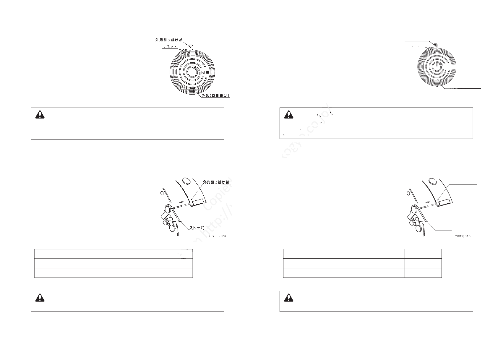
4)さらにウォーム(42)を左に回して抜き取ります。5)座金組込ミ六角穴付ボルト(39)、ブッシュ(38)およびワイヤロープ(28)をドラム(16)より取り外します。6)ナベ小ネジ(41)を外し、カバー(40)を取り外します。7)ドラム(16)とスピンドル(14)を一体でケース(1)より取り外し、スピンドル(14)をドラムより抜き取ります。8)ナベ小ネジ(26)を外し、カバー(20)を取り外します。9)スプリング(18)の破断位置およびリベットの状態を確認します。スプリングが外側の密着部分で破断している場合、およびリベットが破損している場合は、再びカバー(20)を取り付け、販売店にご相談ください。(図−6参照)更に、スプリング破断時にストッパ(23)およびリベット(24)を点検し、損傷している場合は交換してください。10)ドラム(16)からスピンドル(14)を抜き取り、スプリング(18)を取り出します。11)Oリング(15)をスピンドル(14)から取り外します。12)組み付けは分解の逆手順で行い、次の点に注意してください。●ケース(1)にスピンドル(14)を組み付けた後、新しいOリング(15)の表面にグリースを塗布してください。更に、スプリング上面にはグリースを塗布してください。●カバー(20)をドラム(16)に組み付けるときは、ストッパ(23)がスプリング(18)の外周の引っ掛け部に入るよう組み付けてください。(図−7参照)
組み付け後、ストッパが楽に動くことを確認してください。
13)ウォーム(42)を「+」側(右)に回し、スプリング(18)を巻きます。留意:ウォームを回すと、ワイヤロープ(28)がドラム(16)に巻取られます。ワイヤロープがドラムの溝から外れないよう注意してください。ワイヤロープがすべてドラムに巻取られてから、さらにウォームを表−1に示す回数を回してください。スプリングが外周の密着部分で破断している場合、およびスプリングのリベットが破損しているときは、絶対にドラムから取り出さないでください。(図−6参照)もしスプリングを取り出すと、スプリングが急激に広がり人身事故の原因となります。警告型 式
ウォーム回転数中間容量までの目安値約902.3kg約904.0kg約857.0kg
ELF−3
ELF
−
5ELF
−
9
表−19.スプリングの破棄手荒な取り扱いやスプリング中心部を引っ張ると、スプリングが急激に広がり危険な状態になることを処理業者に連絡してください。スプリングは破断しても部分的に張力が残っているため、非常に危険です。警告
-
17
-
図−7図−64) Turn Worm (42) further and remove it.
5) Remove Screw (39) , Bushing (38) and the
Wire rope (28) from Drum (16) .
6) Loosen Screws (41) and remove Cover (40) .
7) Remove Drum (16) and Spindle (14) together from
Casing (1) . The remove Spindle (14) from Drum (16) .
8) Loosen Screws (26) and remove Cover (20) from Drum (16) .
9) Check where is the broken portion of spring (18) .
Check that the rivet of Spring is not broken.
If Spring is broken near the outer periphery where is
no space between each turn or the rivet of Spring (18) is broken
(See Fig.6) , stop the replacement work. Reassemble Cover (20)
and contact the dealer.
Check Stopper (23) and Rivet (24) when spring breakage. Replace them if they are broken.
10) Remove Spindle (14) from Drum (16) and remove Spring (18) .
11) Remove O-ring (15) from Spindle (14) .
12) Reassemble in reverse order.
●First install Spindle (14) in Casing (1) , then lubricate O-ring (15)
with grease. And lubricate Spring with grease.
●When installing Cover (20) to Drum (16) , place
Stopper(23) in outer edge of Spring (18) . (See Fig. 7)
Cheek Stopper can move smoothly after installing.
13) Wind Spring (18) by turning Worm (42) to the "+" side
(clockwise) .
NOTE: While turning Worm, Wire rope (28) will be retracted
into Drum (16) . Pay attention Wire rope does not
slip out from the drum groove. After Wire rope is
fully retracted, turn Worm by the number of turns
shown in Table 1.
Never remove spring from the Drum when spring is broken near the outer periphery or the rivet
of Spring is broken (See Fig. 6) .
If removed, the spring will expand explosively and cause personal injury.
WARNINGModel
Number of turns
Number above are for
the middle value of
the capacity range.
Approx. 90
2.3kg
Approx. 90
4.0kg
Approx. 85
7.0kg
ELF−3
ELF
−
5 ELF
−
9
Table 1
9. Spring disposal
Give a warning to disposal companies that the spring will expand explosively and cause danger if
the spring is treated roughly or the center of the spring is pulled.
The spring is dangerous due to remaining tension even if it is broken.
WARNING
-
18
-
Fig. 7
Outer edge
Stopper
Fig. 6
Outer edge
Rivet
Inside
Near the outer
periphery
Copied
digital
data
data
If removed, the spring will expand explosively and cause personal injury.
If removed, the spring will expand explosively and cause personal injury.
from
from
from
−
−
99
http://www.endo-kogyo.co.jp/
10) Remove Spindle (14) from Drum (16) and remove Spring (1810) Remove Spindle (14) from Drum (16) and remove Spring (18
11) Remove O-ring (15) from Spindle (14) .11) Remove O-ring (15) from Spindle (14) .
12) Reassemble in reverse order.12) Reassemble in reverse order.
http://www.endo-kogyo.co.jp/
http://www.endo-kogyo.co.jp/
Check Stopper (23) and Rivet (24) when spring breakage. Replace them if they are broken.
Check Stopper (23) and Rivet (24) when spring breakage. Replace them if they are broken.
http://www.endo-kogyo.co.jp/
Never remove spring from the Drum when spring is broken near the outer periphery or the rivetNever remove spring from the Drum when spring is broken near the outer periphery or the rivet
of Spring is broken (See Fig. 6) .of Spring is broken (See Fig. 6) .
If removed, the spring will expand explosively and cause personal injury.If removed, the spring will expand explosively and cause personal injury.
WARNING
WARNING
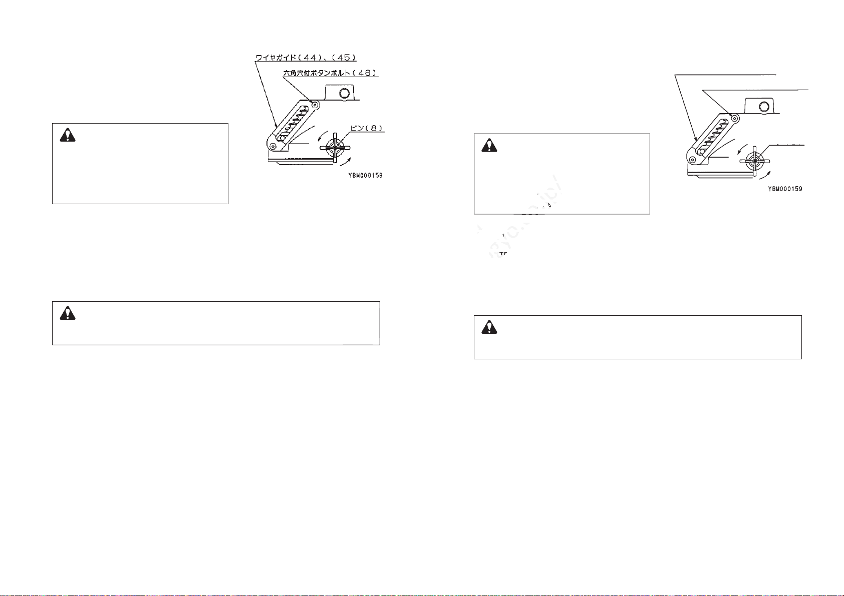
10.ワイヤガイドの交換1)ワイヤガイド(44)、(45)の交換作業が可能な位置までワイヤロープを引き出し、ドラムロックでドラムをロックします。(図−8参照)項目4−2「ドラムロックの操作方法」を参照ください。2)工具(機器)を上下に動かし、ドラムが確実にロックされていることを確認してから工具を外します。ドラムが確実にロックされていることを確認するまで、工具(機器)を外さないでください。もしドラムのロックが不十分だと、作業中にドラムロックが外れ、ワイヤロープが急速に巻取られたり、ドラムが急に回転し人身事故の原因となります。警告3)バランサーを支持部材より取り外し、地上に降ろします。4)六角穴付ボタンボルト(46)を外し、古いワイヤガイドを外します。5)新しいワイヤガイド(44)、(45)を取り付けます。留意:六角穴付ボタンボルト(46)はゆるみ防止処理されていますので、常に新しいものを使用してください。六角穴付ボタンボルトを2.8〜3.0N・m{0.28〜0.3kgf・m}のトルクで締め付けます。6)バランサーを支持部材に取り付けます。項目3−1「バランサーの据え付け」を参照ください。7)下フックに外した工具を再び取り付け、ドラムロックを解除します。工具(機器)を取り付けるまでドラムロックは解除しないでください。もし解除すると、ワイヤロープが急激に巻取られ人身事故の原因となります。警告
-
19
-
図−810. Wire guide replacement
1) Pull out the wire rope to the position which wire guide
replacement is available and lock drum with drum lock
device (refer to Fig. 8)
Refer to Chapter 4
-
2 "Drum lock operation".
2) After confirming that drum lock is surely on work,
moving a suspended tool up and
down, take off a suspended tool.
Never remove the suspended tool/device before
checking Drum is locked securely.
If Drum is not locked securely, the drum lock
could be released allowing Wire rope to snap or
Drum to rotate suddenly,
possibly causing personal injury.
WARNING3) Remove the balancer from a fitting and place on the floor.
4) Remove Hex. Socket button bolts (46) are old wire guide from casing.
5) Fix new wire guide (44), (45) .
NOTE: Hex. Socket button bolts (46) are sealed against looseness.
Always replace old ones with new ones when they are removed.
Tighten the hex. Socket bolts with torque of 2.8〜3.0N・m {0.28〜0.3kgf・m}.
6) Mount the balancer on a fitting.
Reter to Chapter 3
-
1 "Balancer Installation".
7) Attach the tool/device to bottom Hook, and release the drum lock.
Never release the drum lock before attaching the tool/device.
If released, Wire rope will snap back and could cause personal injury.
WARNINGWire guide(44),(45)Hex. socket button(46)Pin(8)Fig. 8
-
20
-
Copied
Copied
digital
data
3) Remove the balancer from a fitting and place on the floor.
3) Remove the balancer from a fitting and place on the floor.
4) Remove Hex. Socket button bolts (46) are old wire guide from casing.4) Remove Hex. Socket button bolts (46) are old wire guide from casing.
from
http://www.endo-kogyo.co.jp/
http://www.endo-kogyo.co.jp/
If Drum is not locked securely, the drum lock
If Drum is not locked securely, the drum lock
could be released allowing Wire rope to snap or
could be released allowing Wire rope to snap or
Drum to rotate suddenly,Drum to rotate suddenly,
possibly causing personal injury.possibly causing personal injury.
3) Remove the balancer from a fitting and place on the floor.3) Remove the balancer from a fitting and place on the floor.
4) Remove Hex. Socket button bolts (46) are old wire guide from casing.4) Remove Hex. Socket button bolts (46) are old wire guide from casing.
5) Fix new wire guide (44), (455) Fix new wire guide (44), (45
NOTENOTE
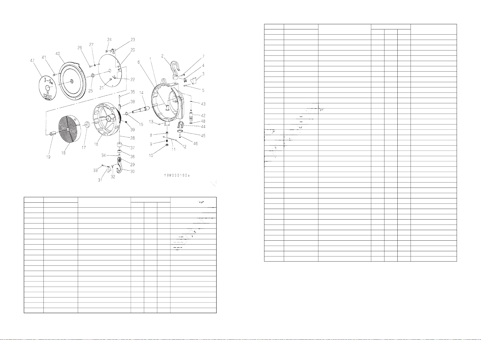
11.部品一覧表/PARTSLISTELF−3,ELF−5,ELF−9照合番号Ref. No. 部品番号Part No. 部品名称個数/Quantity
ELF−3 ELF−5 ELF−9
Description
111111111111111211111111111111111112111111111111111111121111Casing assembly
-
Casing
-
Hook complete
--
Hook
--
Latch set
---
Latch
---
Spring
---
Rivet
--
Shaft
--
Rivet
Drum lock assembly
-
Pin
-
Spring
-
Collar
-
Spring pin
Cap
Set screw
Spindle
O-ring
Drum
ケース部1式−ケース−フック1式−−フック−−外レ止メ1式−−−外レ止メ−−−スプリング−−−丸リベット−−シャフト−−丸リベットドラムロック部1式−ピン−スプリング−カラー−スプリングピンキャップ六角穴付止ネジスピンドルOリングドラムLBP001317
P2B100141
LBP000262
LBP000263
LBP001318
P2B400348
P2B400041
P2B300957
P2B401573
P2B100140
-
-
-
-
-
-
-
-
-
-
−1−2−34567−8910111213141516
-
21
-
-
-
-
-
-
-
-
-
-
-
-
-
-
-
-
照合番号Ref. No. 部品番号Part No. 部品名称個数/QuantityDescription
11−−1111111133111111111111111131111121−−1−1−111111113311111111111111113111112−1−1−−1111111113311111111111111113111111112−−1Ball bearing
Spring
Spring
Spring
Bushing
Disc assembly
-
Cover
-
Rivet
-
Spring
-
Stopper
-
Rivet
Bushing
Screw
Spring washer
Wire rope assembly
-
Wire rope
-
Thimble
-
Hook complete
--
Hook
--
Latch set
---
Latch
---
Spring
---
Rivet
-
Lock tube
-
Lock tube
-
Collar
-
Buffer
Bushing
Screw
Cover
Screw
Worm
Retaining ring
Wire guide set
-
Wire guide
-
Wire guide
-
Hex.socket button bolt
Name plate
Name plate
Name plate
O-ring
ボールベアリングスプリングスプリングスプリングブッシュディスク1式−カバー−リベット−スプリング−ストッパ−リベットブッシュ十字穴付ナベ小ネジバネ座金ワイヤロープ1式−ワイヤロープ−シンブル−フック1式−−フック−−外レ止メ1式−−−外レ止メ−−−スプリング−−−丸リベット−ロック管−ロック管−カラー−緩衝ゴムブッシュ
座金組込ミ六角穴付ボルト
カバー
座金組込ミ十字穴付ナベ小ネジ
ウォームE形止メ輪ワイヤガイド1式−ワイヤガイド−ワイヤガイド−六角穴付ボタンボルトネームプレートネームプレートネームプレートOリングKA60104010
P2B300950
P2B300951
P2B300952
P2B401584
LBP001299
P2B401579
KA10120512
KA31120500
LBP001300
LBP001505
LBP001524
P2B400149
P2B400146
P2B401575
P2B401619
P2B200190
P2B400860
P2B300446
KA40310050
LBP001021
P2B401213
P2B300954
P2B300955
P2B300956
KA50200140
1718181819−2021222324252627−2829−30−31323334353637383940414243−44454647474748ご注意)ご注文の際には、部品番号、部品名称および製品の型式を指定してください。尚、部品番号のない部品は個々に供給できません。セット又は1式でご購入ください。NOTE)Whenplacinganorder,clearlyspecitytheproductmodel,partnumberanddescription.Partswithoutapartnumbercannotbesuppliedindividually.Pleasepurchaseasetorcompleteunit.
ELF−3 ELF−5 ELF−9
-
22
-
Copied
Copied
Description
Description
digital
data
data
data
data
30
30
from
from
from
Hook
Latch set
Latch set
---
LatchLatch
------
SpringSpring
------
http://www.endo-kogyo.co.jp/
http://www.endo-kogyo.co.jp/
http://www.endo-kogyo.co.jp/
http://www.endo-kogyo.co.jp/
Casing assembly
Hook complete
Hook complete
http://www.endo-kogyo.co.jp/
http://www.endo-kogyo.co.jp/
http://www.endo-kogyo.co.jp/
http://www.endo-kogyo.co.jp/
-
http://www.endo-kogyo.co.jp/
http://www.endo-kogyo.co.jp/
-
--
http://www.endo-kogyo.co.jp/
http://www.endo-kogyo.co.jp/
http://www.endo-kogyo.co.jp/
http://www.endo-kogyo.co.jp/
http://www.endo-kogyo.co.jp/
http://www.endo-kogyo.co.jp/
http://www.endo-kogyo.co.jp/
バネ座金
バネ座金
ワイヤロープ1式
ワイヤロープ1式
0120512
11205001120500
LBP001300LBP001300
LBP001505LBP001505
LBP001524LBP001524
3131
3232
3333
34
34
2019年6月 2000部N本社営業部新潟県燕市秋葉町3丁目14番7号〒
959
−
1261
電話(0256)62−5133番(代表) FAX(0256)62−5772番東京営業部東京都千代田区神田東松下町12-2JBSL神田ビル2F〒
101
−
0042
電話(03)5295−3711番(代表) FAX(03)5295−3717番大阪営業部大阪市浪速区幸町2丁目3番14号 ダイトービル3F〒
556
−
0021
電話(06)6568−1571番(代表) FAX(06)6568−1573番
名古屋営業所
名古屋市中区大須1丁目7番14号 パークIMビル3F〒
460
−
0011
電話(052)253−6231番(代表) FAX(052)253−6240番九州営業所
福岡市博多区博多駅東3丁目11番15号 文喜ビル3F
〒
812
−
0013
電話(092)412−5281番(代表) FAX(092)412−5280番URLhttp://www.endo-kogyo.co.jpURLhttp://www.endo-kogyo.co.jpIf be!P g g jdf;! 4.25.8-!Bljc b.dip-U tvcbnf- !Ojjhbu b-!Kbqb o
! Ufm/! 1 3 6 7
‒
7 3
‒
6 2 4 4 ! Gby/!1 3 6 7
‒
7 3
‒
6 8 8 3
Uplzp!Pggjdf;! KCTM!Lbo eb!Cmeh /-!3G-! 23.3-!
! Lboeb !Ijhbti j!Nbutvtijub.dip-!Dijzpeb.lv-
! Uplzp -!Kbqbo
! Ufm/! 1 4
‒
6 3 : 6
‒
4 8 2 2 ! Gby/!1 4
‒
6 3 : 6
‒
4 8 2 8
Ptblb!Pggjdf;! Ebjup!Cmeh/-!4G-!4 .25-!Tb jxbj.di p!3.dip nf-
! Obojx b.lv-!P tblb-!Kbqbo
! Ufm/! 1 7
‒
7 6 7 9
‒
2 6 8 2 ! Gby/!1 7
‒
7 6 7 9
‒
2 6 8 4
Obhpzb!Pggjdf;! Qbsl !JN!Cme h/-!4G-!2.8.25-!Ptv-
! Oblb. lv-!Obh pzb-!Bjdij-Kbqbo
! Ufm/! 1 6 3
‒
364
‒
7 3 4 2 ! Gby/!1 6 3
‒
3 6 4
‒
7 3 5 1
Lzvtiv!Pggjdf;! Cvolj!Cmeh/-!4G-22.26-!Iblbubfljijhbtij!4.dipnf-
! Iblbu b.lv-!G vlvplb-!Kbqbo
! Ufm/! 1 : 3
‒
523
‒
6 3 9 2 ! Gby/!1 : 3
‒
5 2 3
‒
6 3 9 1
Copied
1261
1261
東京都千代田区神田東松下町
東京都千代田区神田東松下町
101101
−
−
00420042
電話(
電話(
大阪営業部
大阪営業部
大阪市浪速区幸町2丁目3番14号 ダイトービル3大阪市浪速区幸町2丁目3番14号 ダイトービル3
〒
〒
556556
名古屋市中区大須1丁目7番14号 パークIMビル3
名古屋市中区大須1丁目7番14号 パークIMビル3
digital
digital
digital
digital
digital
digital
新潟県燕市秋葉町3丁目14番7
新潟県燕市秋葉町3丁目14番7
電話(
電話(
FA
FA
X(
X(
data
data
from
from
from
http://www.endo-kogyo.co.jp/
http://www.endo-kogyo.co.jp/
http://www.endo-kogyo.co.jp/
http://www.endo-kogyo.co.jp/
http://www.endo-kogyo.co.jp/
新潟県燕市秋葉町3丁目14番7新潟県燕市秋葉町3丁目14番7
025025
6
6
)
)
62−
62−
X(
X(
025
025
66
)
)
東京都千代田区神田東松下町東京都千代田区神田東松下町
電話( 電話(
0303
)
)
FA
FA
X(X(
03
03
大阪市浪速区幸町2丁目3番14号 ダイトービル3大阪市浪速区幸町2丁目3番14号 ダイトービル3
00210021
電話( 電話(
http://www.endo-kogyo.co.jp/
FA
FA
名古屋市中区大須1丁目7番14号 パークIMビル3名古屋市中区大須1丁目7番14号 パークIMビル3
〒〒
460
460
−
−
00110011
所
所
福岡市博多区博多駅東3丁目11番15号 文喜ビル3F福岡市博多区博多駅東3丁目11番15号 文喜ビル3F
〒〒
812
812
http://www.endo-kogyo.co.jp/
Other manuals for ELF-3
1
This manual suits for next models
2
Table of contents
Other Endo Safety Equipment manuals


