ENGWE YL81C User manual

User Msnual for
E-bike Display
YL81C

Table of Contents
1. Function overview and functional area layout ....................................................................................................................1
1.1 Function overview ..................................................................................................................................................... 1
1.2 Functional area layout .............................................................................................................................................. 1
1.3 Button definitions ...................................................................................................................................................... 1
2. General operation ..................................................................................................................................................................1
2.1 Power on/off ............................................................................................................................................................... 1
2.2 Display interface ........................................................................................................................................................1
2.3 Push assistance ...........................................................................................................................................................2
2.4 Assist level selection ...................................................................................................................................................2
2.5 Battery level indicator ...............................................................................................................................................3
2.6 Error code indicator ..................................................................................................................................................3
3. General setting ........................................................................................................................................................................3
3.1 Trip distance reset ..................................................................................................................................................... 3
3.2 Factory reset .............................................................................................................................................................. 3
4. Custom setting ........................................................................................................................................................................ 4
4.1 Rated voltage setting ................................................................................................................................................. 4
4.2 Wheel diameter setting ............................................................................................................................................. 4
4.3 Speed limit setting ..................................................................................................................................................... 5
4.4 Metric/imperial system setting .................................................................................................................................5
4.5 Speed sensor setting .................................................................................................................................................. 5
4.6 Current limit setting ..................................................................................................................................................6
4.7 Assistance sensor setting ........................................................................................................................................... 6
4.8 Power-on password setting .......................................................................................................................................6
5. Considerations ........................................................................................................................................................................ 7
1
1. Function overview and functional area layout
1.1 Function overview
Display M20 provides a variety of functions to meet the riding needs of users, including:
● Battery level indicator
● Assist level adjustment and indication
● Headlight indicator
● Speed indicator (including real-time speed, maximum speed (MAXS) and average speed (AVG))
● Distance indicator (including ODO and trip distance (Trip))
● Error code indicator
● Bluetooth connection indicator (reserved)
● Parameter setting function
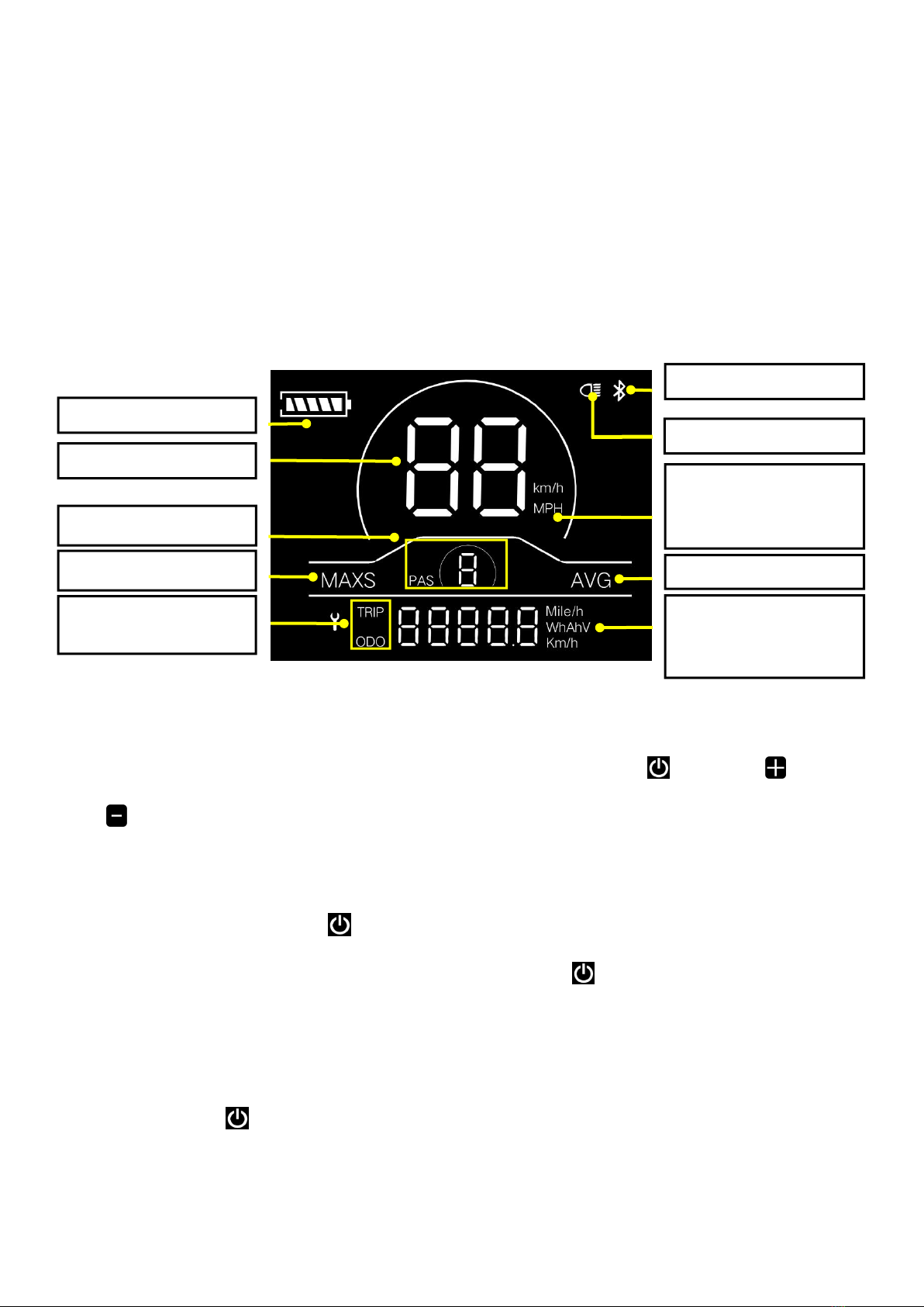
1.2 Functional area layout
Fig. 1-1 Functional Area Layout Interface of Display M20
1.3 Button definitions
There are three buttons on the operating unit of display M20,i.e., the on/off button , plus button and minus
button .
2. General operation
2.1 Power on/off
By pressing and holding the button , the display will start to work and the working power supply of the controller
will be turned on. In the power-on state, by pressing and holding the button , your e-bike will be powered off. In the
power-off state, the display will no longer use the battery power, and its leakage current will be less than 1uA.
■ If your e-bike is not used for more than 10 minutes, the display will be automatically powered off.
2.2 Display interface
After the display is turned on, the display will show the real-time speed (km/h) and the trip distance (km) by default.
By pressing the button , the information displayed will be switched between the trip distance (km),ODO (km),
maximum speed (km) and average speed (km).
When the distance reaches 9999.9 km, it will be automatically reset to zero.
Maximum speed
indicator
Average speed indicator
Battery level indicator
Bluetooth indicator
Speed indicator
Speed unit
Metric system: km/h
Imperial system: MPH
Headlight indicator
Assist level indicator
Distance/speed unit
Metric system: km, km/h
Imperial system: mile,
Trip distance indicator
ODO

2
Trip distance indicator
ODO
Average speed indicator
Maximum speed indicator
Fig. 2-1 Display Interface Switching
2.3 Push assistance
By pressing and holding the button , the electric push assistance mode will be enabled. Your e-bike will run at the
constant speed of 6km/h. The display will show level P. By releasing the button , your e-bike will immediately stop
power output and return to the state before push assistance.
Fig. 2-2 Push Assistance Indicator Interface
2.4 Assist level selection
By pressing the button / , the e-bike assist level will be switched to change the motor output power. The assist
levels available for the display include: levels 0-3, levels 1-3, levels 0-5, levels 1-5, levels 0-7, levels 1-7, levels 0-9 and
levels 1-9.
Fig. 2-3Assist Level Switching Interface

3
2.5 Battery level indicator
The battery level indicator consists of five segments. When the battery is fully charged, the five segments will be all on.
In case of undervoltage, the outline of the battery indicator will flash, which means the battery has to be charged
immediately.
Full battery level
indication
4-segment
indication
3-segment
indication
2-segment
indication
1-segment
indication
Undervoltage
flashing
Fig. 2-4 Battery Level Indicator Interface
2.6 Error code indicator
When a fault occurs in the electronic control system of your e-bike, the display will automatically indicate the error
code in the distance area in the format of E0**. Detailed definitions of error codes are shown in Schedule 1.
Fig. 2-5 Error Code Indicator Interface
■ When an error code appears on the display interface, please conduct troubleshooting in time. Otherwise, your
e-bike will not work normally.
3. General setting
■ All parameters can only be set when your e-bike stops.
The steps for general setting are as follows:
In the power-on state, when the display shows the speed of 0,
3.1 Trip distance reset
Press and hold the buttons and at the same time for more than 2 seconds to reset the trip distance.
3.2 Factory reset
dEF refers to factory reset. dEF-n represents not to restore factory settings, and dEF-y represents to restore factory
settings. Press and hold the buttons and at the same time for more than 2 seconds to enter the factory reset
interface, and press the button / to select a parameter.
Fig. 3-1 Factory Reset Interface
4
4. Custom setting
■ All parameters can only be set when your e-bike stops.
The steps for custom setting are as follows:
In the power-on state, when the display shows the speed of 0,
(1) Press and hold the buttons and at the same time for more than 2 seconds to enter the selection interface of
custom setting options;
(2) Press the button / to switch the selection interface of general setting options, and press the button to
enter the parameter modification interface;
(3) Press the button / for parameter selection;
(4) Press the button to save the parameter and return to the selection interface of custom setting options;
(5) Press and hold the button to save the parameter and exit the selection interface of custom setting options.
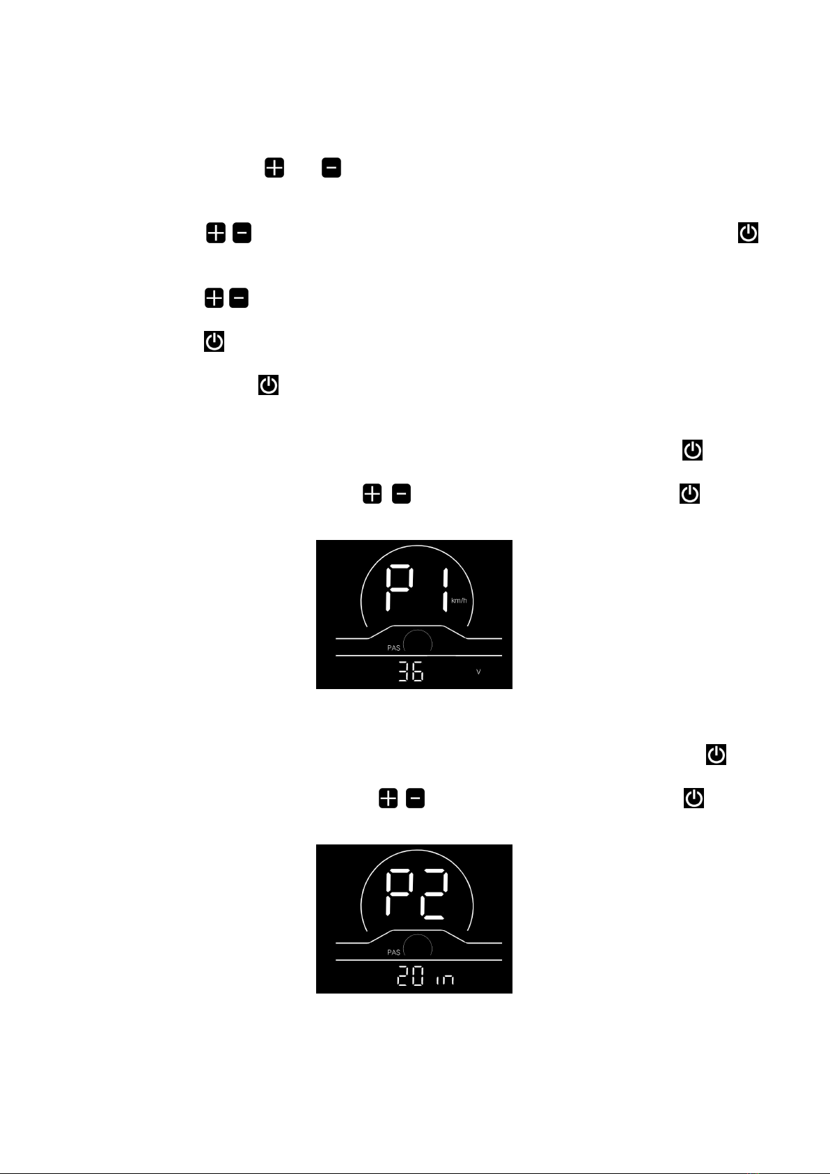
4.1 Rated voltage setting
P1 refers to the rated voltage setting option. Available values include: 36V and 48V. Press the button to enter the
parameter modification interface. Press the button / for parameter selection. Press the button to save the
parameter and return to the selection interface of general setting options.
Fig. 4-1 Rated Voltage Setting Interface
4.2 Wheel diameter setting
P2 refers to the wheel diameter setting option. Available parameters include: 8-32 inches. Press the button to enter
the parameter modification interface. Press the button / for parameter selection. Press the button to save the
parameter and return to the selection interface of general setting option.
Fig. 4-2 Wheel Diameter Setting Interface

5
4.3 Speed limit setting
P3 represents the speed limit setting option. The adjustable range is 10~60km/h. Press the button to enter the
parameter modification interface. Press the button / for parameter selection. Press the button to save the
parameter and return to the selection interface of general setting options.
Fig. 4-3 Speed Limit Setting Interface
4.4 Metric/imperial system setting
P4 refers to the metric/imperial system setting option. 00 represents the metric system, and 01 represents the imperial
system. Press the button to enter the parameter modification interface. Press the button / for parameter
selection. Press the button to save the parameter and return to the selection interface of general setting options.
Metric system indicator interface
Imperial system indicator interface
Fig. 4-4 Metric/imperial System Setting Interface
4.5 Speed sensor setting
P5 refers to the speed sensor setting option, which can be set according to the number of magnetic heads installed on
the wheels of your e-bike. The setting range is 1-63. Press the button to enter the parameter modification interface.
Press the button / for parameter selection. Press the button to save the parameter and return to the selection
interface of general setting options.
Fig. 4-5 Speed Sensor Setting Interface

6
4.6 Current limit setting
P6 refers to current limit setting. The adjustable range is 1-25A. Press the button to enter the parameter
modification interface. Press the button / for parameter selection. Press the button to save the parameter and
return to the selection interface of general setting options.
Fig. 4-6 Current Limit Setting Interface
4.7 Assistance sensor setting
P7 refers to the assistance sensor setting option, where the number of steel magnets of the assistance magnetic disk can
be set. The adjustable range is 5, 6, 7, 8, 9, 10 and 12. Press the button to enter the parameter modification interface.
Press the button / for paramter selection. Press the button to save the parameter and return to the selection
interface of general setting options.
Fig. 4-7 Assistance Sensor Setting Interface
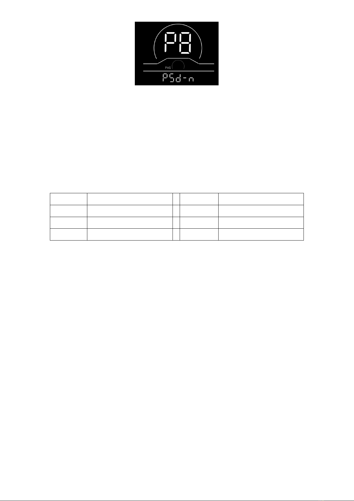
4.8 Power-on password setting
P8 refers to the power-on password setting option. PSd-Y means that a power-on password is required, and PSd-N
means that no power-on passwords are required. The default value of the display is PSd-N. Press the button to enter
the modification interface, and press the button / to enter the selection interface.
If PSd-N is selected, press the button to return to the selection interface of custom setting options;
If PSd-Y is selected, press the button to enter the password setting interface. If you don’t want to change the
password, press and hold the button to exit the custom setting interface. If you want to change the password, press the
button for cursor movement and the button / for figure selection, and then press the button to return to
the selection interface of custom setting options.
7
Fig. 4-8 Power-on Password Setting Interface
5. Considerations
Please use safely, and do not plug or unplug the display when it is powered on.
◆Please avoid bumping as far as possible.
◆Please do not alter the background parameter settings of the display at will, otherwise normal riding cannot be
guaranteed.
◆If the display fails to work normally, it should be repaired as soon as possible.
◆Due to product upgrades of the Company, part of the displayed contents or functions of product you bought may be
different form the manual, depending on the actual model.
Schedule 1 Error Code Definitions
Error codes
for
Definition
Error codes
for protocols
Definition
E021
Current Abnormality
E024
Motor Hall Signal Abnormality
E022
Throttle Abnormality
E025
Brake Abnormality
E023
Motor Phase Abnormality
E030
Communication Abnormality
Table of contents
Other ENGWE Bicycle Accessories manuals


