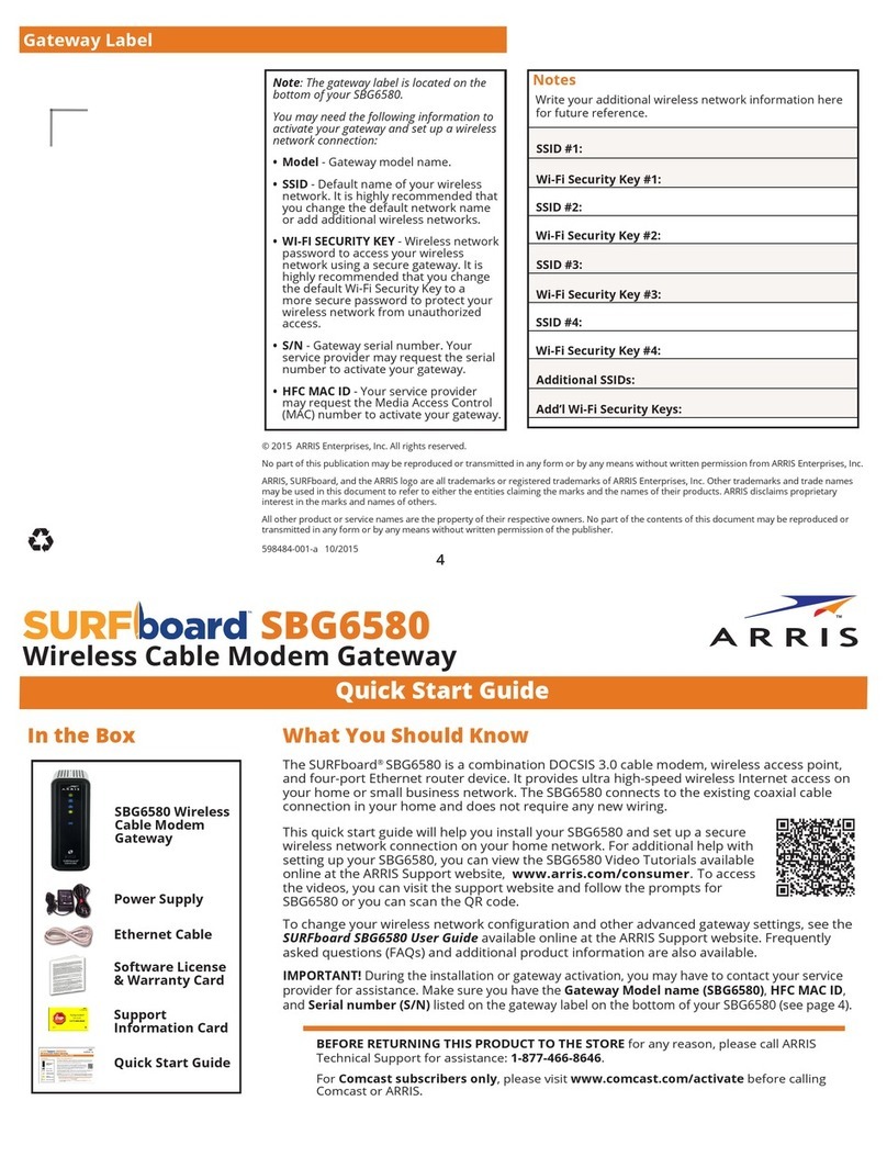
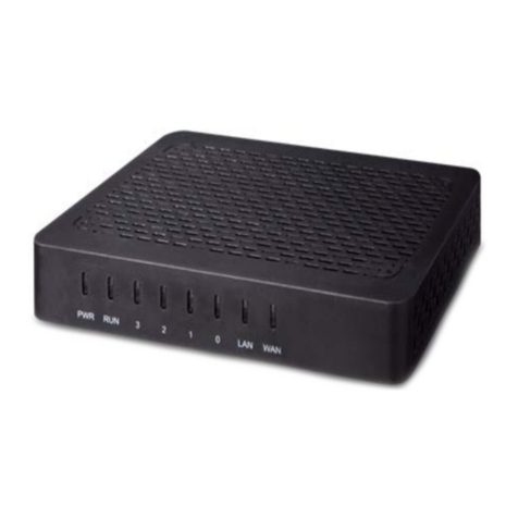
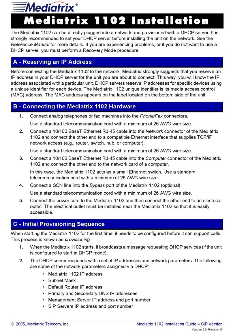
Environdata MB40 User manual

MB40 & MB45 MODBUS
TCP/IP Gateway
Handbook
Version 1.2
29 July 2014
Environdata Australia Pty Ltd
42-44 Percy Street Warwick
Queensland 4370 Australia
Phone: (07) 4661 4699
Fax: (07) 4661 2485
International Phone: +61 7 4661 4699
International Fax: +61 7 4661 2485
http://www.environdata.com.au
Material in this handbook is Copyright.
All rights reserved by the publishers.
No reproduction without the prior permission of the publishers.

MB40 & MB45 MODBUS TCP/IP Gateway Page 1of 21
MB40 & MB45 MODBUS TCP/IP Gateway –DL30 type Environdata
Weather Stations
Connects an Environdata DL3000 Weather Station to a Modbus network
Modbus RTU over RS485 and Modbus TCP/IP over Ethernet compatible
Easy Modbus TCP/IP configuration via webpage, Modbus registers, or on-board switches
Supports three simultaneous Modbus TCP masters.
Retrieves current weather values, 10 minute values, hourly values, and daily values.
Can be used to synchronise the date and time of the Weather Station directly
Overview
The MB40 Modbus TCP DL3000 Gateway allows the easy connection of a PLC (Programmable Logic
Controller), RTU (Remote Telemetry Unit) or SCADA System to a Weather Station. Using the Modbus
RTU (Binary), or Modbus TCP/IP (Ethernet) protocols, it enables a programmable controller to
monitor and carry out actions based on wind speed, wind direction, temperature and many other
weather based variables.
The MB40 Modbus TCP DL3000 Gateway is a major upgrade to MB30 Serial DL3000 Gateway. It
provides all the functionality of the MB30, with the following improvements:
Addition of Ethernet:
Allows the MB40 to be polled by up to three Modbus TCP/IP masters simultaneously
Provides a webpage whereby TCP/IP settings can be easily monitored and altered. Also
shows current communications statuses.
Can be interrogated over HTTP to return Modbus register values in XML format
Retrieves the current weather data, as well as the 10 minute, hourly, and daily weather data.
Allows up to 125 registers to be polled at once –previously limited to 30.
Provides a method to set up the date and time of the DL3000 Weather Station.
Turns off “verbose mode” on the weather station.
MB40 is a standalone version that is suitable for DIN rail mounting, while MB45 is enclosed in the
sealed housing of the weather recorder with access via a sealed gland.

MB40 & MB45 MODBUS TCP/IP Gateway Page 2of 21
Please Note
Please note that Environdata’s software program, EasiAccess, will NOT connect to the MB40 / MB45.
This is because EasiAccess does NOT use the MODBUS protocol.
EasiAccess can connect DIRECTLY to an Environdata Weather Station via either a LAN (TCP/IP)
address or a serial (COM) port. But in both cases, the communication is text commands, and NOT
MODBUS commands.
MODBUSVIEW TCP is a program that can connect via either a LAN (TCP/IP) address or a serial (COM)
port, and does use MODBUS commands. You can get a copy of this program either from the
Environdata EasiAccess distribution CD or download from the Internet at
https://oceancontrols.com.au/OCS-011.html
As a free copy, MODBUSVIEW TCP will work for 15 minutes as a test program. Restarting the
program will provide a further 15 minutes operation, as required.

MB40 & MB45 MODBUS TCP/IP Gateway Page 3of 21
Contents
MB40 & MB45 MODBUS TCP/IP Gateway –DL30 type Environdata Weather Stations ........................ 1
Overview .............................................................................................................................................1
Please Note .........................................................................................................................................2
Getting Started.................................................................................................................................... 4
Configuring the MB40..................................................................................................................... 4
Configuring Modbus ...........................................................................................................................5
Modbus RTU....................................................................................................................................5
Modbus TCP/IP & Ethernet Webserver .............................................................................................. 6
Configuration Using Switches –Switch 1......................................................................................... 6
Configuration Using Switches –Switch 2......................................................................................... 6
Configuration Using Switches –Switch 3 & 4 .................................................................................. 7
Configuration Using Switches –Switch 5 to 8 .................................................................................7
Configuration Using Webpage ........................................................................................................7
Configuration Using Modbus (RTU or TCP/IP) ................................................................................ 8
Weather Station Data ......................................................................................................................... 9
Current Weather Data ....................................................................................................................9
Daily Weather Data.........................................................................................................................9
Last Hourly Data.............................................................................................................................. 9
Last 10-Minute Data......................................................................................................................10
Functionality .....................................................................................................................................10
Weather Station Polling Period..................................................................................................... 10
Weather Station Date and Time Configuration ............................................................................ 11
Webpage...........................................................................................................................................12
XML Request .....................................................................................................................................13
Single Register............................................................................................................................... 13
All Registers...................................................................................................................................14
Error Request ................................................................................................................................15
Troubleshooting................................................................................................................................16
Power Connected..........................................................................................................................16
Weather station Comms ...............................................................................................................16
Ethernet ........................................................................................................................................16
RS485 ............................................................................................................................................16
Troubleshooting Procedure ..........................................................................................................16
Appendix A........................................................................................................................................19
Complete Holding Register Listing ................................................................................................ 19

MB40 & MB45 MODBUS TCP/IP Gateway Page 4of 21
Getting Started
Configuring the MB40
Table 1: Connections to the MB40
Connection
Description
V +
Power Positive (8 to 28V DC)
GND
Power Negative (Ground)
D +
RS485 Data +
D -
RS485 Data -
GND
Ground
Male D9
Serial communications (RS232) between MB40 and Weather Station
RJ45 Socket
Ethernet Port
Table 2: MB40 LED Functions
LED
Function
Red Tx LED (next to RS485 terminal)
Indicates serial communications received on RS485
Green Rx LED (next to RS485
terminal)
Indicates serial communications sent (Modbus RTU) on
RS485
Green Rx LED next to D9 connector
Indicates serial communications received (from weather
station) on the serial port
Red Tx LED next to D9 connector
Indicates serial communications sent on the serial port
Green LED (right side) on RJ45 socket
Link LED. Always on to indicate good status for Ethernet,
flashes to indicate activity.
Yellow LED (left side) on RJ45 socket
FDX LED.
On = Full duplex Ethernet
Off = Half duplex Ethernet
Green Rx LED next to RJ45 socket
Flashes when packets are received on the Ethernet port.
Red Tx LED next to RJ45 socket
Flashes when packets are sent on the Ethernet port.

MB40 & MB45 MODBUS TCP/IP Gateway Page 5of 21
Configuring Modbus
Modbus RTU
Serial Modbus is provided on RS485. The communications settings for this port are set 8 DIP
switches next to the D9 connector. Any changes to the switches won’t take effect until the MB40 is
power cycled.
Table 3: Modbus RTU address switches
Modbus RTU Address
Switch 1
Switch 2
Switch 3
Switch 4
1
OFF
OFF
OFF
OFF
2
ON
OFF
OFF
OFF
3
OFF
ON
OFF
OFF
4
ON
ON
OFF
OFF
5
OFF
OFF
ON
OFF
6
ON
OFF
ON
OFF
7
OFF
ON
ON
OFF
8
ON
ON
ON
OFF
9
OFF
OFF
OFF
ON
10
ON
OFF
OFF
ON
11
OFF
ON
OFF
ON
12
ON
ON
OFF
ON
13
OFF
OFF
ON
ON
14
ON
OFF
ON
ON
15
OFF
ON
ON
ON
16
ON
ON
ON
ON
Table 4: Modbus RTU Baud Rate switches
Baud Rate
Switch 5
Switch 6
2400
OFF
OFF
4800
ON
OFF
9600
OFF
ON
19200
ON
ON
Table 5: Modbus RTU Parity switches
Parity
Switch 7
Switch 8
None
OFF
OFF
Even
ON
OFF
Odd
OFF
ON
Boot-loader1
ON
ON
1
The boot-loader is an advanced function that allows firmware updates to be deployed in the field.

MB40 & MB45 MODBUS TCP/IP Gateway Page 6of 21
Modbus TCP/IP & Ethernet Webserver
To communicate over a TCP/IP network, the MB40 needs five pieces of information:
1. The Internet Protocol (IP) address of the MB40 within the network. Set by the user
2. The Subnet Mask of the network. Set by the user
3. The Default Gateway of the network. Set by the user.
4. A unique MAC address. Shipped preloaded by Environdata.
5. The TCP/IP port the request is being sent on. For the MB40, Modbus TCP/IP is on port 502,
and the webserver (HTTP) is on port 80.
These settings themselves can be set by one of three available methods:
1. The 8 DIP switches next to the D9 connector.
2. Modbus registers (using either Modbus RTU on RS485 or Modbus TCP/IP on Ethernet)
3. The webpage.
Configuration Using Switches –Switch 1
Switch one determines where the TCP/IP settings are loaded from when power is applied to the
MB40. With this switch off, settings are loaded from the current values of the switches, regardless of
previous settings. With the switch on, the settings are loaded from internal memory - saved after
being previously configured via the webpage or Modbus.
Table 6: TCP/IP mode switch
Power Up Configuration
Switch 1
OFF
TCP/IP settings from switches
ON
TCP/IP settings from internal persistent memory
Configuration Using Switches –Switch 2
Switch two is the “panic switch”, returning the MB40 to default if the user writes incorrect values or
doesn’t otherwise know what settings the card currently possesses. To use, flick the switch on, hold
for one second, and turn back off again. Don’t leave this switch on; the card will be constantly
resetting and therefore unresponsive.
Default Values
IP Address: 192.168.1.100
Subnet Mask: 255.255.255.0
Default Gateway: 192.168.1.1
Table 7: TCP/IP Reset Switch
Reset to Default
Switch 2
OFF
No action
ON
TCP/IP settings reset to default

MB40 & MB45 MODBUS TCP/IP Gateway Page 7of 21
Configuration Using Switches –Switch 3 & 4
Switches three and four choose between four different TCP/IP schemes commonly used in private
address space:
Table 8: TCP/IP Subnet switches
TCP/IP Base Settings
Switch 3
Switch 4
IP Address: 192.168.1.x
Subnet Mask: 255.255.255.0
Default Gateway: 192.168.1.1
OFF
OFF
IP Address: 10.0.0.x
Subnet Mask: 255.0.0.0
Default Gateway: 10.0.0.1
OFF
ON
IP Address: 10.1.1.x
Subnet Mask: 255.255.0.0
Default Gateway: 10.1.1.1
ON
OFF
IP Address: 172.16.0.x
Subnet Mask: 255.240.0.0
Default Gateway: 172.16.0.1
ON
ON
Configuration Using Switches –Switch 5 to 8
The final four switches determine the last octet of the IP address.
Table 9: TCP/IP IP Address switches
Last Octet (IP Address)
Switch 5
Switch 6
Switch 7
Switch 8
100
OFF
OFF
OFF
OFF
101
ON
OFF
OFF
OFF
102
OFF
ON
OFF
OFF
103
ON
ON
OFF
OFF
104
OFF
OFF
ON
OFF
105
ON
OFF
ON
OFF
106
OFF
ON
ON
OFF
107
ON
ON
ON
OFF
108
OFF
OFF
OFF
ON
109
ON
OFF
OFF
ON
110
OFF
ON
OFF
ON
111
ON
ON
OFF
ON
112
OFF
OFF
ON
ON
113
ON
OFF
ON
ON
114
OFF
ON
ON
ON
115
ON
ON
ON
ON
Configuration Using Webpage
The MB40 has an inbuilt web server that can service HTTP requests on port 80. Simply point your
web browser to the IP Address of the MB40 to retrieve this page.

MB40 & MB45 MODBUS TCP/IP Gateway Page 8of 21
Below the current communications statuses is a web form with provision to set the TCP/IP settings
of the MB40. The form fields will be populated with the Gateway’s current values. These can be
altered and written to the MB40.
After writing these values, you will likely want to change TCP switch 1 to read from memory on the
next power up, otherwise the TCP/IP configuration will read from the switches.
Configuration Using Modbus (RTU or TCP/IP)
The MB40 has 13 Modbus holding registers reserved for configuration. These settings can be read
and written using either serial Modbus (RTU on RS485) or Modbus TCP/IP.
Table 10: Modbus TCP/IP Configuration Registers
Modbus Register
Function
256
1st octet IP Address
257
2nd octet IP Address
258
3rd octet IP Address
259
4th octet IP Address
260
1st octet Subnet Mask
261
2nd octet Subnet Mask
262
3rd octet Subnet Mask
263
4th octet Subnet Mask
264
1st octet Default Gateway
265
2nd octet Default Gateway
266
3rd octet Default Gateway
267
4th octet Default Gateway
268
Commit to Gateway (write a 1)
Each register holds one octet of the TCP/IP configuration. These can be read to view the current
TCP/IP settings, or written to set the values. Once all twelve octets are manually set, the settings are
committed to the gateway by writing a one to holding register 268. Make sure all registers are
written with correct values before they are committed to the gateway.

MB40 & MB45 MODBUS TCP/IP Gateway Page 9of 21
Weather Station Data
The gateway operates as a Modbus slave. To access the holding registers in the gateway, the PLC or
RTU must be configured as a Modbus Master. Using Modbus Function 3, the PLC can read the
Holding Registers.
Current Weather Data
Table 11: R3 Modbus Register Listing
Holding Register
Address 40,000+
No. of
Registers
Type
Description
1
1
Time
Year in format YYYY
2
1
Time
Month and day in format MMDD
3
1
Time
Hour in format HH
4
1
Time
Minute and second in format MMSS
5 to 59
1
Data
Unpacked weather data. Up to 54 “pieces” of comma separated
data is sequentially unpacked and placed into holding registers.
60
1
Status
Comms status for the R3 command. 0 = bad, 1 = good.
Daily Weather Data
Table 12: MEM 1 LAST Modbus Register Listing
Holding Register
Address 40,000+
No. of
Registers
Type
Description
61
1
Time
Year in format YYYY
62
1
Time
Month and day in format MMDD
63
1
Time
Hour in format HH
64
1
Time
Minute and second in format MMSS
65 to 119
1
Data
Unpacked weather data. Up to 54 “pieces” of comma separated
data is sequentially unpacked and placed into holding registers.
120
1
Status
Comms status for the MEM 1 LAST command. 0 = bad, 1 = good.
Last Hourly Data
Table 13: MEM 2 LAST Modbus Register Listing
Holding Register
Address 40,000+
No. of
Registers
Type
Description
121
1
Time
Year in format YYYY
122
1
Time
Month and day in format MMDD
123
1
Time
Hour in format HH
124
1
Time
Minute and second in format MMSS
125 to 179
1
Data
Unpacked weather data. Up to 54 “pieces” of comma separated
data is sequentially unpacked and placed into holding registers.
180
1
Status
Comms status for the MEM 2 LAST command. 0 = bad, 1 = good.

MB40 & MB45 MODBUS TCP/IP Gateway Page 10 of 21
Last 10-Minute Data
Table 14: MEM 3 LAST Modbus Register Listing
Holding Register
Address 40,000+
No. of
Registers
Type
Description
181
1
Time
Year in format YYYY
182
1
Time
Month and day in format MMDD
183
1
Time
Hour in format HH
184
1
Time
Minute and second in format MMSS
185 to 239
1
Data
Unpacked weather data. Up to 54 “pieces” of comma separated
data is sequentially unpacked and placed into holding registers.
240
1
Status
Comms status for the MEM 3 LAST command. 0 = bad, 1 = good.
Weather Station Data Notes:
1. The gateway decodes comma separated values. Once the date code has been deciphered,
the remaining data is chopped into individual numbers, treating the comma as a separator.
Each number is converted and packed into the next available holding register, up to a limit of
54 numbers.
2. Weather Station data is internally limited to ±32760. Values beyond this range are capped to
an error code shown below.
3. The decimal point is ignored in all cases. This could cause overflow on semantically in range
numbers such as 12345.67, and also 10000.00.
4. Numbers larger than 32760 are displayed as the error value: 32761
5. Numbers smaller than -32760 are displayed as the error value: 32762
6. Weather station +OVERFLOW values are displayed as error code: 32763
7. Any other conversion failure is displayed as: 32764
8. No arithmetic is done using floating point numbers. There is therefore no underflow error.
Functionality
Weather Station Polling Period
By default, the gateway asks for each data packet from the weather station every 2.5 seconds. The
polling period can be changed by writing to Modbus register 247. Enter your preferred polling period
as a number in tenths of seconds (i.e for 2.5 seconds enter 25).

MB40 & MB45 MODBUS TCP/IP Gateway Page 11 of 21
Weather Station Date and Time Configuration
The date and time of the weather station can be directly altered by the MB40, by writing to specific
Modbus Registers. The date command is of the following format:
SET DATE YYYY MM DD<cr>
Where each argument is set using the Modbus registers:
SET DATE holding_register[248] holding_register[249] holding_register[250] <cr>
The command is sent to the Weather Station by writing a 1 to Holding Register 251.
Similarly, the time command is of the following format:
SET TIME HH MM SS<cr>
Where each argument is set using the Modbus registers:
SET TIME holding_register[252] holding_register[253] holding_register[254] <cr>
The command is sent to the Weather Station by writing a 1 to Holding Register 255.
Note that there is no error checking on this interface. Once a one is written to the send register, the
command will be sent to the weather station, even if there is garbage or incorrect arguments
specified. Take care when using this functionality.
Table 15: EEPROM Write Modbus Register Listing
Modbus Holding
Register
Description
248
Year argument
Four digits: format YYYY
249
Month argument
Two digits: format MM. Padded with leading
zeroes.
250
Day argument
Two digits: format DD. Padded with leading
zeroes.
251
Commit Date to Weather Station
Write a 1 to send date command.
252
Hour argument
Two digits: format HH. Padded with leading
zeroes.
253
Minute argument
Two digits: format MM. Padded with leading
zeroes.
254
Second argument
Two digits: format SS. Padded with leading
zeroes.
255
Commit Time to Weather Station
Write a 1 to send time command.

MB40 & MB45 MODBUS TCP/IP Gateway Page 12 of 21
Webpage
In addition to providing an interface to read and write the TCP/IP configuration values, the webpage
also provides the user with a view of the current status of the MB40
Figure 1: MB40 Webpage
The webpage gives an indication of the current communication status between the gateway and
weather station, either “GOOD” or “BAD” for each data packet.
Directly above the horizontal line reads the MAC address for the MB40. This identifier is globally
unique.
Directly below the horizontal line are the configuration fields for the gateway, and a line of text
reading: “After power cycle, the TCP/IP settings will load from: <dynamic value>”. This text will read
either “switches” or “memory” based on the status of TCP switch 1. It is important to realise that the
TCP/IP settings may still be read from the switches on power up, despite changing them using
Modbus or the webpage.

MB40 & MB45 MODBUS TCP/IP Gateway Page 13 of 21
XML Request
In addition to Modbus TCP/IP, the gateway can also return the status of the holding registers via an
XML file over HTTP (port 80). To trigger this request; send a HTTP GET query to the MB40’s IP
Address with the register number appended after a forward slash. Alternatively, the entire register
listing can be returned by using the same query with a “registers.xml” termination. The XML file
structure is shown in the screenshots. This format is consistent.
Single Register
<IP Address> / <holding register number>
Using a web browser - with the gateway at its default address –requesting register 60:
192.168.1.100/60
Figure 2: Single register HTTP query using browser

MB40 & MB45 MODBUS TCP/IP Gateway Page 14 of 21
All Registers
<IP Address>/registers.xml
Using a web browser –with the gateway at its default address:
192.168.1.100/registers.xml
Figure 3: Complete register listing HTTP request using browser

MB40 & MB45 MODBUS TCP/IP Gateway Page 15 of 21
Error Request
If the GET request is of the wrong format or otherwise unrecognised by the MB40, a bad request
XML is returned.
Figure 5: “Bad Request” XML file

MB40 & MB45 MODBUS TCP/IP Gateway Page 16 of 21
Troubleshooting
A number of LED’s have been provided to assist with troubleshooting, should you run into problems
with the MB40.
Power Connected
Without any connections made except power, the Tx LED next to the D9 port should flash red once
roughly every 5 seconds. This confirms the gateway is on and operational.
Weather station Comms
If the Gateway is receiving messages from the weather station, the green Rx LED should flash in
response to the red Tx LED roughly every 10 seconds.
Ethernet
If a valid connection is made on Ethernet cable between another controller, network card, or Ethernet
switch, at least one LED on the Ethernet socket will be illuminated –regardless of TCP/IP settings. If
not, there is a problem with the network equipment.
RS485
If any type of serial data is sent over RS485, the Rx LED will flash. If the serial data is a valid Modbus
command at the correct address, baudrate, and parity, the gateway will send a response. This will
cause the green Tx LED to flash.
Troubleshooting Procedure
1) Begin with the Gateway disconnected from all cabling and all DIP switches in the off position.
2) Apply 8 to 28 volts to the power terminals. Check the Tx LED next to the D9 port. It should flash
red roughly once every 5 seconds. If so, move to step 3. If not:
a) Check the wires of the power supply are the correct way around.
b) Probe the power terminals with a multimeter to ensure you are receiving the required DC
voltage.
3) Plug the weather station into the MB40 using the D9 connector. Check the Rx LED next to the D9
connector. It should now flash green in combination with the red LED. If so, move to step 4. If not:
a) Check that the weather station is powered.
b) Check the cabling from the weather station to the gateway.
c) Plug an Ethernet cable from the gateway to a controller (either directly or via an Ethernet
switch). After a moment, the lights on the Ethernet socket should illuminate/flash. If so, go to
step 4. If not, there is a problem with the network hardware. Try:
i) Making a direct connection between the MB40 and a PC.
4) Use the switches to set the TCP/IP settings. Using a machine in the same subnet, browse to the
IP address of the gateway. If you see the MB40 webpage, you have successful Ethernet
communications. The gateway can be polled by a Modbus TCP/IP master on this address. If not:
a) Check your network settings to make sure the gateway is in the same subnet as your other
network hardware. On windows:
i) Press: windows + R to open the run dialogue box.

MB40 & MB45 MODBUS TCP/IP Gateway Page 17 of 21
ii) Type “cmd” to open the command prompt
iii) Type ipconfig. This will return the current PC’s network adapter settings.
Ensure these settings are in the same subnet as the gateway. In this example, the PC
would be able to contact the PC at default subnet (192.168.1.x), but not on 10.1.1.x.
b) Check your network to ensure the MB40 has a unique IP address within the subnet. The best
way to do this is via your router (if applicable). Otherwise you could power off the gateway,
and then send a ping request to that IP address. If that address is already taken, you will get
returned packets.
i) Open the command prompt as above (on windows).
ii) Type ping <IP address>
iii) Make a direct connection to your PC using an Ethernet cable, and manually configure the
PC to be on that subnet. On windows:

MB40 & MB45 MODBUS TCP/IP Gateway Page 18 of 21
(1) Set the TCP/IP settings of the gateway to default.
(2) Open the Control Panel and go to network connections.
(3) Right click on the LAN adapter and go to properties
(4) Click on Internet Protocol (TCP/IP) and go to properties
(5) Click on “use the following IP address” and set the values to:
IP Address: 192.168.1.1
Subnet Mask: 255.255.255.0
Default Gateway: 192.168.1.1
(6) Use a ping request to 192.168.1.100. You should get returned packets.
(7) Point your web browser to the IP address. A webpage should be displayed.

MB40 & MB45 MODBUS TCP/IP Gateway Page 19 of 21
Appendix A
Complete Holding Register Listing
Holding
Register
Address
40,000+
No. of
Registers
Type
Description
1
1
Time
Year in format YYYY
2
1
Time
Month and day in format MMDD
3
1
Time
Hour in format HH
4
1
Time
Minute and second in format MMSS
5 to 59
1
Data
Unpacked weather data. Up to 54 “pieces” of comma
separated data is sequentially unpacked and placed
into holding registers.
60
1
Status
Comms status for the R3 command. 0 = bad, 1 = good.
61
1
Time
Year in format YYYY
62
1
Time
Month and day in format MMDD
63
1
Time
Hour in format HH
64
1
Time
Minute and second in format MMSS
65 to 119
1
Data
Unpacked weather data. Up to 54 “pieces” of comma
separated data is sequentially unpacked and placed
into holding registers.
120
1
Status
Comms status for the MEM 1 LAST command. 0 = bad,
1 = good.
121
1
Time
Year in format YYYY
122
1
Time
Month and day in format MMDD
123
1
Time
Hour in format HH
124
1
Time
Minute and second in format MMSS
125 to 179
1
Data
Unpacked weather data. Up to 54 “pieces” of comma
separated datais sequentially unpacked and placed
into holding registers.
180
1
Status
Comms status for the MEM 2 LAST command. 0 = bad,
1 = good.
181
1
Time
Year in format YYYY
182
1
Time
Month and day in format MMDD
183
1
Time
Hour in format HH
184
1
Time
Minute and second in format MMSS
185 to 239
1
Data
Unpacked weather data. Up to 54 “pieces” of comma
separated data is sequentially unpacked and placed
into holding registers.
240
1
Status
Comms status for the MEM 3 LAST command. 0 = bad,
1 = good.
242
1
Product
Code
Should read 144
243
1
Firmware
Version
100 = 1.0.0 rev
244
1
Modbus
This manual suits for next models
1
Table of contents
