Erskine Attachments 1070608 User manual

Heavy-Duty Mower
For
Skid Steer Loaders
Serial number 1070608 and later
Operator’s Manual
Maintenance
Parts Information
Read this Manual Before Use

2
TABLE OF CONTENTS
REFERENCE INFORMATION
Write the serial number for your attachment in the spaces below. Always refer to this serial
number when calling for service or parts.
Serial Number………….._____________
YOUR ATTACHMENTS DEALER
ADDRESS:
PHONE:
CONTACT:
SAFETY
3-4
SERIAL NUMBER/DECAL LOCATION
5-6
MOUNTING INSTRUCTIONS
7-8
OPERATING INSTRUCTIONS
9-10
ROUTINE MAINTENANCE
11-13
PARTS INFORMATION
14-15
GENERAL SPECIFICATIONS
16
NOTES
17-18
WARRANTY
19
NOTE: Erskine Attachments LLC reserves the right to make
improvements in design or changes in specifications at any time
without notice and without incurring any obligations to install them on
units previously sold.

3
The user is responsible for inspecting the machine
daily, and for having parts repaired or replaced
when continued use of the machine would cause
damage, excessive wear to other parts or make the
machine unsafe for continued operation.
If an operating procedure, tool device, maintenance
or work method not specifically recommended is
used; you must satisfy yourself that it is safe for you
and others. You must also ensure that the
attachment will not be damaged or made unsafe by
the procedures you choose.
Erskine Attachments LLC cannot anticipate every
possible circumstance that might involve potential
hazard. The safety messages found in this manual
and on the machine are therefore not all inclusive
The signal words CAUTION, WARNING, or
DANGER are used to indicate hazards.
Indicates a potentially
hazardous situation which, if not avoided,
may result in minor or moderate injury.
Indicates a potentially
hazardous situation which, if not avoided,
could result in death or serious injury.
Indicates a potentially
hazardous situation which, if not avoided,
will result in death or serious injury.
The word IMPORTANT is used in the text when
immediate damage will occur due to improper
technique or operation.
The word NOTE is used to convey information that
is out of context with the manual text; special
information such as specifications, techniques,
reference information, and other information of a
supplementary nature.
SAFETY
DO NOT use or perform maintenance on this machine until this manual has
been read and understood. In addition, read the Operation and Maintenance
Manual(s) pertaining to the attachment and the attachment carrier (“Loader”).

4
Improper operation can cause serious
injury or death.
Pre-operation
This attachment is designed for mowing small
trees, grass, and brush only. NEVER use this
machine for any other purpose.
Read the operator’s manual for the “Skid Steer
Loader.”NEVER allow untrained people to
operate.
Operating instructions must be given to everyone
before operating this attachment and at least
once a year thereafter in accordance with OSHA
regulations.
NEVER exceed the maximum recommended
input power or speed specifications for the
attachment. Over-powering or over-speeding the
attachment may cause personal injury and/or
machine damage.
Keep all shields, guards, and covers in place.
Do not modify equipment or add attachments that
are not approved by Erskine Attachments LLC.
Use adequate safety warning lights and devices
as required by local regulations. Obey all local
laws and regulations regarding machine
operation on public property.
Operation
To protect the operator from debris and cab
intrusion, loader must have polycarbonate or
similar strength door and door must be closed in
order to operate the attachment.
Hydraulic connections may be hot after use. Use
gloves if connecting or disconnecting after use.
Check and be sure all operating controls are in
neutral before starting the engine.
Keep people away from loader, attachment and
discharge when in use. This attachment sends
objects flying and has rotating parts. NEVER
direct discharge toward people –rocks and
debris can be thrown hundreds of feet.
SAFETY
Operation (continued)
NEVER operate near embankments or terrain
that is so steep that rollover could occur.
Always stay in the operator position when using
the attachment.
Before leaving the operators position, disengage
hydraulic drive, lower the attachment to rest flat
on the ground, stop engine, set park brake, and
wait for all motion to stop.
NEVER place hands in the discharge area or
clear debris while engine is running.
Avoid High Pressure Fluids Hazard
Escaping fluid under pressure can
penetrate the skin causing serious
injury.
Avoid the hazard by relieving the
pressure before disconnecting
hydraulic lines.
Use a piece of paper or cardboard, NOT BODY
PARTS, to check for suspected leaks. Wear
protective gloves and safety glasses or goggles
when servicing or performing maintenance on
hydraulic systems.
If an accident occurs, see a doctor immediately.
Any fluid injected into the skin must be
surgically removed within a few hours or
gangrene may result.
Maintenance
NEVER make adjustments, lubricate, clean, or
perform any service on the machine while it is in
operation.
Make sure the attachment is serviced on a daily
basis. Improper maintenance can cause
serious injury or death in addition to damage to
the attachment and/or your equipment.

5
SERIAL NUMBER AND SAFETY DECAL LOCATIONS
Serial Number Location:
It is important to refer to the serial number of your attachment when making repairs or ordering parts. Early or
later models (identification made by serial number) may use different parts, or it may be necessary to use
different procedures in doing a specific operation. Serial number plate is located on the right side of deck.
Location: Next to blade bolt access cover
Part Number: 314095 Quantity: 1
A

6
SERIAL NUMBER AND SAFETY DECAL LOCATIONS
B
C
D
G
Location: Rear top of shield
Part Number: 314158 Quantity: 1
1
Location: Top of cover
Part Number: 314092 Quantity: 1
Part number: 202153 (Anti-skid tape 2 x 16)
Location: Top of deck Quantity: 3
E
F
Location: Both sides of shield
Part Number: 400493 Quantity: 2
Location: Top of deck (L and R)
Part number: 314094 Quantity: 2
Location: Next to blade bolt access cover
Part Number: 200001 Quantity: 1
H
Safety Decals Locations:
The locations of the safety decals are shown. If these
decals are missing, damaged, or painted over they
must be replaced. Call Erskine Attachments LLC
(218-435-4045) for replacement decals.
Part number: 300598
Location: On shield near hose hole
Quantity: 1
Large Brand Decal
Location: On center of front shield
Quantity: 1

7
MOUNTING INSTRUCTIONS
After uncrating the attachment, use the following procedure to mount the Mega Mower to the loader.
1. Use the step, treads, and grab handles to
get on and off the loader and brush mower.
2. Sitting in the operator’s seat, lower seat bar
and fasten the seat belt.
3. Drive the loader to the rear of the brush
mower. Put the loader quick attach coupler
into the brush mower mounting bracket.
4. Tilt the loader coupler backward a small
amount until it is fully engaged in the brush
mower mounting bracket.
5. Stop the engine and engage the park brake.
6. Secure the coupler locking mechanism that
attaches the brush mower to the loader.
Coupler wedges or pins
must extend through the holes in the
attachment mounting plate. Levers
must be fully down and locked. Failure
to secure wedges or pins can allow
attachment to come off and cause injury
or death.
7. Route the lift limit chain over the boom
cross-member and down through a hole in
the front frame. Then latch the end of the
chain back to itself allowing for some slack.
Make sure the chain will not contact the
rotating blades when mowing in reverse.
Lift limit chain must be
installed to limit the total lift height of
the attachment to less than 12 inches
(300 mm). Failure to install the lift limit
chain can increase the risk of
dangerous flying debris being thrown at
the cab causing serious injury or death.

8
MOUNTING INSTRUCTIONS
8. Connect the hydraulic quick couplers from
the attachment to the loader.
Be sure to thread the hoses through the
hose holder on the loader arm, if so
equipped. If no hose holders are installed,
contact the dealer that services your loader
for assistance. Bungee straps can be used
as an alternate method of securing the
hoses.
IMPORTANT: Make sure the quick couplers
are fully engaged. If the quick couplers do
not fully engage, check to see that the
couplers are the same size and brand. Do
not force the quick couplers together.
IMPORTANT: Wipe the ends of the hydraulic
quick couplers (both lead and loader) with a
rag to remove any possible contamination.
Contamination can cause hydraulic
components to fail and is not covered under
warranty.
NOTE: Attachment is shipped with 12FJX (1-
1/16” Female JIC Swivel) fittings on the ends
of the lead hoses.
9. Make sure the hoses are properly routed to
fit your specific loader. If the hoses are not
routed correctly, hoses may get pinched or
rub on tires. Be sure to check the hose
routing through the full range of intended
motion of the attachment before operating it.
More than one routing may be acceptable
depending on the loader. Pick the routing
that best suits your loader.
IMPORTANT: Proper hose routing is the
responsibility of the owner and/or operator.
Pinched or stretched hoses are not covered
under warranty.
IMPORTANT: Make sure the pressurized hose
is routed to the “A” port of the motor valve block.
If it isn’t, the mower will not operate (see page
10). See loader’s operator’s manual for details
on identifying the pressurized hydraulic coupler.
NOTE: If you are operating the loader controls
correctly and the mower still does not work, try
switching the hydraulic couplers around on the
mower lead hoses. This will effectively reverse
the flow to the motor.
Mounting is now complete and you are ready to
use the attachment. Use reverse order of above
instructions to dismount the attachment from the
loader.

9
OPERATING INSTRUCTIONS
Never operate without lift limit chain installed. Never modify the lift limit chain. To reduce
the risk of injury or death check that is operating properly when you first use a machine, after service, or
anytime someone may have disconnected the lift limit chain.
The type of brush being cut and the ground
conditions will determine the best ground speed and
cutting procedure. The brush mower is designed to
cut short or tall grass, brush and small trees.
IMPORTANT: Before operating the attachment,
perform the service schedule for routine
maintenance.
1. Inspect the cutting area for obstructions such as
stumps, wire, rocks, electrical lines, debris, drop
offs, holes, etc. Remove obstructions from the
cutting area that might be picked up and thrown.
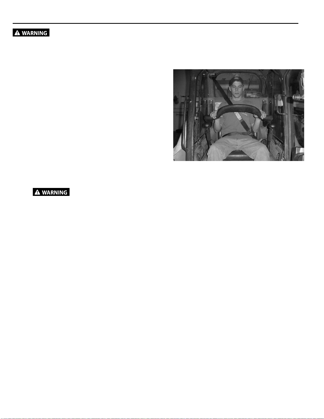
2. With the operator in the seat of the loader, the
seat belt fastened and the seat bar lowered (if so
equipped), start the engine.
To improve stability, always
carry attachment low to the ground while
driving.
3. Activate the auxiliary hydraulic system to start
the blade rotation. Make sure auxiliary hydraulic
circuit is operating in the correct direction.
IMPORTANT: Engine must be at idle speed
when engaging auxiliary hydraulic system.
IMPORTANT: This mower is designed to
operate from 30 to 42 gpm. Operating at higher
flow rates can cause serious damage to the
mower and will void the warranty.
IMPORTANT: Do not operate the brush mower if
excessive vibration is present. Serious damage
can occur. Check blades and gearbox.
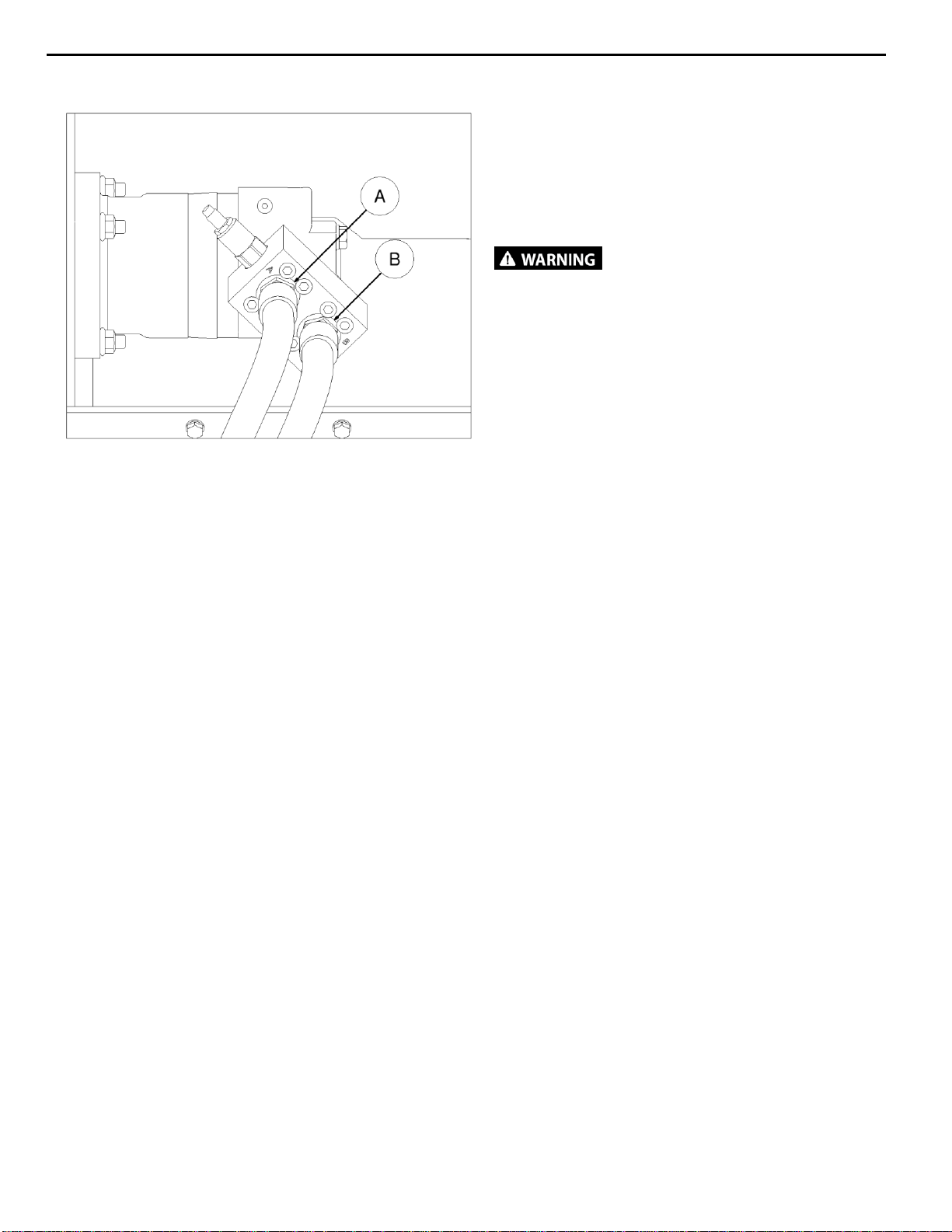
NOTE: Certain loaders may not operate in high
flow mode without special wire harnesses.
Others require the control switches to be
operated in a specific way. It may also be
necessary to switch the hose couplers around to
match your loader. (See loader’s operator’s
manual)
4. With the loader boom lowered all the way
and the auxiliary hydraulics engaged, slowly
rotate the loader coupler forward until the
skid plates are parallel to the ground.
NOTE: It may be helpful in certain instances
to keep the front of the mower raised slightly.
5. If desired, the loader lift arms can be put in
the float position. (See loader’s operator’s
manual.)
6. Drive the loader forward into the work area.
NOTE: Raising the front of the brush mower a
few inches may help while driving forward into
thick brush and when turning.

10
OPERATING INSTRUCTIONS
Brake Circuit
The mower is equipped with a shutdown braking
circuit that stops the blade rotation in an
abbreviated amount of time. This is controlled with
the pressure relief valve in the valve block.
Do not operate the brush mower
with the brake circuit disabled or if
malfunctioning. Never exit the loader when
the blade is still moving. If you think your
brake circuit is not functioning correctly have
it serviced.
IMPORTANT: Do not adjust the pressure relief
valve under any circumstances. This could cause
an unsafe braking condition and will void all
warranties.
IMPORTANT: Make sure the pressurized hose is
routed to the “A” port of the motor valve block. If it
isn’t, the mower will not operate.
See loader’s operator’s manual for details on
identifying the pressurized hydraulic coupler.
NOTE: If you are operating the loader controls
correctly and the mower still does not work, try
switching the hydraulic couplers around on the
mower lead hoses. This will effectively reverse
the flow to the motor.

11
___ _ROUTINE MAINTENANCE_________________
Lower the attachment to rest on the skid shoes and rear roller, shut down the engine,
relieve the hydraulic pressure to the attachment, wait for all motion to stop, and set park brake before
leaving the operator’s seat to perform service of any kind.
It is the operator’s responsibility to make daily inspections of the attachment and loader for damage, loose
bolts, fluid leaks, or anything else that could cause a potential service or safety problem. Preventive
maintenance is the easiest and least expensive type of maintenance.
IMPORTANT: Bolts and set screws can loosen after initial usage. After first hour of operation check all bolts
and set screws. This must also be done daily before operation. If nuts or bolts are missing or damaged,
replace immediately.
DAILY INSPECTION
Follow the rotary cutter service schedule for routine maintenance.
Check the following items every 4 hours of operation:
1. Check lift chain and shackle for damage or defects.
2. Check blades for cracks or damage. Replace in sets of three if necessary.
3. Check blade mounting hardware for proper torque of 1000ft. lbs. (1355Nm). Tap bolt head with
hammer and retorque.
4. Check all hardware. Retighten if necessary.
5. Check chains, deck, and shields. Repair if damaged or replace if necessary.
6. Check for damaged or missing decals. Replace if missing.
7. Check for damaged or leaking hydraulic hoses or fittings. Replace if necessary.
8. Clean debris, leaves, grass, and flammable material from deck area and under covers.
9. Check lubrication level in gearbox. Use 75W-90 gearlube or equivalent for ambient temperatures of
-5F to 60F. Use 85W-140 gearlube or equivalent for ambient temperatures of 40F to 120F.
Capacity is 60oz approximately.
10. Check that the antiskid treads are in good condition.
4
BLADE BOLTS

12
ROUTINE MAINTENANCE
Blade Inspection, Removal and Installation
Inspection:
1. Check that the blades can swing freely.
Also check blades, mounting hardware,
and stump jumper for wear, cracking, or
breakage, which can cause excessive
vibrations.
2. Replace if damaged.
Removal:
Only service the blades when brush mower is
attached to the loader.
1. Remove the (2) bolts securing the Blade
Nut Access Cover, and remove the cover.
2. Rotate the stump jumper until the bolt is
aligned with the access hole.
3. Remove the locknut from the blade bolt.
NOTE: Blade bolt and blade may fall from
the stump jumper when removing the blade
locknut. Always support the blade bolt and
blade while removing the locknut.
Installation:
1. Always use a new locknut and bolt during
assembly.
2. Tighten the locknut to 1000 ft. lbs. (1355
Nm) torque. Tap bolt head with a hammer
and retorque. Repeat procedure until the
locknut will not turn when torqued. Repeat
the procedure for the other blade.
NOTE: The blade bolt fits only one way into
the stump jumper. Install the washer
between the blade and the stump jumper.
Blade Carrier Removal
Before removing the blade carrier, make sure
the mower is held in a secure position. We
recommend tipping the mower up on its nose
with a hoist.
1. Remove the three bolts that retain the
cover.
2. Remove the nut locking plate and hub nut.
3. Secure the carrier with a chain hoist and
use a puller to free the carrier from the
gearbox shaft being sure not to let it fall.
NOTE: When reinstalling the hub nut,
torque to 800 ft-lbs.
Gearbox Fluid Check and Fill
1. Position the Brush Mower flat on the
ground.
2. Remove the top shield to gain access to
the gearbox cavity.
Moving parts may cause
injury or death. Always replace guard
after servicing. Do not operate without
cover in place.
3. Look at the oil level sight gauge on the
right side of the gearbox. Fluid must be
level with the check plug hole.
4. To add EP80W-90 or EP85W-140, remove
the fill plug and add lube until it is level with
the check sight gauge hole.
5. Reinstall the level check plug and the fill
plug, and clean up any oil that may have
spilled.
NOTE: Gearbox oil capacity is
approximately 60oz.
IMPORTANT: Fluids such as engine oil, gear
lube, and hydraulic fluid must be disposed of in
an environmentally safe manner. Some
regulations require that certain spills and leaks
be cleaned in a specific manner. Check local,
state, and federal regulations for the correct
disposal.

13
ROUTINE MAINTENANCE
Cleaning the Mower
To avoid injury or death,
before exiting under or servicing under the
attachment, be sure to disconnect the
auxiliary hydraulic hoses. Raise the lift
arms and tilt the attachment down fully.
Install an approved lift arm support and stop
the engine.
1. Position the attachment by raising the lift
arms and tilting the attachment down. Use
an arm lock when working with arms raised.
This may require the help of an assistant.
Refer to loader’s operator’s manual for arm
locking instructions. Keep the front edge of
the attachment within one foot of the ground
for debris clean out or blade service.
2. Exit the loader.
Always wear eye
protection that meets z87.1 when
cleaning.
3. Remove the top cover.
4. Use water or a small brush to clean debris
from the areas under the cover and around
the gearbox.
Use care when removing
any debris that is wrapped around the
blades, stump jumper, or gearbox shaft.
Blades can rotate suddenly.
5. Reinstall the top cover when clean.
Inspecting the Motor Coupler
1. Remove top shield.
2. Check the condition and tightness of the
set screw. Check for any looseness of fit
on the gearbox and motor shafts.
3. Replace as needed.
Moving parts may cause
injury or death. Always replace guard
after servicing. Do not operate without
cover in place.
Reversing Blade Rotation
The mower is equipped with double-sided
blades. When the original side gets worn down,
the valve block on the motor can be detached
and turned 180 degrees in order to change the
direction of rotation. The lead hoses do not
have to be removed to do this.
NOTE: You will have to remove the top shield
in order to access the valve block.
IMPORTANT: Take care not to lose or
damage the o-rings between the valve block
and the motor.
When both edges of the blade are excessively
worn, replace all blades.
Always replace worn blades.
Do not sharpen or weld on the blades.
Excesively worn blades can break and be
thrown hundreds of feet.
Always replace all blades with three that are
equal in weight to prevent vibration. Always
use genuine Erskinereplacement blades.

14
HEAVY DUTY MOWER PARTS INFORMATION________
ITEM
QTY
PART NO.
DESCRIPTION
STOCK NO.
1
1
314121
BODY 72" MEGA MOWER W/A (USED WITH RC100)
314156
BODY 72” MEGA MOWER W/A (USED WITH RC130)
2
1
314125
STUMP JUMPER MEGA MOWER W/A (FOR RC100)
300652
STUMP JUMPER MEGA MOWER W/A (FOR RC130)
300808
STUMP JUMPER FLANGED W/A (FOR RC130 FLNG)
3
314130
KIT PARTS BLADE MEGA MOWER
4
3
314065
NUT TOP LOCK 1-1/8 NF GRC
5
3
314061
WASHER HARD 1.25 ID X 4.438 OD
6
3
314126
BLADE MOWER 72 HD
7
3
314127
BOLT MOWER BLADE 5/8" THICK
9
1
314138
MOTOR HYD 11.9 CID
1
300823
MOTOR HYD 15 CID
10
6
38067
NUT HEX
TOP LOCK 3/4 NC GR9
11
1
314144
COUPLER MOWER 1.5X6T
PARTS ONLY
1
314178
COUPLER MOWER 1.5 X 1-3/4 20T
12
1
314113
COVER BOLT ACCESS PAINTED
13
1
314154
COVER MEGA MOWER W/A
14
3
202153
TAPE ANTI-SKID 2 X 16 DIE CUT
15
1
300599
NUT CASTLE M30-2 FLGD (USED WITH RC100)
1
300660
NUT CASTLE 1-1/4-14 UNS FLGD (USED WITH RC130)
18
2
103116
BOLT HEX
3/8 X 1 NC GR5
19
6
15363
BOLT HEX
3/4 X 2-1/2 NC GR8 YZ
20
14
103880
WASHER LOCK
3/8"
21
4
13212
BOLT HEX
1/2 X 2-1/4 NC GR5
22
1
37214
NUT HEX
LOCK 1/2 NC
24
1
400462
CHAIN LINK 5/16 X 5 FT
23
4
0167011
NUT FLG TOP LOCK
1/2 NC GR 8
25
1
400463
SHACKLE SCREW PIN 3/8
26
1
33012
WASHER FLAT
1/2"
27
1
13210
BOLT HEX
1/2 X 1-3/4 NC GR5
28.1
2
314075
HOSE 3/4 X 82 12MB-12FJX (LEAD)
RED ZIP TIE TO PORT A
29
8
23313
BOLT SHCS 3/8 X 2-1/2 NC PLAIN
OBSOLETE
8
23315
BOLT SHCS 3/8 X 3 NC
REPLACED 23313
30
1
314199
SHIELD HUB W/A OBSOLETE
31
3
13365
BOLT HEX (USE THREAD LOCKER) OBSOLETE
3/4 X 3 NC GR5
32
3
33632
WASHER LOCK OBSOLETE
3/4"
33
1
314128
GEARBOX RC100 OBLT
PARTS ONLY
1
300593
GEARBOX RC130 –6T OBSOLETE
PARTS ONLY
1
300667
GEARBOX RC130 –20T OBSOLETE
1
300817
GEARBOX RA RC130 1:1.43 20T FLNG (60oz of 80W-90)
34
6
15364
BOLT HEX 3/4 X 2-3/4 NC GR8
REPLACED 15365
6
15365
BOLT HEX 3/4 X 3 NC GR8
35
1
330958
VALVE ASSM RELIEF MANI MNT W/C
REPLACED 300822
1
300822
VALVE ASSM RELIEF MANI MNT W/C OBSOLETE
REPLACED 314157
1
314157
VALVE BLOCK ASSM OBSOLETE
35.1
1
300291
VALVE RELIEF OBSOLETE
1
300795
VALVE RELIEF
35.2
1
330814
ADPT STR 12MB-12FB CHECK
36
2
314155
O-RING - 1" X 1/8" (USE WITH VALVE 300822 ONLY)
OBSOLETE
37
1
300574
PLATE NUT LOCK 1.81 HEX OBLT (USED WITH RC100)
1
300575
PLATE NUT LOCK 2.00 HEX OBLT (USED WITH RC130)
1
300728
PLATE NUT LOCK 2.0 HEX W/A (REPLACES 300575)
38
6
33864
WASHER FLAT USS 3/4 GR 8 OBSOLETE
(USED WITH 15365)
39
6
33898
WASHER LOCK 3/4 GR 8
41
12
13107
BOLT HEX
3/8 X 1-1/4 NC GR5

15
HEAVY DUTY MOWER PARTS INFORMATION
OLD STYLE

16
GENERAL SPECIFICATIONS
Model
Mega Mower
Mounting Plate
Universal
Hydraulic Pump Capacity Requirements
30 to 42 GPM
Operating Weight
1535 lbs.
Cutting Diameter
72”
Cutter Capacity
material up to 6”
Overall Width
77”
Overall Length
85.5”
Overall Height
30”

17
____________________________________________________
____________________________________________________
____________________________________________________
____________________________________________________
____________________________________________________
____________________________________________________
____________________________________________________
____________________________________________________
____________________________________________________
____________________________________________________
____________________________________________________
____________________________________________________
____________________________________________________
____________________________________________________
____________________________________________________
____________________________________________________
____________________________________________________
____________________________________________________
____________________________________________________
____________________________________________________
____________________________________________________
____________________________________________________
____________________________________________________
____________________________________________________
____________________________________________________
____________________________________________________
____________________________________________________
____________________________________________________
____________________________________________________
____________________________________________________
____________________________________________________
____________________________________________________
____________________________________________________
NOTES

18
____________________________________________________
____________________________________________________
____________________________________________________
____________________________________________________
____________________________________________________
____________________________________________________
____________________________________________________
____________________________________________________
____________________________________________________
____________________________________________________
____________________________________________________
____________________________________________________
____________________________________________________
____________________________________________________
____________________________________________________
____________________________________________________
____________________________________________________
____________________________________________________
____________________________________________________
____________________________________________________
____________________________________________________
____________________________________________________
____________________________________________________
____________________________________________________
____________________________________________________
____________________________________________________
____________________________________________________
____________________________________________________
____________________________________________________
____________________________________________________
____________________________________________________
____________________________________________________
____________________________________________________
NOTES

19
LIMITED WARRANTY
Erskine Attachments, LLC warrants each new machine manufactured by us to be free from
defects in material and workmanship for a period of twelve (12) months from date of delivery to
the original purchaser.
Our obligation under this warranty is to replace free of charge, at our factory or authorized
dealership, any part proven defective within the stated warranty time limit.
All parts must be returned freight prepaid and adequately packaged to prevent damage in
transit.
This warranty does not cover:
1. New products which have been operated in excess of rated capacities or negligence
2. Misuse, abuse, accidents or damage due to improperly routed hoses
3. Machines which have been altered, modified or repaired in any manner not
authorized by our company
4. Previously owned equipment
5. Any ground engaging tools in which natural wear is involved, i.e. tooth tips, cutting
teeth, etc
6. Normal maintenance
7. Fork tines
8. Hydraulic motors that have been disassembled in any manner
In no event will the Sales Representative, Dealership, Erskine Attachments, LLC, or any other
company affiliated with it or them be liable for incidental or consequential damages or injuries,
including but not limited to the loss of profit, rental or substitute equipment or other commercial
loss. Purchaser’s sole and exclusive remedy being as provided here in above.
Erskine Attachments, LLC must receive immediate notification of defect and no allowance will
be made for repairs without our consent or approval.
This warranty is in lieu of all other warranties, express or implied by law or otherwise, and there
is no warranty of merchantability or fitness purpose.
No agent, employee, or representative of Erskine Attachments, LLC has any authority to bind
Erskine Attachments, LLC to any warranty except as specifically set forth herein. Any of these
limitations excluded by local law shall be deemed deleted from this warranty; all other terms
apply.
This warranty may not be enlarged or modified in any manner except in writing signed by an
executive officer of Erskine Attachments, LLC to improve its products whenever it is possible
and practical to do so. Erskine Attachments, LLC reserves the right to make changes and or
add improvements at any time without incurring any obligation to make such changes or add
such improvements to products previously sold.
Erskine Attachments, LLC
P.O. Box 1083 Alexandria, MN 56308
Phone (218) 435-4045

20
P/N 300471 Date Printed: 10/30/2018
Erskine Attachments LLC Printed in U.S.A.
Table of contents
Other Erskine Attachments Lawn Mower manuals