EXPEDITION UPFITTER EXUP-B Service manual
Popular Boiler manuals by other brands

Sime
Sime MURELLE HE 70 R ErP User, installation and servicing instructions
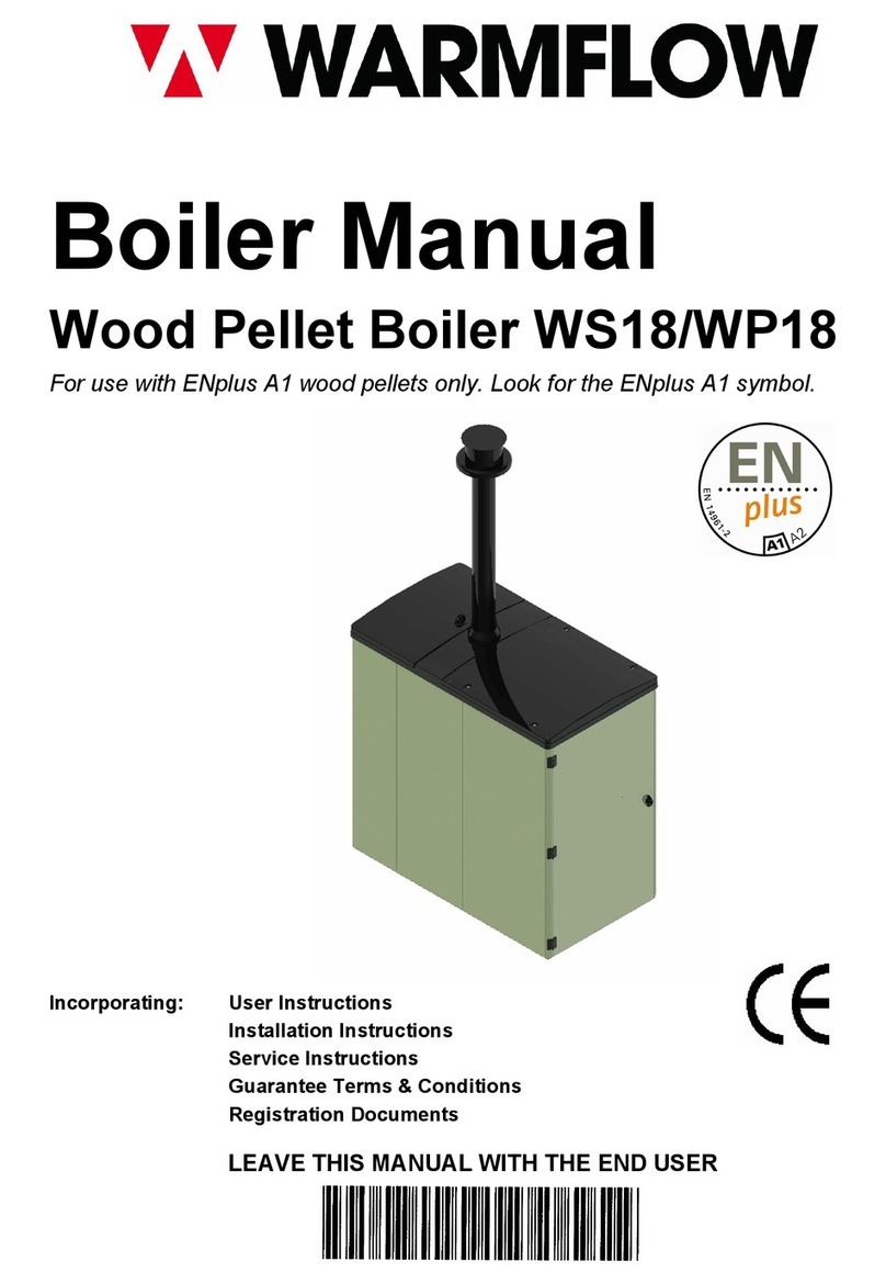
WarmFlow
WarmFlow WS18 instruction manual
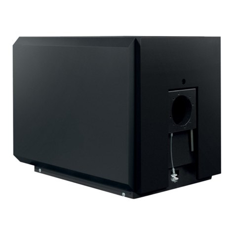
Hamworthy
Hamworthy Ensbury LT 70 INSTALLATION AND ASSEMBLY INSTRUCTIONS INSTALLATION AND ASSEMBLY INSTRUCTIONS
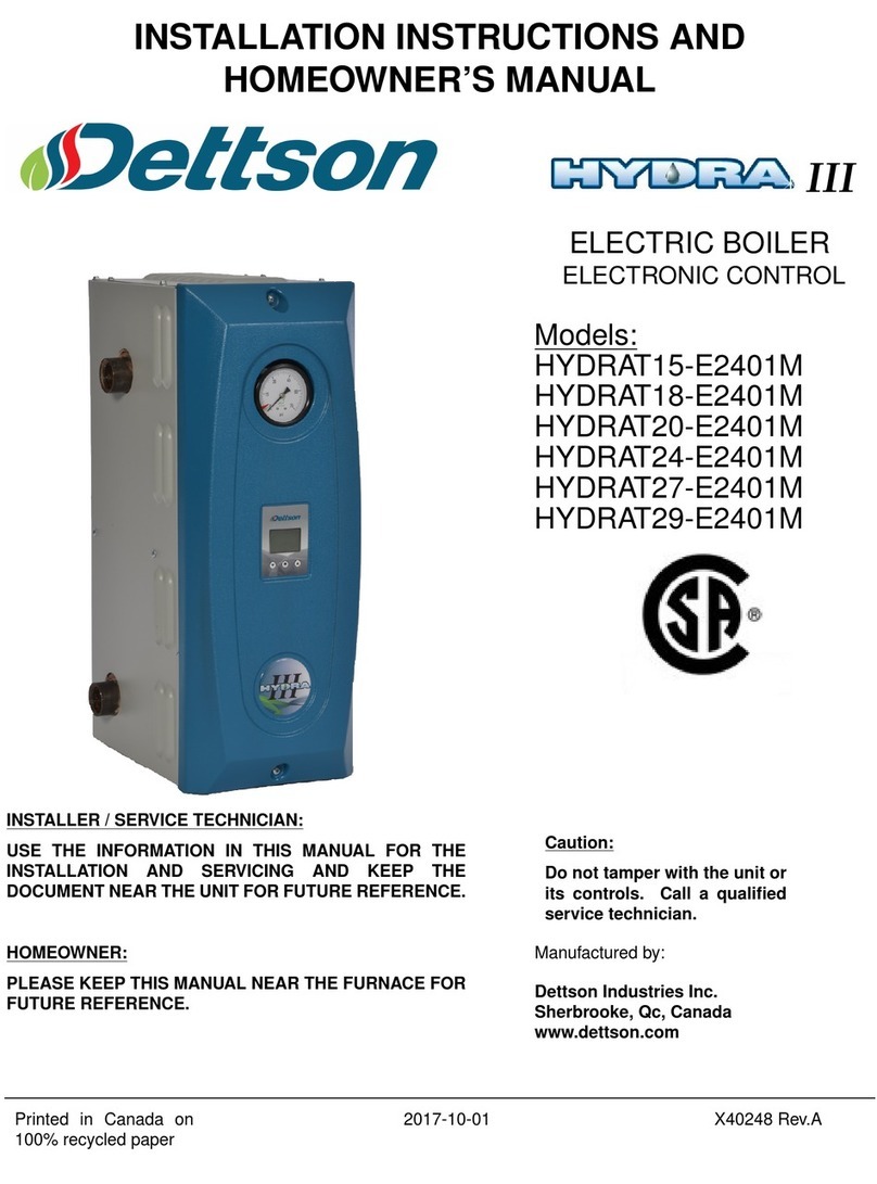
Dettson
Dettson HYDRAT15-E2401M Installation instructions and owner's manual
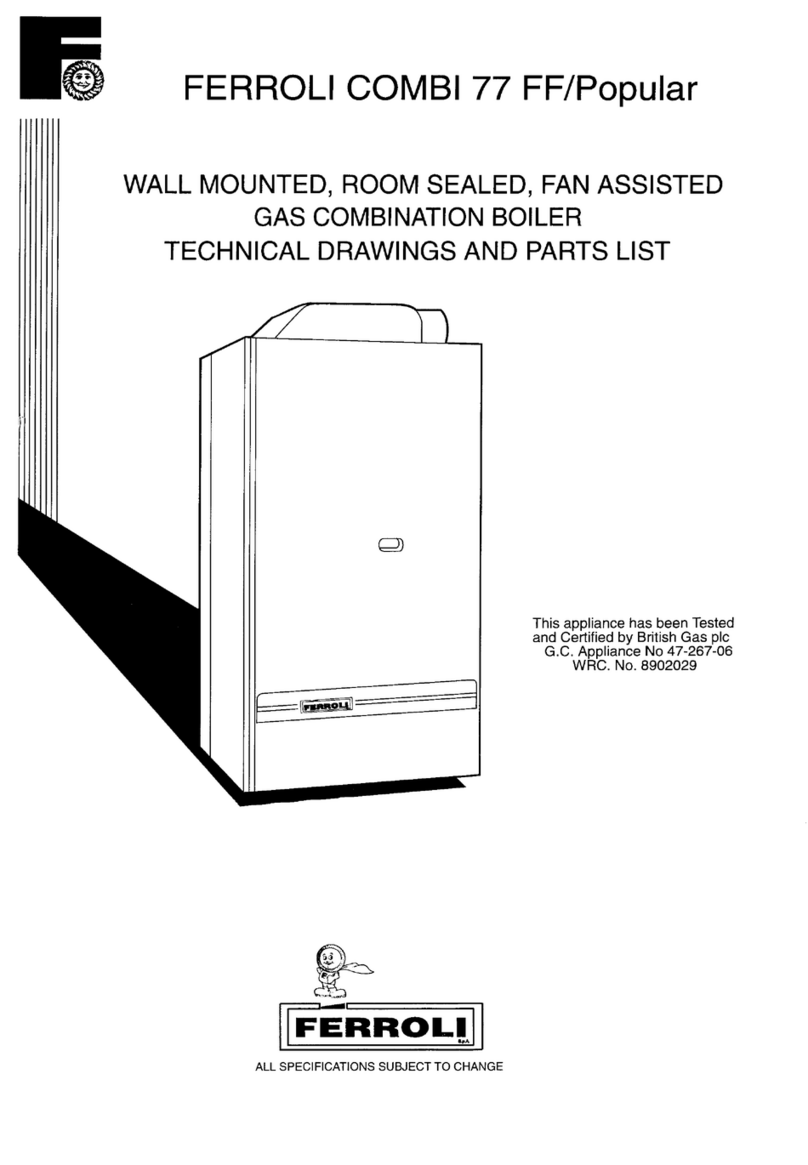
Ferroli
Ferroli Combi 77 FF Installation

Hoval
Hoval UltraOil 65 Technical information installation instructions

Stanley
Stanley Tara Installation and operating instructions
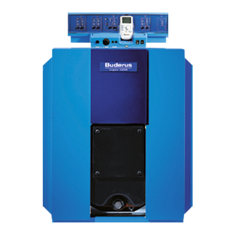
Buderus
Buderus Logano GE315 Installation and maintenance instructions
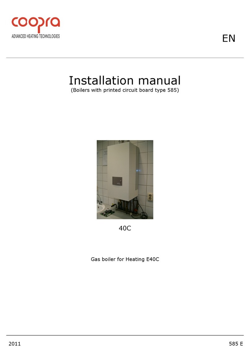
Coopra
Coopra 40C installation manual
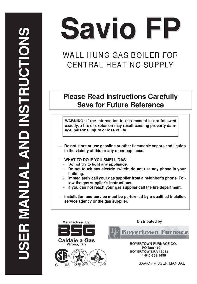
bsg
bsg Savio FP User manual and instructions

Viessmann
Viessmann VITODENS 333 Service instructions
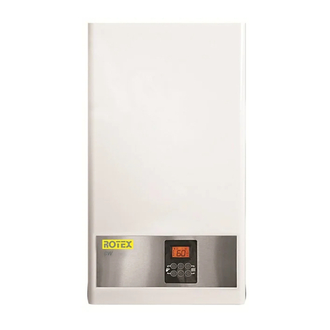
Rotex
Rotex GW Installation and operating instructions

HearthStone
HearthStone H series instruction manual
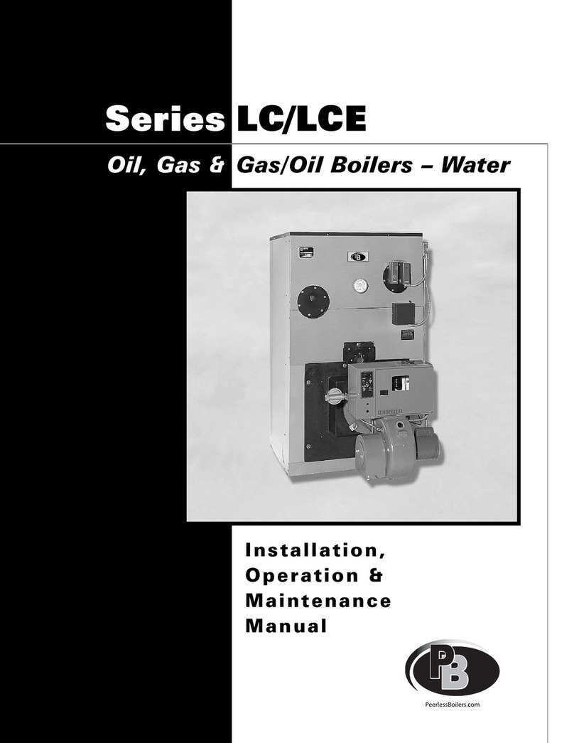
PeerlessBoilers
PeerlessBoilers LC Series Installation, operation & maintenance manual
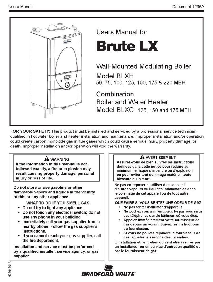
Bradford White
Bradford White Brute LX BLXCW-125 user manual
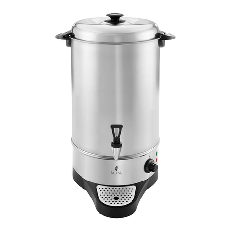
Royal Catering
Royal Catering RCWK 10A user manual
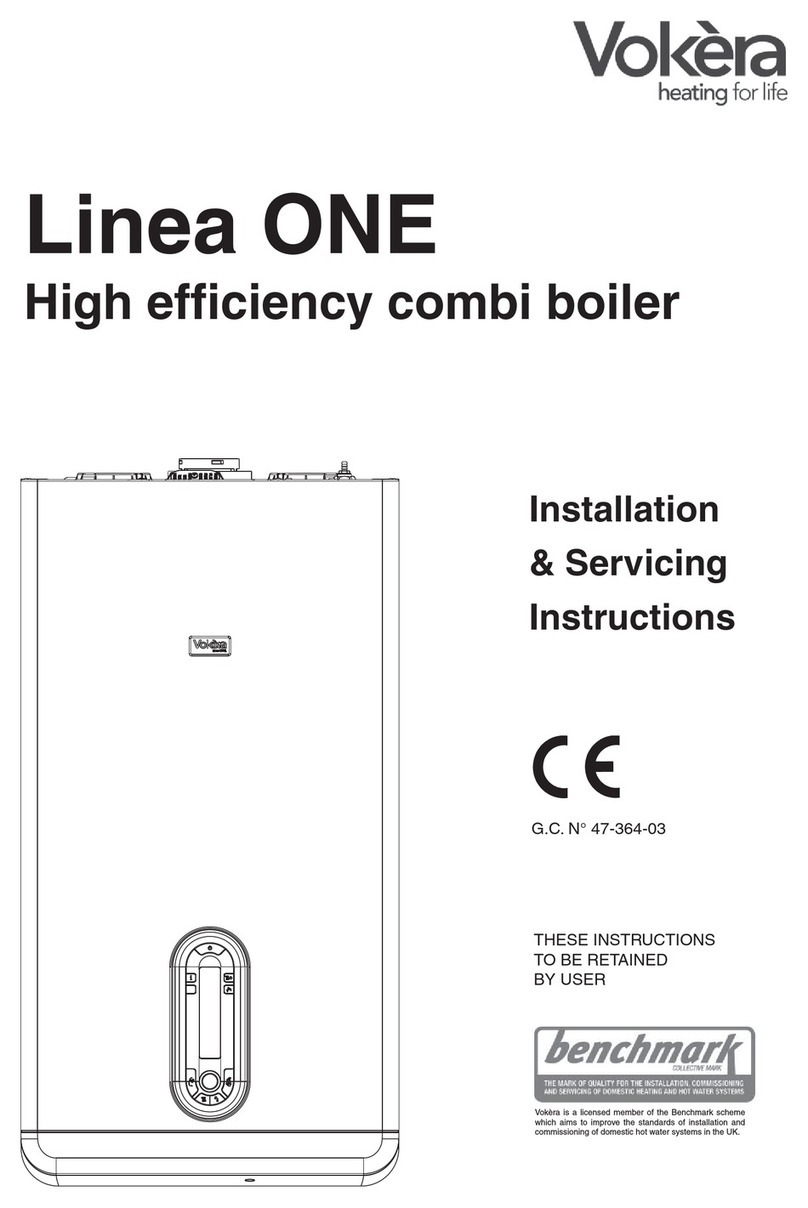
VOKERA
VOKERA Linea Installation & servicing instructions
Unical
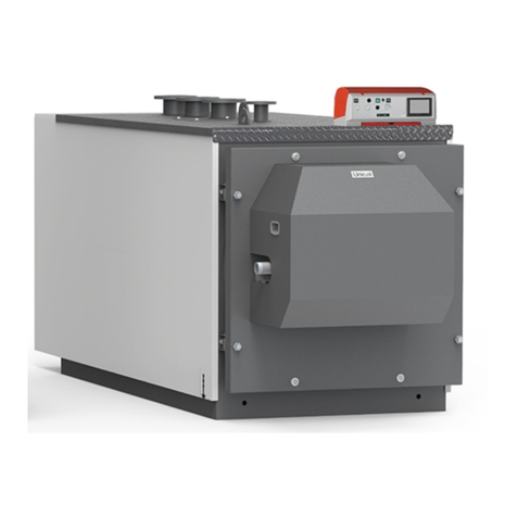
Unical SPK 1000 Installation and maintenance instructions


