EyeView Gpower-S3PIR Manual

IP Speed Dome
Hardware Installation
Guide
Ver. 070906

Table of Contents
1INTRODUCTION............................................................................................. 1-1
1.1 Package Contents................................................................................................1-1
1.2 Features and Benefits..........................................................................................1-2
1.3 Safety precautions...............................................................................................1-3
1.4 Warning indications for use...............................................................................1-3
1.5 Environmental requirements.............................................................................1-3
1.6 Precautions on installation.................................................................................1-4
2H/W Installation Procedure ............................................................................. 2-6
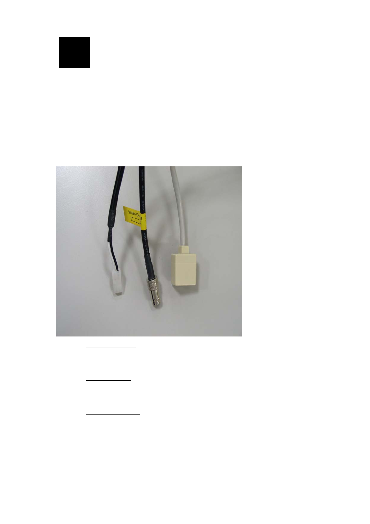
2.1 Connections .........................................................................................................2-6
2.1.1 Indoor connections ........................................................................................................2-6
2.1.2 Outdoor connections......................................................................................................2-7
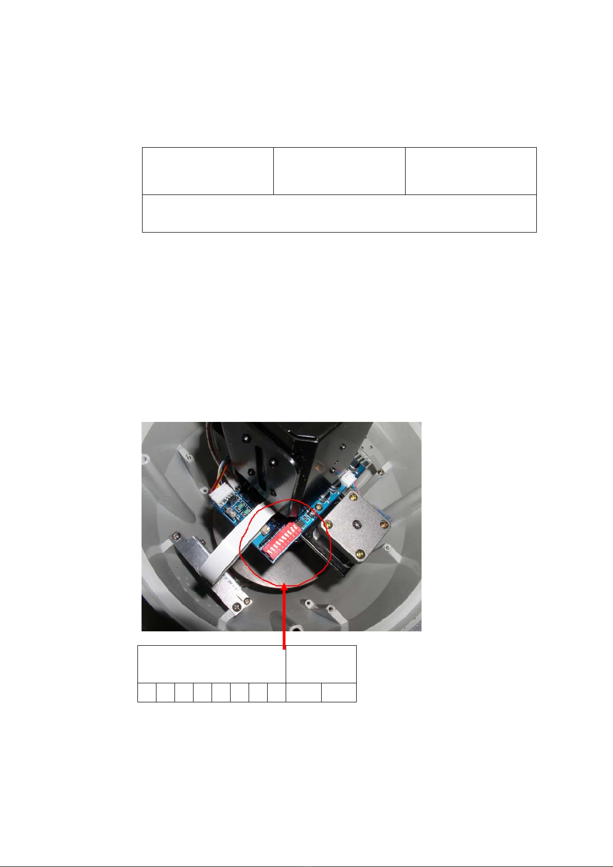
2.2 Speed dome set up...............................................................................................2-8
2.2.1 Setup camera ID, baud rate and protocol.......................................................................2-8
2.3 Indoor H/W Installation Procedures...............................................................2-10
2.3.1 Indoor installation........................................................................................................2-10
2.4 Outdoor H/W Installation Procedures............................................................2-11
2.4.1 Understand Outdoor applications ................................................................................2-11
2.4.2 Install the mount ..........................................................................................................2-12
2.4.3 Connect the housing to the mount ...............................................................................2-14
2.5 Detailed dimensions ..........................................................................................2-16
2.5.1 Outdoor Housing .........................................................................................................2-16
2.5.2 Outdoor Wall mount....................................................................................................2-17
2.5.3 Outdoor Ceiling mount................................................................................................2-18
2.5.4 Outdoor Corner mount.................................................................................................2-19
2.5.5 Outdoor Pole mount.....................................................................................................2-20
3Appendix.......................................................................................................... 3-21
3.1 Camera ID Set up..............................................................................................3-21

1INTRODUCTION
1
1.1 Package Contents
Indoor Outdoor
Power Core (for Indoor) Software CD
Adapter (for Indoor) Power Box (for Outdoor)
1-1

1-2
1.2 Features and Benefits
zMPEG-4 compression gives a high resolution image quality
The IP speed dome offers an optimal combination of network, digital,
and optical technology. The IP Speed Dome adopts MPEG-4 ASP
compliant compression technology which compress video analog into
video streaming while maintaining resolution up to full-D1, 30 fps.
Building in with LAN/WAN ports, the IP Speed Dome applies QoS
(Quality of Service) technology to fully utilize the network bandwidth.
Meanwhile, IP Speed Dome also supports multicast video streaming
technologies to fulfill almost unlimited on-line video requests.
zRemote control from any place at any time
The IP Speed Dome Series adopts ARM9 SoC base embedded system
and web server which enables remote control of the camera. Through
bundled AP, you can pan/tilt/zoom the camera, set up motion detection
to a specified area, perform tour monitoring, set up different video
resolutions, etc. In addition, features such as tour surveillance, alarm
and further enhance the usefulness of IP Speed Dome Series to make
your remote surveillance more flexible and more responsive to
different situations or environments.
zHigh quality and reliability in both optics and mechanism
With a cleverly designed pan/tilt mechanism and an industrial-grade
slip ring, the IP speed dome accurate auto zoom system, and powerful
352X zoom capability.

1-3
1.3 Safety precautions
1. Select a proper location and use safe hoist for installing speed dome
cameras.
2. Confirm that the hoist is capable of lifting to the installation position.
3. Proper protective measures must be provided in the hoist, for protecting
engineering staffs.
4. Confirm that power supply is 110V/220V. Ensure safety precautions for
preventing electric shock.
1.4 Warning indications for use
1. Local electrical appliance regulations must be observed for using this
product.
2. The outdoor model uses AC24V, while the indoor model uses DC15V.
For safety of use, do not use any power supply other than that specified.
3. For the safety of the engineering staffs, apply power only upon
completion of installation.
1.5 Environmental requirements
1. Environmental requirements for indoor type speed dome cameras:
zEnvironment temperature: -10°C to +40°C
zEnvironment humidity: <90%
zPower supply: DC15V, 2A, 50/60Hz
2. Environmental requirements for outdoor type speed dome
cameras:
zEnvironment temperature: -40°C to +50°C
zEnvironment humidity: <90%
zPower supply: AC24V, 2A, 50/60Hz

1-4
1.6 Precautions on installation
1. Basic requirements for installation
zFollow local regulations about installation safety request.
zCheck out if accessories are complete. Optional accessories are
required for different installation sites. Please contact your local
distributors for proper installation accessories, so that the camera
could be installed safely without causing danger.
2. Check if the installation location is of sufficient height.
3. Check if the installation location is strong enough for supporting
cameras. Make sure installation spots (ceiling or wall) is of
sufficient strength to support the camera and bracket without
immediate danger of falling.
4. Setting of Camera Position Code
Setup your camera ID address and communication protocol prior to
installation. In order to make a new setting valid, please shut down the
power before re-setting.
5. Self Test of Camera
The camera is available with the following self test. Carry them out
prior to installation. After connecting power, speed dome camera will
turn 90 degrees down vertically, then start horizontal scanning. This will
last for 20-30 seconds. Speed dome camera will then stop at the Preset
Position 1. On completion of these, the speed dome camera is in normal
condition.
6. Please keep the original packaging
After unpacking the camera, take good care of the original packaging. In
case any problem occurred, it can be used to re-pack cameras for
returning to the local distributor or manufacturer for repair.
7. Remove protection materials before supplying power to the camera,
so as to prevent it from faulty operation or causing mechanical
errors. See the following illustration.

8. This product is normally installed in an elevated position.
Installation work should comply with local safe regulations.
9. Proper safety precautions and protective measures shall be taken
for installing the camera.
10. For the personnel safety sake, carry out electrification and product
test only after completion of installation work.
1-5

2H/W Installation Procedure
2
2.1 Connections
Indoor IP speed dome connection is different from the outdoor IP speed dome.
Follow the description below to connect to respective apparatus.
2.1.1 Indoor connections
1. Video-out cable
Connect it to the video-in port of respective apparatus. The signal is 75Ω
Composite Video Signal.
2. DC wire cable
Connect this DC wire cable to the board on power box for 15V DC,2.0A
voltage input.
3. LAN/WAN cable
This cable is used for LAN/WAN via a standard RJ45 connector.
Supporting NWAY, this video server can auto detect the speed of local
network segment (10Base-T/100Base-TX Ethernet). WAN is for FTTH and
connects to a xDSL or cable modem.
2-6

2.1.2 Outdoor connections
1. Power input
Connect this jack to the power supply of 110VAC or 230VAC according to
the product you bought.
Power Input -
Wire Connection
needed
2. RJ45 Cable Connection
Connect the RJ45 port from housing cable to another RJ45 network cable
for LAN/WAN inside the power box.
3. Video-Out Cable Connection
Connect the Video-Out cable from housing to another BNC cable for video
image inside the power box.
4. Housing Power Cable Connection
Connect the power cable from housing to the board inside of the power box
*Notice
Before having RJ45 cable connected to the RJ45 port, one must first have both RJ45 cables
through the cable glands inside the power box without the cable connector and RJ45 port
connector first, and then you make the connector from there. ( Because the RJ45 with
connector or the port connector can’t fit through to the cable glands) Please tighten the
glands firmly by hand first and after that use tool to tighen the knot for another 1/2 turn. Do
not over-tighten the glands for long life span purpose
2-7

2.2 Speed dome set up
Follow the description below setup IP speed dome’s hardware camera ID,
baud rate and protocol.
Speed dome setup Video platform setup
AP (NVR2) setup
Camera ID, baud rate and protocol setting in these 3 item should be the same
for PTZ control function to work.
2.2.1 Setup camera ID, baud rate and protocol
Loosen the four screws and de-attached the dome cover from the housing.
Follow the tables below to setup each respective parameter. A 10-position
DIP SWITCH is furnished on the camera control board. SW1~ SW8 are for
ID address setting and SW9/SW10 are for protocol setting. Respective
setting is illustrated in the following table:
2-8
Address ID Protocol/
Baud Rate
1 2 3 4 5 6 7 8 9 10
Setting of camera ID Address and
Communication Protocol

2-9
●Protocol and baud rate switch
SW9 SW10
PELCO D-2400 OFF OFF
PELCO P-4800 ON OFF
PELCO P-9600 OFF ON
EYEVIEW
(Recommended)
ON ON
●Camera ID address setting
Please refer to the Appendix. A “Camera hardware ID setup”

2.3 Indoor H/W Installation Procedures
2.3.1 Indoor installation
1. Installing the camera:
Take out the camera upper casing, as shown below:
Wall mount
Pandent mount
2. Wiring
After completion of the above works, connect the wires for video /
DC15 V Power Input/ LAN/WAN.
3. Electrification test
zBefore connecting the power, make a final check to confirm correct
wiring.
zAfter electrification, the camera will undertake an automatic
self-test. This routine consists of vertical scanning following by
horizontal scanning. Then the camera automatically swings to
Position 1. This concludes the initialization of self-test.
4. Install the dome cover
Finishing all the above, the transparent dome cover can be installed.
Make sure the screws are driven tightly.
2-10

2.4 Outdoor H/W Installation Procedures
There are 4 kinds of outdoor application. And each of them requires two
steps to install the outdoor IP speed dome. Please refer to the picture below
to understand each application type.
Then follow the procedure below to install it.
2.4.1 Understand Outdoor applications
zOutdoor Wall mount
Outdoor Housing + outdoor Wall mount
zOutdoor Ceiling mount
Outdoor Housing + outdoor Ceiling mount
2-11

zOutdoor Corner mount
Outdoor Housing + outdoor Wall mount + outdoor Corner
bracket
zOutdoor Pole mount
Outdoor Housing + outdoor Wall mount + outdoor Pole bracket
2-12
2.4.2 Install the mount
The mounting wall must be strong enough for holding the camera.
Minimum loading capacity should be at least 35 kg or above, for prevention
of fall and personal injury.
zMark the 4 mounting hole centers according to the mount base plate, as

shown below:
200mm
170mm
140mm
114mm
zDrill 4 holes Ø 6.5mm:
zUse the 4 screws provided to fix the mount on the wall
2-13

2.4.3 Connect the housing to the mount
zInsert the cable from the housing through the hole. There’s some
lubricating oil inside the tube, thus the cable would have some oil on it
once inserted through the Tube.
zThen take out M6 screws and hexagonal wrench provided within the
package and fasten the 4 screws as pictue below.
2-14

zConnect the housing cable to the board in the junction box
zConnect the junction box to respective apparatus.
Please refer to Page 2-17 for how to connect.
2-15

2.5 Detailed dimensions
2.5.1 Outdoor Housing
2-16

2.5.2 Outdoor Wall mount
2-17

2.5.3 Outdoor Ceiling mount
2-18
Table of contents