Fa-Ga SAMURAI B 200 User manual

WMV-Dresden
WMV-Dresden
WMV-Dresden
WMV-Dresden
WMV-Dresden
WMV-Dresden
WMV-Dresden
WMV-Dresden
WMV-Dresden
WMV-Dresden
WMV-Dresden
WMV-Dresden
WMV-Dresden
WMV-Dresden
WMV-Dresden
WMV-Dresden
WMV-Dresden
WMV-Dresden
WMV-Dresden
WMV-Dresden
WMV-Dresden
WMV-Dresden
WMV-Dresden
WMV-Dresden
WMV-Dresden
WMV-Dresden
WMV-Dresden
WMV-Dresden
WMV-Dresden
WMV-Dresden
WMV-Dresden
WMV-Dresden
WMV-Dresden
WMV-Dresden
WMV-Dresden
WMV-Dresden
INSTRUCTIONS
ASSEMBLY AND OPERATING
Safety Effi cacy Quality
SAMURAI
Models:
B 200
B 230
B 250
B 180
K 210
K 250
D 105
D 180
Riding Mower
Version without STVZO
approval for road travel
Road-travel TÜV–approved
version available on request
at different price.
Please study this manual before you
operate the machine!
WMV-Dresden, Ersatzteilservice für Elektrowerkzeuge, Motor- und Gartengeräte

WMV-Dresden
WMV-Dresden
WMV-Dresden
WMV-Dresden
WMV-Dresden
WMV-Dresden
WMV-Dresden
WMV-Dresden
WMV-Dresden
WMV-Dresden
WMV-Dresden
WMV-Dresden
WMV-Dresden
WMV-Dresden
WMV-Dresden
WMV-Dresden
WMV-Dresden
WMV-Dresden
WMV-Dresden
WMV-Dresden
WMV-Dresden
WMV-Dresden
WMV-Dresden
WMV-Dresden
WMV-Dresden
WMV-Dresden
WMV-Dresden
WMV-Dresden
WMV-Dresden
WMV-Dresden
WMV-Dresden
WMV-Dresden
WMV-Dresden
WMV-Dresden
WMV-Dresden
WMV-Dresden
- 2 -
Please contact your local FA-GA dealer for additional
questions regarding operation and assembly!
Contents Page
3
4 - 8
9 - 10
11 - 16
17
18
19
19 - 21
22 - 26
27
28 - 45
1.1 Safety instructions
1.2 Assembly and Setup
1.3 Safety devices and warning symbols on the machine
1.4 Operation
1.5 Technical specifications
1.6 Electric Deployment System
1.7 Dashboard
1.8 Overview
1.9 Maintenance
1.10 Service interval chart
1.11 Spares/Parts list
Info
Info
This manual contains descriptions and important information on safe and
proper operating and maintaining practice of your riding mower.
Make sure to familiarize with the information given under the section „safety
instructions“ and to assure full compliance with all safety rules listed.
The section „maintenance“ contains all details on periodic and preven-
tive care as well as lubrication and adjustment operations required on the
machine.
Because of on-going product improvements, the pictures in this document
may not reflect the current look of your riding tractor. However, this won‘t
affect any of the basic operating, assembly and maintenance criteria that
remain unchanged.
WMV-Dresden, Ersatzteilservice für Elektrowerkzeuge, Motor- und Gartengeräte

WMV-Dresden
WMV-Dresden
WMV-Dresden
WMV-Dresden
WMV-Dresden
WMV-Dresden
WMV-Dresden
WMV-Dresden
WMV-Dresden
WMV-Dresden
WMV-Dresden
WMV-Dresden
WMV-Dresden
WMV-Dresden
WMV-Dresden
WMV-Dresden
WMV-Dresden
WMV-Dresden
WMV-Dresden
WMV-Dresden
WMV-Dresden
WMV-Dresden
WMV-Dresden
WMV-Dresden
WMV-Dresden
WMV-Dresden
WMV-Dresden
WMV-Dresden
WMV-Dresden
WMV-Dresden
WMV-Dresden
WMV-Dresden
WMV-Dresden
WMV-Dresden
WMV-Dresden
WMV-Dresden
- 3 -
Safety instructions
1.1 Safety Tips
- Operators of the lawn tractor must be age 16 or older.
- This machine was designed in strict compliance with all applicable rules and meets
all safety specifications for proper machine use. However, this is a powerful piece of
equipment that can cause injury or even be permanently damaged if not properly
operated and maintained.
- Make sure to keep thirds at least 10 meters away from the mowing and trimming
area to protect bystanders from thrown objects.
- Only operate your riding mower after having made sure that the machine and all
other attachments and supplies as well as all safety devices are in place and well-
working. Read the operator manual to familiarize yourself with the mower and
controls! Strictly use your mower for selected proper applications. Users will be
entirely liable for damages and injuries resulting from misuse and unsuitable
application.
- Keep all safety features properly maintained, follow the operator’s manual and
warning decals and be safety conscious.
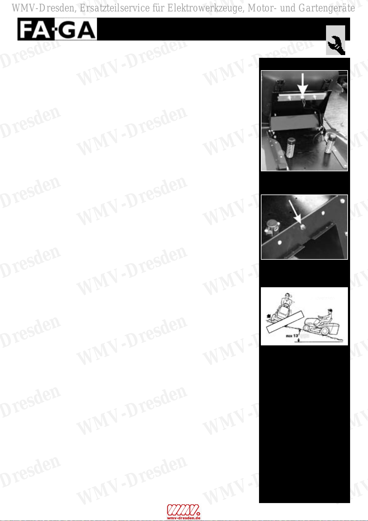
- Always mow slopes up and down so the tractor wont tip sideways. Avoid operating
on steep slopes or near ditches to prevent overturning and comply with the tractor
safety warnings.
- Lawn riding tractors with ignition engine must be strictly started and used outdoors
to avoid danger of carbon monoxide poisoning.
- Immediately stop the mower any time you suspect that some fault has occurred in
the machine. Eventually contact your dealer or any other qualified servicing dealer to
let the tractor be overhauled and repaired, if needed.
- Give the hydraulics and the various pipes a thorough check before starting the
mower. Strictly let eventual damaged parts be fixed by a qualified servicing dealer.
- Never attempt to adjust or change the operating hydraulic pressure of your lawn
mower.
- Altering your lawn tractor or replacing any part of it with non-original spares will
invalid your warranty and fail the general requirements for proper operating
conditions!
IMPORTANT
The mower’s hydraulic system is ready to go when engine warm-up is complete and
the oil temp has reached 18° C. So let the hydraulic oil circulate and warm-up when the
engine starts running.
WARRANTY DETAILS
All SAMURAI lawn riding mowers are covered by Farm & Garten – STM Vertriebs GmbH
with the following warranties:
2 years warranty for home-owners and residential users
1 year warranty for landscapers, commercial, institutional, rental and on-farms users
The warranty does not apply to consumable parts such as drive belts, brake pads,
mower blades, blades fixation screws and nuts, turf delivery angle plates, screws,
nuts, tires and sliding bearings.
WMV-Dresden, Ersatzteilservice für Elektrowerkzeuge, Motor- und Gartengeräte

WMV-Dresden
WMV-Dresden
WMV-Dresden
WMV-Dresden
WMV-Dresden
WMV-Dresden
WMV-Dresden
WMV-Dresden
WMV-Dresden
WMV-Dresden
WMV-Dresden
WMV-Dresden
WMV-Dresden
WMV-Dresden
WMV-Dresden
WMV-Dresden
WMV-Dresden
WMV-Dresden
WMV-Dresden
WMV-Dresden
WMV-Dresden
WMV-Dresden
WMV-Dresden
WMV-Dresden
WMV-Dresden
WMV-Dresden
WMV-Dresden
WMV-Dresden
WMV-Dresden
WMV-Dresden
WMV-Dresden
WMV-Dresden
WMV-Dresden
WMV-Dresden
WMV-Dresden
WMV-Dresden
- 4 -
- 4 -
Assembly and Setup
1.2 Assembly and Setup
Before you start the equipment, make sure that oil in the crankcase and in the hydraulic
line is filled to the right level, that all safety controls and devices are in place and well-
working and that the mower blades are properly sharp.
For easier transport and storage purposes some parts of the mower do not come ready
mounted on the mower and need to be assembled by the operator after removing the
mower from the crate. Follow the instructions below to perform final assembly of all
parts.
CAUTION
Due to handling safety reasons lawn riding mowers are supplied without any gas fill.
Before starting the engine, fill the gas tank and check the oil level both in the crank-
case and in the hydraulic tank. If required, fill new oil up before starting the mower.
(see section 1.9 „Maintenance“ of these instructions)
Should you wish to retrofit or equip your SAMURAI mower with a ROLL OVER PROTEC-
TION SYSTEM (ROPS), please be reminded that this is an optional implement that only
fits professional seat versions!
Standard lawn mower supplies include:
- SAMURAI lawn riding mower
- Steering wheel with jam nut Ø 6 x 40
- Operator‘s seat (different types for different models) with fixation bolts and screws
- Collector bin (loose parts) or free discharge
- Wheel pulling screw
- Operating and maintenance instructions
- 2 sets of starter keys
UNPACKING
When taking the mower out of the packing crate, make sure to collect all loose parts
and accessories so that no bulk pieces get lost.
Before letting the mower roll off the pallet, make sure that the mowing lifter handle on the
righthand rear wheel (see Fig. 1.2.1) is pulled all the way back to avoid damaging the cut-
ting deck or the blades.
Fig. 1.2.1
WMV-Dresden, Ersatzteilservice für Elektrowerkzeuge, Motor- und Gartengeräte

WMV-Dresden
WMV-Dresden
WMV-Dresden
WMV-Dresden
WMV-Dresden
WMV-Dresden
WMV-Dresden
WMV-Dresden
WMV-Dresden
WMV-Dresden
WMV-Dresden
WMV-Dresden
WMV-Dresden
WMV-Dresden
WMV-Dresden
WMV-Dresden
WMV-Dresden
WMV-Dresden
WMV-Dresden
WMV-Dresden
WMV-Dresden
WMV-Dresden
WMV-Dresden
WMV-Dresden
WMV-Dresden
WMV-Dresden
WMV-Dresden
WMV-Dresden
WMV-Dresden
WMV-Dresden
WMV-Dresden
WMV-Dresden
WMV-Dresden
WMV-Dresden
WMV-Dresden
WMV-Dresden
- 5 -
- 5 -
Assembly and Setup
Steering Wheel
To assemble the steering wheel first park the mower on a flat floor, lock the brakes in
engaged position (see section 1.4 of these instructions) and turn the front wheels in
the straight-ahead position.
Fit the steering wheel (1) over the small shaft (2) protruding out of the dashboard, push it
down and adjust position till the hole of the wheel column matches exactly with the small
shaft hole.
Pass the lock pin (3) Ø 6 x 40 in to fit completely through both holes. Eventually hammer
it down to stroke-end to assure perfect fit. (See Fig. 1.2.2)
CAUTION
When hammering the lock pin down to stroke-end, preferably use a soft
drift of a suitable diameter to avoid axcessive force and possible
damages to the steering wheel or the small shaft.
Driver‘s Seat
The driver‘s seat (either Standard, De Lux or Profi) comes loose in a separate packing.
Unpack seat (1) and slip it onto the special rails (4) located on the seat base (3) in the
operator station.
Pull slide adjuster (2) inwards and keep sliding the seat till you hear it clicking into place.
(see Fig. 1.2.3) To perform fine seat adjustment move slide adjuster (2) inwards and keep
holding it while sliding the seat back and forth. Set the lever free to lock the seat in the
desired position.
ATTENTION
Repeatedly slide the seat forward or rearward on mounting bracket to desired
position.
Fig. 1.2.2
Fig. 1.2.3
WMV-Dresden, Ersatzteilservice für Elektrowerkzeuge, Motor- und Gartengeräte

WMV-Dresden
WMV-Dresden
WMV-Dresden
WMV-Dresden
WMV-Dresden
WMV-Dresden
WMV-Dresden
WMV-Dresden
WMV-Dresden
WMV-Dresden
WMV-Dresden
WMV-Dresden
WMV-Dresden
WMV-Dresden
WMV-Dresden
WMV-Dresden
WMV-Dresden
WMV-Dresden
WMV-Dresden
WMV-Dresden
WMV-Dresden
WMV-Dresden
WMV-Dresden
WMV-Dresden
WMV-Dresden
WMV-Dresden
WMV-Dresden
WMV-Dresden
WMV-Dresden
WMV-Dresden
WMV-Dresden
WMV-Dresden
WMV-Dresden
WMV-Dresden
WMV-Dresden
WMV-Dresden
- 6 -
- 6 -
Grass Catcher Assembly
(see Fig. 1.2.4)
Detach and lay the bottom side (2) down on the floor. Use screws (11) with washers (12)
and nuts (13) to assemble the short connection bars (3) on the front side of the catcher
framework forming a 90° angle on both left and right hand side. Do not tighten the
screws as yet!
Assemble the long connection bars (4) on the rear left and right hand side of the grass
catcher using screws (11) with washers (12) and nuts (13). Do not tighten the screws as
yet! Lay the catcher frame down resting on the long connection bars of the rear side.
Now, place the top side (1) onto the rear end and pull it to the front to join the connection
bars on the front side. Use screws (11), washers (12) and nuts (13) to fix them without
tightening the screws as yet. Assemble the special reinforcement braces (6) on the left
and right hand side matching with top (1) and botton (2) side of the catcher framework.
Use screws (11), washers (12) and nuts (13) to hold everything together but don‘t tighten
the screws as yet!. Flip the long connection bars (4) over towards the inside space.
Now slide the complete grass catcher assembly inside the mesh-bag (9) making
sure that bottom rims are perfectly matching. Use a screw-driver to invert the
plastic rim of the mesh-bag over the edge of the catcher frame.
Assemble the long connection bars (4) at a right angle position against the top side (1) of
the catcher frame using screws (11), washers (12) and nuts (13). Firmly tighten all screws
in place. Assemble left and right handles (7) in their respective seats on the rear side of
the framework using socket head screws (14), washers (16) and nuts (17). Use screws
(26) to assemble the bottom braces (5) in the bottom side (2) of the catcher framework.
NOTE: hex screws M5x30, washers (12) and nuts (13).
Assemble the grass chute deflector (10) on the front side of the grass catcher bottom (2)
using the special support squares and screws (15), washers (16) and nuts (17).
Place a rubber bush (28) in each hole on the rear side of the plastic cover (8) using a
screw (29), two washers (16) and one locknut (17). When you assemble the plastic cover
on top of the grass catcher make sure that the adjustable brackets (18 - 19) match and
stick out of the special slots. At last tie the rubber strap at the rear handle of the grass
catcher.
Take the lifter lever (24) on the top of the grass catcher and insert it in the special orifice
in the plastic cover. Use a setscrew (26) and a locknut (11) to lock the lower end of the
lever in place and hold it inside the orifice.
Place the adjustment hex bolt (15) for the grass chute deflector as much as possible
centred (standard setting) in the special hole on the botton side of the catcher framework
and secure both ends with nuts (25).
Assembly and Setup
WMV-Dresden, Ersatzteilservice für Elektrowerkzeuge, Motor- und Gartengeräte

WMV-Dresden
WMV-Dresden
WMV-Dresden
WMV-Dresden
WMV-Dresden
WMV-Dresden
WMV-Dresden
WMV-Dresden
WMV-Dresden
WMV-Dresden
WMV-Dresden
WMV-Dresden
WMV-Dresden
WMV-Dresden
WMV-Dresden
WMV-Dresden
WMV-Dresden
WMV-Dresden
WMV-Dresden
WMV-Dresden
WMV-Dresden
WMV-Dresden
WMV-Dresden
WMV-Dresden
WMV-Dresden
WMV-Dresden
WMV-Dresden
WMV-Dresden
WMV-Dresden
WMV-Dresden
WMV-Dresden
WMV-Dresden
WMV-Dresden
WMV-Dresden
WMV-Dresden
WMV-Dresden
- 7 -
- 7 -
Fig. 1.2.4
Pos. Number of pieces Description
1 1 Catcher bracket top
2 1 Catcher bracket bottom
3 2 Short connection bar (front)
4 2 Long connection bar (rear)
5 1 Bottom braces
6 2 Reinforcement braces
7 2 Carrying handle
8 1 Plastic cover
9 1 Catcher mesh-bag
10 1 Grass chute deflector
11 14 Hex screw M 5 x 20 DIN 933
12 32 Washer diam. 5.3 - DIN 125
13 17 Locknut M 5 - DIN 985
14 4 Hexagon socket screw M 8 x 35 DIN 912
15 1 Hexagon bolt M 8 x 50 DIN 933
16 8 Washer Ø 8.4 DIN 125
17 6 Locknut M 8 DIN 985
18 1 Catcher bracket - right hand
19 1 Catcher bracket - left hand
20 1 Catcher mounting angle - left hand
21 1 Catcher mounting angle - right hand
22 4 Hex screw M 10 x 25 DIN 933
23 4 Washer Ø 10.5 DIN 125
24 1 Lifter lever
25 2 Nut M 8 DIN 934
26 3 Hex screw M 5 x 30 DIN 933
27 1 Rubber knob
28 2 Rubber bush
29 2 Hex screw M 8 x 20 DIN 933
Grass Catcher Front Side
Assembly and Setup
WMV-Dresden, Ersatzteilservice für Elektrowerkzeuge, Motor- und Gartengeräte

WMV-Dresden
WMV-Dresden
WMV-Dresden
WMV-Dresden
WMV-Dresden
WMV-Dresden
WMV-Dresden
WMV-Dresden
WMV-Dresden
WMV-Dresden
WMV-Dresden
WMV-Dresden
WMV-Dresden
WMV-Dresden
WMV-Dresden
WMV-Dresden
WMV-Dresden
WMV-Dresden
WMV-Dresden
WMV-Dresden
WMV-Dresden
WMV-Dresden
WMV-Dresden
WMV-Dresden
WMV-Dresden
WMV-Dresden
WMV-Dresden
WMV-Dresden
WMV-Dresden
WMV-Dresden
WMV-Dresden
WMV-Dresden
WMV-Dresden
WMV-Dresden
WMV-Dresden
WMV-Dresden
- 8 -
- 8 -
Assembling Grass Catcher
Rear mounting angles (20 - 21) are already provided by the manufacturer on each side
of the mower as it comes shipped.
Mount the right-hand catcher bracket (18) on the left-hand angle (20) and secure it with
hex screws (22) and washers (23) - BEWARE: drop the screws through the holes from
the inside so that the thread is left standing out. (See picture 1.2.4 for parts number
and 1.2.5 for final asset view).
Mount the left-hand catcher bracket (19) on the right-hand angle (21) and secure it with
hex screws (22) and washers (23) - BEWARE: drop the screws through the holes from
the inside so that the thread is left standing out. (See Fig. 1.2.4 for parts number and
1.2.5 for final asset view).
Lift the grass catcher assembly holding it on the special carrying handle and hang it up
on the special brackets. (see Fig. 1.2.6)
ATTENTION
Perform final adjustment of the chute deflector (10 on Fig. 1.2.4) during lawn mowing
using the special adjustment screw.
Deflector DOWN to trimm short grass
Deflector UP to cut long grass
Assembly and Setup
Fig. 1.2.5
Fig. 1.2.6
WMV-Dresden, Ersatzteilservice für Elektrowerkzeuge, Motor- und Gartengeräte

WMV-Dresden
WMV-Dresden
WMV-Dresden
WMV-Dresden
WMV-Dresden
WMV-Dresden
WMV-Dresden
WMV-Dresden
WMV-Dresden
WMV-Dresden
WMV-Dresden
WMV-Dresden
WMV-Dresden
WMV-Dresden
WMV-Dresden
WMV-Dresden
WMV-Dresden
WMV-Dresden
WMV-Dresden
WMV-Dresden
WMV-Dresden
WMV-Dresden
WMV-Dresden
WMV-Dresden
WMV-Dresden
WMV-Dresden
WMV-Dresden
WMV-Dresden
WMV-Dresden
WMV-Dresden
WMV-Dresden
WMV-Dresden
WMV-Dresden
WMV-Dresden
WMV-Dresden
WMV-Dresden
- 9 -
- 9 -
1.3 Safety Devices and Warnings
Safety cut-out switch
(see Fig. 1.3.1)
All SAMURAI models are provided with operator presence control which permits starting
of the engine only if the operator.
PLEASE NOTE
Do not dismount and leave the mower with the engine still running unless you have safely
engaged the parking brakes and disconnected the cutting blade! (see paragraph 1.3
under „engaging the parking brakes“)
Grass catcher interlock and switch activator
(see Fig. 1.3.2)
An interlock switch activator is located on the rear part of the mower to avoid machine
start when safeties are not connected as yet. For this reason it is not possible to
start the engine when grass catcher/deflector are not duly mounted on the mower.
NOTE:
A decal „Attention 13°“ below the operator‘s seat indicates that you are only
allowed to mow up and down a maximum slope of 13°!
Check the area for possible dangers like hidden holes and ditches and NEVER OPERATE
ACROSS A HILL!
Safety Devices and Warnings
Fig. 1.3.1
Fig. 1.3.2
No!
Yes!
WMV-Dresden, Ersatzteilservice für Elektrowerkzeuge, Motor- und Gartengeräte

WMV-Dresden
WMV-Dresden
WMV-Dresden
WMV-Dresden
WMV-Dresden
WMV-Dresden
WMV-Dresden
WMV-Dresden
WMV-Dresden
WMV-Dresden
WMV-Dresden
WMV-Dresden
WMV-Dresden
WMV-Dresden
WMV-Dresden
WMV-Dresden
WMV-Dresden
WMV-Dresden
WMV-Dresden
WMV-Dresden
WMV-Dresden
WMV-Dresden
WMV-Dresden
WMV-Dresden
WMV-Dresden
WMV-Dresden
WMV-Dresden
WMV-Dresden
WMV-Dresden
WMV-Dresden
WMV-Dresden
WMV-Dresden
WMV-Dresden
WMV-Dresden
WMV-Dresden
WMV-Dresden
- 10 -
- 10 -
Safety and protection
Description
1. Quality mark in compliance with the EC Directive 98/37/CE
2. Serial production number
3. Tractor model
4. Engine (model dependent)
5. Rated power
6. Number of revolutions per minute
7./8. Weight and production year
9. CE statement of conformity as per EC Directive 84/538/CERead
Read the instructions/max slope 13°/ Wear hearing protection
A safety label is sticked on the mower chassis below the seat to remind the operator to
read the instructions before use, to ride up and down a max 13° slope and to wear
hearing protections during work.
Read the instructions
Make yourself familiar with safety and operating instructions of the manufacturer before use.
Max slope 13°
The mower can strictly handle a max up and down slope of 13°! Make sure to check the
ground conditions for hidden hazards before starting riding your mower.
Wear hearing protection
Always wear safety hearing protection while mowing.
General safety / hot parts danger
A warning transfer „General safety/hot parts danger“ is located on each side of the chas-
sis beneath the engine read-through cover lid.
Maximum caution should be taken in handling any turning/moving part of the machine
that is more likely to become hot. Only inspect and maintain these area after stopping
the engine and leaving the mower rest still long enough for all parts to cool down.
Cuttig blade danger
A cutting blade danger sign is located on the cutting deck.
Before leaving the mower unattended make sure to stop the blades. DO NOT put
your hands or feet into or under the cutting deck and never try to clear or work on the
discharge chute while the blade is rotating. Operators should make sure that no bystan-
ders are within a minimum range of 10 meters from the mowing tractor.
Manufacturer‘s identification and specifications
The manufacturer‘s identification label is located on the chassis under the operator‘s
seat and reports all main specifications including serial production number of your
mower. Make sure to refer to this number in all your future orders for spare parts, service
or other correspondence with the manufacturer.
Model:
Engine:
Power (kW/PS):
Noise level:
Weight:
CE Applicable
Standards:
Production year:
100 dB(A) at 2800 RPM
WMV-Dresden, Ersatzteilservice für Elektrowerkzeuge, Motor- und Gartengeräte

WMV-Dresden
WMV-Dresden
WMV-Dresden
WMV-Dresden
WMV-Dresden
WMV-Dresden
WMV-Dresden
WMV-Dresden
WMV-Dresden
WMV-Dresden
WMV-Dresden
WMV-Dresden
WMV-Dresden
WMV-Dresden
WMV-Dresden
WMV-Dresden
WMV-Dresden
WMV-Dresden
WMV-Dresden
WMV-Dresden
WMV-Dresden
WMV-Dresden
WMV-Dresden
WMV-Dresden
WMV-Dresden
WMV-Dresden
WMV-Dresden
WMV-Dresden
WMV-Dresden
WMV-Dresden
WMV-Dresden
WMV-Dresden
WMV-Dresden
WMV-Dresden
WMV-Dresden
WMV-Dresden
- 11 -
- 11 -
1.4 Operating Mower
- Starting engine (Kawasaki 21 PS/25 PS, Briggs & Stratton 20 PS)
IMPORTANT: engine will not start unless the operator is sitting on the mower.
(Seat interlock safety switch)
Before starting, make sure that the cutting deck (blade) is disangaged with the ON/OFF
switch (Fig. 1.4.4 - Detail B) in the neutral (0) position and the green LED lighted on.
Now, push the parking brake pedal (Fig. 1.4.1) down with your left foot.
Do not ever operate any of the drive pedals (Fig. 1.4.2) while starting the mower!
For cold starting after a long storage period, pull the starter cord (Fig. 1.4.3 - Detail A).
Set the Throttle Control lever (Fig. 1.4.3 - Detail B) to the choke position for cold start
(midway through speed range for warm engine).
Turn the key (Fig. 1.4.4 - Detail A) clockwise until resistance is felt and then fully to
operate the starter.
WARNING
Your mower is provided with a starter key safety lock against accidental engine start.
Beware to avoid excessive clockwise turns of the key!
When the engine starts, release the key and let the start cord (Fig. 1.4.3 - Detail A) return
to the initial position.
Operating the machine
Fig. 1.4.1
Fig. 1.4.2
Fig. 1.4.3
Fig. 1.4.4
WMV-Dresden, Ersatzteilservice für Elektrowerkzeuge, Motor- und Gartengeräte

WMV-Dresden
WMV-Dresden
WMV-Dresden
WMV-Dresden
WMV-Dresden
WMV-Dresden
WMV-Dresden
WMV-Dresden
WMV-Dresden
WMV-Dresden
WMV-Dresden
WMV-Dresden
WMV-Dresden
WMV-Dresden
WMV-Dresden
WMV-Dresden
WMV-Dresden
WMV-Dresden
WMV-Dresden
WMV-Dresden
WMV-Dresden
WMV-Dresden
WMV-Dresden
WMV-Dresden
WMV-Dresden
WMV-Dresden
WMV-Dresden
WMV-Dresden
WMV-Dresden
WMV-Dresden
WMV-Dresden
WMV-Dresden
WMV-Dresden
WMV-Dresden
WMV-Dresden
WMV-Dresden
- 12 -
- 12 -
Operating the machine
- Starting Engine (Kawasaki 18 PS, Briggs & Stratton 17 PS)
IMPORTANT: engine will not start unless the operator is sitting on the mower.
(Seat interlock safety switch)
Before starting, make sure that the cutting deck (blade) is disangaged with the ON/OFF
switch (Fig. 1.4.4 - Detail B) in the neutral (0) position and the green LED lighted on.
Now, depress parking brake pedal (Fig. 1.4.1) in the left hand footwell.
Do not ever operate drive pedals (Fig. 1.4.2) while starting the mower engine.
For cold start set the throttle control lever on the dashboard to the choke position
(Fig. 1.4.3)
Turn the ignition key (Fig.1.4.4 - Detail A) clockwise until resitance is felt and then fully to
operate the starter.
WARNING
Your mower is provided with a starter key safety lock against accidental engine start.
Beware to avoid excessive clockwise turns of the key!
When the engine starts, release the key and let the start cord (Fig. 1.4.3 - Detail A) to
return to the initial position.
Fig. 1.4.1
Fig. 1.4.2
Fig. 1.4.3
Fig. 1.4.4
WMV-Dresden, Ersatzteilservice für Elektrowerkzeuge, Motor- und Gartengeräte

WMV-Dresden
WMV-Dresden
WMV-Dresden
WMV-Dresden
WMV-Dresden
WMV-Dresden
WMV-Dresden
WMV-Dresden
WMV-Dresden
WMV-Dresden
WMV-Dresden
WMV-Dresden
WMV-Dresden
WMV-Dresden
WMV-Dresden
WMV-Dresden
WMV-Dresden
WMV-Dresden
WMV-Dresden
WMV-Dresden
WMV-Dresden
WMV-Dresden
WMV-Dresden
WMV-Dresden
WMV-Dresden
WMV-Dresden
WMV-Dresden
WMV-Dresden
WMV-Dresden
WMV-Dresden
WMV-Dresden
WMV-Dresden
WMV-Dresden
WMV-Dresden
WMV-Dresden
WMV-Dresden
- 13 -
- 13 -
- Mower Travel
Before setting the mower on travel, assure that there are no bystanders within the
mowing area!
Start engine and release parking brake switch rope (fig. 1.4.5) by quickly depressing the
brake pedal (Fig. 1.4.1).
Forward travel is achieved by operating the forward drive pedal (Fig. 1.4.2 - Detail A) on
right hand footwell. The pedal works as an accelerator so that infinite speed adjustment
can be simply performed on the same drive pedal.
The further the pedal is depressed the faster the machine travels.
Smooth stopping is achieved by means of a special hydraulic brake upon releasing of the
pedal.
For downhill travels the action of the hydraulic brake may not provide for sufficient
braking force. In this event, mechanical brake (see pedal Fig. 1.4.1) can be concurrently
applied to assure extensive braking action.
Reverse travel is achieved by operating the reverse drive pedal (Fig. 1.4.2 - Detail B) on
left hand footwell. Like in the forward travel mode, the pedal works as an accelerator so
that infinite speed adjustment can be quickly achieved by little or stronger depressing
of the reverse travel pedal. Same as for forward travel mode, the action of the hydraulic
brake can be implemented by concurrent application of the mechanical brake, if required.
- Second gear (model dependent)
PLEASE NOTE:
An optional second gear is available on request only for 4-wheel drive models!
To convert speed from first into second gear mode, the engine must be turned off.
Never touch the drive pedals during gear change!
Gear change conversion is achieved by setting the gear change lever (Fig. 1.4.6) on the
dashboard on Position number 2 (Fig. 1.4.7).
Speed in the second gear mode is approximately 50% more than in gear mode 1.
WARNING
When changing speed to second gear mode the mower will behave as a rear-wheel drive
although it is actually a 4-wheel drive model!
Operating the machine
Fig. 1.4.5
Fig. 1.4.1
Fig. 1.4.2
Fig. 1.4.6
Fig. 1.4.7
WMV-Dresden, Ersatzteilservice für Elektrowerkzeuge, Motor- und Gartengeräte

WMV-Dresden
WMV-Dresden
WMV-Dresden
WMV-Dresden
WMV-Dresden
WMV-Dresden
WMV-Dresden
WMV-Dresden
WMV-Dresden
WMV-Dresden
WMV-Dresden
WMV-Dresden
WMV-Dresden
WMV-Dresden
WMV-Dresden
WMV-Dresden
WMV-Dresden
WMV-Dresden
WMV-Dresden
WMV-Dresden
WMV-Dresden
WMV-Dresden
WMV-Dresden
WMV-Dresden
WMV-Dresden
WMV-Dresden
WMV-Dresden
WMV-Dresden
WMV-Dresden
WMV-Dresden
WMV-Dresden
WMV-Dresden
WMV-Dresden
WMV-Dresden
WMV-Dresden
WMV-Dresden
- 14 -
- 14 -
Operating the machine
- Engaging Cutting Unit/Mowing
Make sure that the grass catcher or the discharge chute deflector are duly in place and
start the engine as described under the previous section of this manual „Starting
engine“.
Look around the vehicle to be sure that there are no bystanders within a closer reach
than 10 meters away from the mower!
Move throttle lever (Fig. 1.4.8) to adjust the engine revolutions number to approximately
1500 RPM equivalent to engine half speed at lever midway stroke.
Operate the cutting deck switch (Fig. 1.4.9 - Detail A) on 1 to engage the cutting
unit. When the green control lamp (Fig. 1.4.9 - Detail B) lights on, set throttle lever to
full speed.
Now, move the lifter lever (Fig. 1.4.10) to any of the incremental scale positions to select
desired cutting height.
Scale increments 1 – 6 for short grass
Scale increments 7 – 8 for tall grass
IMPORTANT:
Before you operate, inspect the cutting unit to make sure that it is safely and properly
operating! Moreover, take care to assure the following:
- Blades, blades bolts, hardware and other technical moving parts of the machine must
be tight and in good operating conditions. All protections must be fastened in place.
- The drive belt must be in good operating conditions and duly stretched.
It is additionally recommended to inspect blades tip and replace them, if worn
out! Immediately stop mowing, if the deck assembly starts loosing stability or strongly
vibrating. Search and fix the trouble before continuing to work. AVOID INJURIES: the
manufacturer is not liable for damages and injuries due to misuse or improper operation!
Fig. 1.4.8
Fig. 1.4.9
Fig. 1.4.10
WMV-Dresden, Ersatzteilservice für Elektrowerkzeuge, Motor- und Gartengeräte

WMV-Dresden
WMV-Dresden
WMV-Dresden
WMV-Dresden
WMV-Dresden
WMV-Dresden
WMV-Dresden
WMV-Dresden
WMV-Dresden
WMV-Dresden
WMV-Dresden
WMV-Dresden
WMV-Dresden
WMV-Dresden
WMV-Dresden
WMV-Dresden
WMV-Dresden
WMV-Dresden
WMV-Dresden
WMV-Dresden
WMV-Dresden
WMV-Dresden
WMV-Dresden
WMV-Dresden
WMV-Dresden
WMV-Dresden
WMV-Dresden
WMV-Dresden
WMV-Dresden
WMV-Dresden
WMV-Dresden
WMV-Dresden
WMV-Dresden
WMV-Dresden
WMV-Dresden
WMV-Dresden
- 15 -
- 15 -
- Mowing with a Mulching Attachment
For safety reasons STOP engine, APPLY parking brake and wait for blades to STOP
before adjusting or doing any work on the mulcher attachment (Fig. 1.4.11)!
WARNING: dismount the vehicle to perform mulcher adjustment!
DANGER: do NOT let any other person than the operator do mulcher adjustments while
the operator is sitting on board!
First of all, release black hand knob swivel screw (Fig. 1.4.12) and then slide the mulcher
in all the way till against the limit stop.
Now, tighten black knob swivel screw (Fig. 1.4.12) like it was before.
Engage the cutting deck as described under „Engaging the cutting unit / mowing“ in the
previous section of this manual.
Now, move the lifter lever (Fig. 1.4.13) to any of the incremental scale positions to select
the desired cutting/mulching height.
Scale increments 1 – 6 for mulching short grass
Scale increments 7 – 8 for mulching tall grass
Mulcher Removal/Assembly
Set the cutting deck to the highest position by pulling the lifter lever and setting it to
position number 8 of the incremental scale. Release mulcher self-locking nuts (see
Fig. 1.4.14) and push the mulcher down to pull it out from the back. Repeat the same
operation in the opposite sequence to reassembly the mulcher.
Operating the machine
Fig. 1.4.11
Fig. 1.4.12
Fig. 1.4.13
Fig. 1.4.14
WMV-Dresden, Ersatzteilservice für Elektrowerkzeuge, Motor- und Gartengeräte

WMV-Dresden
WMV-Dresden
WMV-Dresden
WMV-Dresden
WMV-Dresden
WMV-Dresden
WMV-Dresden
WMV-Dresden
WMV-Dresden
WMV-Dresden
WMV-Dresden
WMV-Dresden
WMV-Dresden
WMV-Dresden
WMV-Dresden
WMV-Dresden
WMV-Dresden
WMV-Dresden
WMV-Dresden
WMV-Dresden
WMV-Dresden
WMV-Dresden
WMV-Dresden
WMV-Dresden
WMV-Dresden
WMV-Dresden
WMV-Dresden
WMV-Dresden
WMV-Dresden
WMV-Dresden
WMV-Dresden
WMV-Dresden
WMV-Dresden
WMV-Dresden
WMV-Dresden
WMV-Dresden
- 16 -
- 16 -
Operating the machine
- Stopping Engine / Mower
Before stopping mower engine be sure that the blades and/or any other front attachment
are disengaged.
Check ground conditions. The mower must be parked on a hard even surface. If not, use
blocks under the machine to level it.
Let the engine run idle for about 10 seconds before switching it off.
Apply parking brake as described under section „Engaging parking brake“.
Turn the starter key (Fig. 1.4.15) anti clockwise to fully stop the engine.
DANGER! never leave the mower unattended without parking brake applied.
- Engaging Parking Brake
Depress the brake pedal (Fig. 1.4.16) on the left hand footwell and concurrently
pull the switch rope (Fig. 1.4.17) to engage the brake and hold the pedal down
even as you remove foot pressure and let the pedal free.
- Releasing Parking Brake
Quickly depress the brake pedal (Fig. 1.4.16) on the left hand footwell to automatically
disengage the brake.
AVOID INJURY! make sure that there no bystanders nearby the mower before
releasing the parking brake!
Fig. 1.4.15
Fig. 1.4.16
Fig. 1.4.17
Fig. 1.4.16
WMV-Dresden, Ersatzteilservice für Elektrowerkzeuge, Motor- und Gartengeräte

WMV-Dresden
WMV-Dresden
WMV-Dresden
WMV-Dresden
WMV-Dresden
WMV-Dresden
WMV-Dresden
WMV-Dresden
WMV-Dresden
WMV-Dresden
WMV-Dresden
WMV-Dresden
WMV-Dresden
WMV-Dresden
WMV-Dresden
WMV-Dresden
WMV-Dresden
WMV-Dresden
WMV-Dresden
WMV-Dresden
WMV-Dresden
WMV-Dresden
WMV-Dresden
WMV-Dresden
WMV-Dresden
WMV-Dresden
WMV-Dresden
WMV-Dresden
WMV-Dresden
WMV-Dresden
WMV-Dresden
WMV-Dresden
WMV-Dresden
WMV-Dresden
WMV-Dresden
WMV-Dresden
- 17 -
- 17 -
Technical specifications
Engine model B&S 17 B&S 20 Kawasaki 18 Kawasaki 21 Kawasaki 25
Horsepower 17 HP 20 HP 13,4 KW / 18 HP 15,7 KW / 21 HP 18,6 KW / 25 HP
Displacement CC 502 656 494 675 675
Cylinders 1 2 2 2 2
Cooling system Air cooling Air cooling Air cooling Air cooling Air cooling
Transmission Rear-wheel drive
Rear-wheel/4-wheel drive
Weight in kg 365 365 365 365 365
Overall length in mm 1980 1980 1980 1980 1980
Out-to-Out width 920 / 1020 920 / 1020 920 / 1020 920 / 1020 920 / 1020
Dashboard height in mm 1050 1050 1050 1050 1050
Wheel gage in mm 1270 1270 1270 1270 1270
Front tires - turf tread 16 x 6,5 - 8“ 16 x 6,5 - 8“ 16 x 6,5 - 8“ 16 x 6,5 - 8“ 16 x 6,5 - 8“
Rear tires - turf tread 20 x 10,0 - 8“ 20 x 10,0 - 8“ 20 x 10,0 - 8“ 20 x 10,0 - 8“ 20 x 10,0 - 8“
Front tires - lug tread 16 x 6,5 - 8“ 16 x 6,5 - 8“ 16 x 6,5 - 8“ 16 x 6,5 - 8“ 16 x 6,5 - 8“
Rear tires - lug tread 20 x 10,0 - 8“ 20 x 10,0 - 8“ 20 x 10,0 - 8“ 20 x 10,0 - 8“ 20 x 10,0 - 8“
Batteries 12 V / 36 AH 12 V / 36 AH 12 V / 36 AH 12 V / 36 AH 12 V / 36 AH
12 Volt outlet X X X X X
1.5 Specifications
1.5 Technical Specifications
Samurai Dimensions
WMV-Dresden, Ersatzteilservice für Elektrowerkzeuge, Motor- und Gartengeräte

WMV-Dresden
WMV-Dresden
WMV-Dresden
WMV-Dresden
WMV-Dresden
WMV-Dresden
WMV-Dresden
WMV-Dresden
WMV-Dresden
WMV-Dresden
WMV-Dresden
WMV-Dresden
WMV-Dresden
WMV-Dresden
WMV-Dresden
WMV-Dresden
WMV-Dresden
WMV-Dresden
WMV-Dresden
WMV-Dresden
WMV-Dresden
WMV-Dresden
WMV-Dresden
WMV-Dresden
WMV-Dresden
WMV-Dresden
WMV-Dresden
WMV-Dresden
WMV-Dresden
WMV-Dresden
WMV-Dresden
WMV-Dresden
WMV-Dresden
WMV-Dresden
WMV-Dresden
WMV-Dresden
- 18 -
- 18 -
Elektrischer Schaltplan
1.6 Elektrischer Schaltplan
negative
Starting engine
Cutting deck
Control lamps
Safeties
Starter
Mower clutch
Brake
Op.seat
Grass catcher
Valve closed
Illumination
12V outlet
Panel socket
Regulator (15)
Ignition short
Magnet valve
Starter
Oil control lamp
Temp. control lamp
Panel socket
Panel plug
Engine socket
Panel plug
Relay
Relay
Relay
Ignition key
Mowing deck switch
Light
WMV-Dresden, Ersatzteilservice für Elektrowerkzeuge, Motor- und Gartengeräte

WMV-Dresden
WMV-Dresden
WMV-Dresden
WMV-Dresden
WMV-Dresden
WMV-Dresden
WMV-Dresden
WMV-Dresden
WMV-Dresden
WMV-Dresden
WMV-Dresden
WMV-Dresden
WMV-Dresden
WMV-Dresden
WMV-Dresden
WMV-Dresden
WMV-Dresden
WMV-Dresden
WMV-Dresden
WMV-Dresden
WMV-Dresden
WMV-Dresden
WMV-Dresden
WMV-Dresden
WMV-Dresden
WMV-Dresden
WMV-Dresden
WMV-Dresden
WMV-Dresden
WMV-Dresden
WMV-Dresden
WMV-Dresden
WMV-Dresden
WMV-Dresden
WMV-Dresden
WMV-Dresden
- 19 -
- 19 -
Dashboard / Description
1.7 Dashboard
1 Safety ignition lock
2 Parking brake rope switch
3 Starter cord
4 Throttle control
5 Temperature control lamp
6 Oil level control lamp
7 Operation hours counter
8 Cutting deck control lamp
9 Second gear (only 4-wheel drive) toggle
10 Light ON/OFF switch
11 Cutting deck ON/OFF switch
1.8 Description
1 Operator‘s seat
2 Steering wheel
3 Dashboard w. controls
4 Engine hood
5 Fender bar
6 Muffler
7 Front tire 16 x 6,5 – 8“
8 Cutting deck
9 Drive pedals
10 Rear tire 20 x 10,0 – 8“
11 Deck lifter lever
WMV-Dresden, Ersatzteilservice für Elektrowerkzeuge, Motor- und Gartengeräte

WMV-Dresden
WMV-Dresden
WMV-Dresden
WMV-Dresden
WMV-Dresden
WMV-Dresden
WMV-Dresden
WMV-Dresden
WMV-Dresden
WMV-Dresden
WMV-Dresden
WMV-Dresden
WMV-Dresden
WMV-Dresden
WMV-Dresden
WMV-Dresden
WMV-Dresden
WMV-Dresden
WMV-Dresden
WMV-Dresden
WMV-Dresden
WMV-Dresden
WMV-Dresden
WMV-Dresden
WMV-Dresden
WMV-Dresden
WMV-Dresden
WMV-Dresden
WMV-Dresden
WMV-Dresden
WMV-Dresden
WMV-Dresden
WMV-Dresden
WMV-Dresden
WMV-Dresden
WMV-Dresden
- 20 -
- 20 -
Description
1.8.2 Equipment
Travel Arrangement
Depending on the model (4-wheel or rear-wheel drive) the machine is equipped with a
3.1 or 7.9 CC hydraulic pump complete with pressure regulators to supply either the 4
or 2 hydraulic motors controlling the gasoline engine via drive belt transmission system.
Important
Pressure regulators are control valves and are factory set by the manufacturer to the
ideal flow capacity. The gasoline engine is factory set by the manufacturer to the max
admissible rev. number. Unauthorized alteration of manufactuers‘ settings are subject to
warranty loss.
Tires and Tires Inflation Pressure
Recommended tires:
Turf tread tires Inflation pressure
16 x 6,5 – 8 “ front 0,8 bar
20 x 10,0 – 8“ rear 0,7 bar
Turf tread tires Inflation pressure
16 x 6,5 – 8 “ front 1,8 bar
20 x 10,0 – 8“ rear 1,5 bar
Operating and Parking Brake
The mower is equipped with one hydraulic and two mechanical brakes respectively for
travel/operating and parking use. (see paragraph 1.3 of this manual / Engaging and
realising parking brake)
CAUTION
Immediately contact the closest authorized service center in the event of reduced
brakes efficacy.
Easy-lift Mower Deck Adjustment
The mower is equipped with mechanical deck lifter (lever) located on the dashboard
on the right hand side of the operator‘s seat (more details under paragraph 1.3 of these
instructions Engaging mower deck / mowing).
Fuel Supply
A fuel tank with filler cap is located under the engine hood on the left hand side of the
engine. (see Fig. 1.8.2.1)
Oil Tank
A special oil tank is built in the mower frame for a total oil capacity of 11.5 l.
The filler cap is located right under the operator‘s seat and can be easily identified
by its red-orange plastic cap.
(see Fig. 1.8.2.2)
IMPORTANT
In compliance with applicable environmental rules the mowers comes with a first fill of a
synthetic HVI Bio-hydraulic oil (HEES Ester-based, high-temperature, multipurpose, quik-
kly biodegradable) with viscosity SAE 5W - 20.
Strictly refuel with same or equivelent oil kinds.
Fig. 1.8.2.1
Fig. 1.8.2.2
WMV-Dresden, Ersatzteilservice für Elektrowerkzeuge, Motor- und Gartengeräte
This manual suits for next models
7
Table of contents