FCA US Jeep GLADIATOR 2020 User manual

QUICK REFERENCE GUIDE
2020 GLADIATOR
ALL-NEW

VEHICLE USER GUIDE —
IF EQUIPPED
VEHICLE USER GUIDE
Access your Owner’s Information right
through your Uconnect 4C or 4C NAV touch-
screen system (if equipped).
To access the Vehicle User Guide on your
Uconnect touchscreen, press the Uconnect
Apps button. From there, press the Vehicle
User Guide icon on your touchscreen. No
Uconnect registration is required.
Uconnect 4C NAV With 8.4–inch Display Vehicle
User Guide Touchscreen Icon
NOTE:
Vehicle User Guide features are not available
while the vehicle is moving. If you try to
access the features while the vehicle is in
motion, the system will display: “Feature not
available while the vehicle is in motion”.
Pre-Installed Features
• Your User Guide — Updated in real-time
• Touchscreen convenience
• Maintenance schedules and information
• Comprehensive icon & symbol glossary
• Available when and where you need it
• Customizable interface
• Multilingual
NOTE:
Uconnect screen images are for illustration
purposes only and may not reflect exact soft-
ware for your vehicle.
For further information, and applicable warn-
ings and cautions, please refer to the
Owner’s Manual at www.mopar.com/en-us/
care/owners-manual.html (U.S. Residents)
or www.owners.mopar.ca (Canadian Resi-
dents) for further information.
KEYLESS ENTER-N-GO —
PASSIVE ENTRY
INTRODUCTION TO
KEYLESS ENTER-N-GO
The Keyless Enter-N-Go — Passive Entry
system is an enhancement to the vehicle’s
key fob. This feature allows you to lock and
unlock the vehicle’s door(s) without having
to push the key fob lock or unlock buttons, as
well as starting and stopping the vehicle with
the push of a button.

TO LOCK THE VEHICLE
DOORS
With a valid Keyless Enter-N-Go key fob
within 5 ft (1.5 m) of the driver or passenger
front door handles, push the door handle
lock button to lock all doors.
Push The Button To Lock
Do NOT grab the door handle when pushing
the door handle lock button. This could
unlock the door(s).
Do NOT Grab The Handle When Locking
NOTE:
• After pushing the door handle lock button,
you must wait two seconds before you can
lock or unlock the doors, using either
Passive Entry door handle. This is done to
allow you to check if the vehicle is locked
by pulling the door handle without the
vehicle reacting and unlocking.
• The Passive Entry system will not operate
if the key fob battery is depleted.
The vehicle doors can also be locked by
using the lock button on the key fob or the
lock button located on either front interior
door panel.
TO UNLOCK FROM THE
DRIVER OR PASSENGER
SIDE
Grab The Door Handle To Unlock
With a valid Keyless Enter-N-Go key fob
located outside the vehicle and within 5 ft
(1.5 m) of the driver or passenger side door
handle, grab either front door handle to
unlock the door automatically.

DOORS
FRONT DOOR REMOVAL
Door Removal Warning Label
NOTE:
When front doors are removed, the message
“Blind Spot Alert Temporarily Unavailable”
will display in the instrument cluster display.
Power Mirrors and Power Door Locks will also
be unavailable.
1. Roll down the glass window to prevent
any damage.
2. Remove the hinge pin screws from the
upper and lower outside hinges (using a
#T50 Torx head driver).
Hinge Pin Screw
3. Remove the wiring access door under the
instrument panel by sliding the plastic
panel along the door frame toward the
seats until the tabs are detached.
4. Pull up on the red locking tab to unlock
the wiring harness.
5. Push and hold down the black security
tab under the wiring harness, and lift the
harness into the open position.
6. With the wiring harness open, pull down-
ward on the wiring connector to unplug.
Store wiring connector in the lower door
basket.
7. Remove the check screw from the center
door check (using a #T40 Torx head
driver).
8. With the door open, lift the door up and
away from the vehicle.
To reinstall the door(s), perform the previous
steps in reverse order.
REAR DOOR REMOVAL
1. Repeat steps 1-2 of the front door
removal procedure, and slide the front
seat(s) fully forward.
2. Pry open and remove the plastic wiring
access door from the bottom of the
B-pillar.
3. Unplug the wiring connector.
Wiring Connector

4. Remove the check screw from the center
door check (using a #T40 Torx head
driver).
5. With the door open, lift the door up and
away from the vehicle.
SPEED CONTROL
ADAPTIVE CRUISE
CONTROL
If your vehicle is equipped with Adaptive
Cruise Control (ACC), the controls operate
exactly the same as the standard cruise
control, with one difference. You can set a
specified distance you would like to maintain
between you and the vehicle in front of you.
It helps maintain an adjustable distance
between the vehicle and the one in front of it.
• If the ACC sensor detects a vehicle ahead,
it will apply limited braking or acceleration
automatically to maintain a preset
following distance while matching the
speed of the vehicle ahead.
• ACC is also capable of bringing the vehicle
to a full stop.
Adaptive Cruise Control
REAR SEATS
FOLDING
To provide additional storage area, each rear
seat can be folded flat to allow for extended
cargo space.
To fold down the rear seat, pull the release
strap located on the upper outboard side of
the rear seat. The seat and the head restraint
fold simultaneously.
NOTE:
Each rear seatback can be locked in an
upright position using the vehicle key. Each
seatback must be unlocked to release for
folding.
Rear Seat Folded Flat
1 — Distance Setting Increase
2 — Adaptive Cruise Control (ACC) On/Off
3 — Distance Setting Decrease

To raise the seatback to the proper position,
manually lift the seatback until it locks into
place. To return the head restraint to the proper
position, manually lift up until it locks into
place.
NOTE:
The vehicle is equipped with stow clips located
on the lower trim, next to the rear seats. Use
these clips to hold the seat belt out of the path
of the seat back when it is being folded and
raised.
The seat bottoms can also be folded upward
into a Stadium Position for additional storage
space on the vehicle’s floor.
To raise the seat bottom, lift upward on the seat
until it is folded against the seatback. Repeat
on the other side if desired.
Stadium Position
STORAGE
Rear Wall Storage
The Rear Wall Storage bin is located behind
the right rear seat.
Rear Wall Storage
To access the storage bin, pull upward on the
pull strap located on the upper outboard side
of the right rear seat, and fold the seatback
forward.
NOTE:
The rear seatback can be locked with the
mech anical key on your key fob to secure items
in the Rear Wall Storage bin. The seat lock is
located on the right corner of the seat back.
Locking Storage Bin
If equipped, the Locking Storage Bin is
located below the rear seats. It can be
accessed by folding the rear seat bottom
upward into the Stadium Position.
The Locking Storage Bin has two keyed locks
on the front of the bin and uses the same key
as the Glove Compartment and the Center
Console for your vehicle.
Locking Storage Bin (Closed View)
1 — Rear Wall Storage Bin
2 — Pull Strap Location

Locking Storage Bin (Open View)
The Locking Storage Bin can be removed by
the four bolts that attach the bin to the
vehicle floor.
STOW CLIPS
Your vehicle is equipped with a stow clip on the
lower trim next to each of the rear seats. This
clip is used to hold the seat belt out of the path
of the seatback when it is being folded and
opened. Only place the seat belt webbing in
this clip while folding and opening the seat. Do
not leave the webbing behind the clip when
using the belt to restrain an occupant.
JACKING AND TIRE
CHANGING
JACKING AND TIRE
CHANGE
The jack and lug wrench are located under
the rear passenger side seat.
To remove the jack and tools:
1. Fold up the passenger side rear seat.
2. Turn the wing bolt counterclockwise,
remove the wing bolt, and then lift the
assembly out from under the seat.
SPARE TIRE REMOVAL
To remove the spare tire, proceed as follows:
1. Attach the lug wrench to the extension tubes
with the curved angle facing away from the
vehicle.
2. Insert the extension tube through the access
hole located between the lower tailgate and
the top of the bumper, and into the winch
mechanism tube.
3. Rotate the lug wrench handle counterclock-
wise until the spare tire is on the ground with
enoug h cable slack to allow you to pull it out
from under the vehicle.
4. Pull the spare tire out from under the vehicle
to g ain access to the spare tire retainer.
5. Lift the spare tire with one hand to give clear-
ance to tilt the retainer at the end of the
cable .
6. Pull the retainer through the center of the
whee
l.
STARTING AND
OPERATING
FOUR-WHEEL DRIVE
OPERATION
Four Wheel Drive Gear Selector
1 — Key Locks
2 — Removable Bolts
3 — Handle

The transfer case provides the following
mode positions:
2H
Two-Wheel Drive High Range — This range is
for normal street and highway driving on dry,
hard surfaced roads.
4H
Four-Wheel Drive High Range — This range
maximizes torque to the front driveshaft,
forcing the front and rear wheels to rotate at
the same speed. This range provides addi-
tional traction for loose, slippery road
surfaces only.
NEUTRAL (N)
Neutral — This range disengages both the
front and rear driveshafts from the power-
train. To be used for flat towing behind
another vehicle.
4L
Four-Wheel Drive Low Range — This range
provides low speed four-wheel drive. It maxi-
mizes torque to the front driveshaft, forcing
the front and rear wheels to rotate at the
same speed. This range provides additional
traction and maximum pulling power for
loose, slippery road surfaces only. Do not
exceed 25 mph (40 km/h).
In the event that additional traction is
required, the transfer case 4H and 4L posi-
tions can be used to lock the front and rear
driveshafts together, forcing the front and
rear wheels to rotate at the same speed. The
4H and 4L positions are intended for loose,
slippery road surfaces only and not intended
for normal driving. Driving in the 4H and 4L
positions on hard-surfaced roads will cause
increased tire wear and damage to the drive-
line components. Refer to “Shifting Proce-
dures” in this section for further information
on shifting into 4H or 4L.
When operating your vehicle in 4L, the
engine speed will be approximately three
times (four times for Rubicon models) that of
the 2H or 4H positions at a given road speed.
Take care not to overspeed the engine.
Shifting Procedures
2H to 4H or 4H to 2H
Shifting between 2H and 4H can be made
with the vehicle stopped or in motion. The
preferred shifting speed would be 0 to
45 mph (72 km/h). With the vehicle in
motion, the transfer case will engage/disen-
gage faster if you momentarily release the
accelerator pedal after completing the shift.
Do not accelerate while shifting the transfer
case. Apply a constant force when shifting
the transfer case lever.
NOTE:
• Do not attempt to make a shift while only
the front and rear wheels are spinning. The
front and rear driveshaft speeds must be
equal for the shift to take place. Shifting
while only the front or rear wheels are
spinning can cause damage to the transfer
case.
• Delayed shifts out of four-wheel drive may
be experienced due to uneven tire wear,
low or uneven tire pressures, excessive
vehicle loading, or cold temperatures.
• Shifting effort will increase with speed,
this is normal.
During cold weather, you may experience
increased effort in shifting until the transfer
case fluid warms up. This is normal.
4H to 4L or 4L to 4H
With the vehicle rolling at 2 to 3 mph (3 to
5km/h), shift an automatic transmission
into NEUTRAL (N), or press the clutch pedal
on a manual transmission. While the vehicle
is coasting at 2 to 3 mph (3 to 5 km/h), shift
the transfer case lever firmly to the desired
position. Do not pause with the transfer case
in N (Neutral). Once the shift is completed,
place the automatic transmission into DRIVE
or release the clutch pedal on a manual
transmission.
Sway Bar Disconnect — If Equipped
Your vehicle may be equipped with an elec-
tronic disconnecting stabilizer/sway bar. This
system allows greater front suspension travel
in off-road situations.
This system is controlled by the SWAY BAR
button located on the instrument panel (to
the right of the steering column).
Sway Bar Switch
Push the SWAY BAR button to disconnect or
connect the sway bar. The “Sway Bar Indi-
cator Light” (located in the instrument
cluster) will illuminate when the bar is
disconnected. The “Sway Bar Indicator
Light” will flash during activation transition,
or when activation conditions are not met.
The stabilizer/sway bar should remain in
on-road mode during normal driving condi-
tions.
To disconnect the stabilizer/sway bar, shift to
either 4H or 4L and push the SWAY BAR
button to obtain the off-road position. Refer
to “Four Wheel Drive Operation” in this
section for further information. The “Sway
Bar Indicator Light” will flash until the stabi-
lizer/sway bar has been fully disconnected.
To return to on-road mode, push the SWAY
BAR button again.
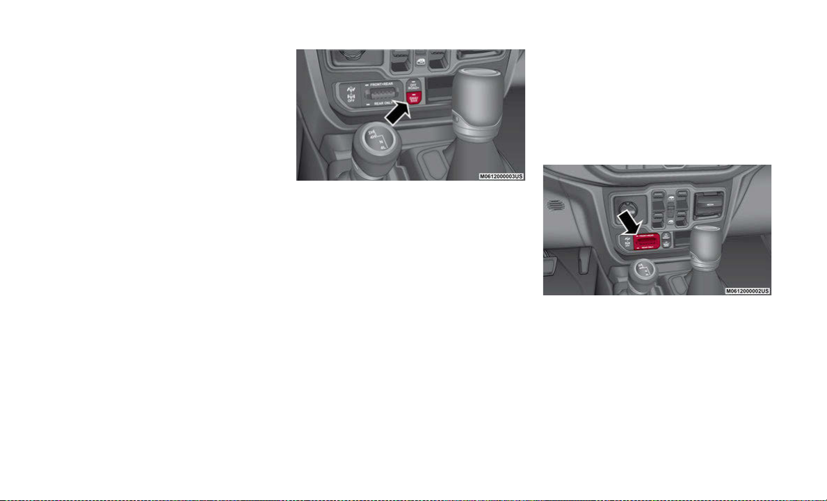
Axle Lock (Tru-Lok) — Rubicon Models
The AXLE LOCK switch is located on the
instrument panel (to the right of the steering
column).
Axle Lock Switch
This feature will only activate when the
following conditions are met:
• Ignition in RUN position, vehicle in 4L
(Low) range.
• Vehicle speed should be 10 mph (16 km/h)
or le ss.
• Both right and left wheels on axle are at
the same speed.

To activate the system, push the AXLE LOCK
switch down to lock the rear axle only (the
“REAR ONLY” will illuminate), push the
switch up to lock the front axle and rear axle
(the “FRONT + REAR” will illuminate). When
the rear axle is locked, pushing the bottom of
switch again will lock or unlock the front axle.
NOTE:
The indicator lights will flash until the axles
are fully locked or unlocked.
To unlock the axles, push the AXLE LOCK
OFF button.
The axle lock disengages at speeds above
30 mph (48 km/h), and will automatically
relock once vehicle speed is less than
10 mph (16 km/h).
ENGINE STOP/START
SYSTEM (ESS)
The Stop/Start system was developed to reduce
emissions.
NOTE:
If you press the STOP/START OFF button, the
system defaults back to on at every ignition
cycle.
Engine Stop/Start Off Button
The system will stop the engine automatically
during a vehicle stop if the required conditions
are met.
Releasing the brake pedal or pressing the accel-
erator pedal will start the engine on a vehicle
equipped with an automatic transmission.
Pressing the clutch pedal will automatically
restart the engine on a vehicle equipped with an
manual transmission.
How do I manually turn off/on the engine Stop/
Start system?
• Press the STOP/START OFF button (located
on the switch bank). The light on the button
will illuminate when the system is off.
What are possible reasons the engine does not
autos top?
• The hood is ajar.
• Driver’s door is open.
• Driver’s seat belt is unbuckled.
• The transmission is not in a forward gear.
• The vehicle is in 4L transfer case position (if
equipped).
• The vehicle has not reached a speed of
5mph (8 km/h) after the previous autostop.
• Outside temperature is too cold or too hot for
the system to operate.
• Engine has not reached normal operating
temperature.
• Cabin heating or cooling is in process and an
acceptable cabin temperature or setting has
not been achieved.
• Many of these reasons are displayed as a
Stop/Start message in the instrument cluster
display within the Stop/Start section. The
system must be in the “STOP/ START
READY” state to autostop. To access the
Stop/Start section of the instrument cluster
display, use the display controls.
How do I know I am in an autostop?
• The engine will shut down, the tachometer
will move to the zero position and the Stop/
Start telltale will illuminate in the instru-
ment cluster.
How do I start the engine while in an autostop?
• While in a forward gear, the engine will start
when the brake pedal or clutch is released or
the throttle pedal is depressed.
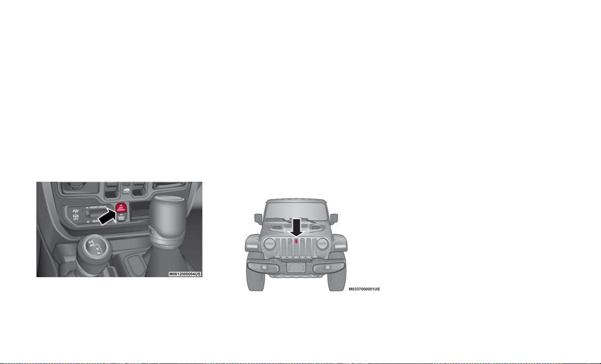
OFF ROAD+ BUTTON
Off Road+ Button
This feature allows the customer to clearly
communicate to the vehicle and the terrain it
will be operating on. The vehicle will automati-
cally adjust the operating parameters of key
systems (Throttle, Selec-Speed Control, Trac-
tion Control, Transmission Shift Mode) for
optim al performance on that terrain. The Off
Road+ button is a single button with two
distinct missions:
• If enabled in 4H, it will adjust the operation
of the vehicle for higher speeds and perfor-
mance.
• If enabled in 4L, it will adjust the operation
of the vehicle for very low speed rock picking
maneuvers.
TRAILCAM SYSTEM
TrailCam Location
Your vehicle may be equipped with the
TrailCam System that allows you to you see
an on-screen image of the terrain in front of
the vehicle. The image will be displayed on
the touchscreen display along with a caution
note “Check Entire Surroundings” across the
top of the screen.
The TrailCam view will be displayed in any
forward gear, and NEUTRAL, as long as the
vehicle speed is below 8 mph (13 km/h).
When the vehicle speed is above this range,
a timer is started and will deactivate the
camera view after ten seconds.
NOTE:
The TrailCam System will stay active while
the vehicle is in 4L (Four-Wheel Drive Low
Range).
TRAILER HITCH ZOOM
If equipped, the Trailer Hitch Zoom feature
aids the driver in lining up the vehicle’s
trailer hitch to a trailer.
While the vehicle is in REVERSE, and the
back up camera is active, the operator can
zoom in the camera’s display screen by 4x
the original view. This is done by selecting
the “magnifying glass” icon in the corner of
the display screen. To exit this view, select
the icon a second time, or place the vehicle
in a gear other than REVERSE.

TOWING
NOTE:
The trailer tongue weight must be considered as part of the combined weight of occupants and cargo (ie. the GVWR), and the GVWR should
never exceed the weight referenced on the Tire and Loading Information placard.
PHONE PAIRING
PAIRING PROCEDURE
Make sure the ignition is in the ACC or ON posi-
tion.
1. Press either the Phone button or the Settings
button in the Menu Bar on the touchscreen.
2. From the Settings list, select Phone/Blue-
tooth®, and then select Paired Phones or
Audio Devices.
NOTE:
A message will display asking, “No Phone
Conne cted. Would you like to pair a phone?”
Select Yes. After pressing Yes, the radio prompts
will take you through the steps to connect your
phone via Bluetooth®. Uconnect Phone will
display an “In progress” screen while the system
is connecting. Once the pairing has been
successful, a message will display “Bluetooth®
pairing successful: The device supports Phone
and Audio”. Click the OK button.
3. From the Paired Phone button, the Add
Device option will be listed under the “Paired
Phones” section.
Phone Pairing
Engine
GCWR (Gross
Combined Wt. Rating) Frontal Area
Max. GTW (Gross
Trailer Wt.) Max. Trailer Tongue Wt. (See Note)
3.6L 9,100 lbs (4,128 kg) 30 ft2(2.79 m2)4,000 lbs (1,814 kg) 400 lbs (181 kg)
3.6L With Max Tow 12,800 lbs (5,806 kg) 30 ft2(2.79 m2)7,650 lbs (3,470 kg) 765 lbs (347 kg)
Refer to local laws for maximum trailer towing speeds.
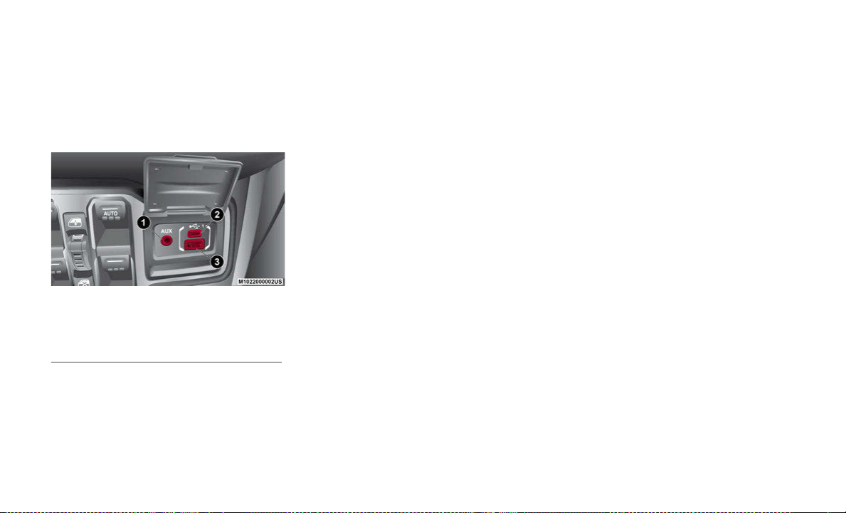
FRONT USB PORT/AUDIO
JACK (AUX) PORT
USB PORT
USB/AUX Ports
This feature allows an iPod® or external USB
device to be plugged into the USB port. The
USB port supports certain iPod® and
iPhone® devices. The USB port also
supports playing music from external USB
devices. Some iPod® software versions may
not fully support the USB port features.
Please visit Apple’s® website for iPod® soft-
ware updates. Using a USB cable connected
to the USB port, connect your iPod® or
compatible device. USB memory sticks with
audio files can also be used. The device’s
audio can be played on the vehicle’s sound
system while providing the artist, track title,
and album information on the radio display
(if available on device). When connected, the
iPod®/USB device can be controlled using
the radio or steering wheel audio controls to
play, skip to the next or previous track,
browse, and list the contents.
USB Connection
NOTE:
• The Type C USB port is the primary media
port for the radio. Two devices can be
plugged in at the same time, and both
ports provide charging capabilities. Only
one port can transfer data to the head unit
at a time.
• Both ports share a single data connection.
However, the user cannot switch between
Type A or Type C.
If a device is plugged into the Type A USB
port, and another device is plugged into the
Type C port, connection to the Type A port
will be lost. Alternatively, if a device is
plugged into the Type C port and another
device is plugged into the Type A port, the
Type C device maintains primary connection.
AUX/AUDIO JACK
The AUX/Audio jack connects a portable
audio device, such as an MP3 player, to the
vehicle’s sound system. This requires the use
of a 3.5 mm stereo audio patch cable. AUX
mode is entered by pushing the Media
button. Once in Media mode, select the AUX
button when the audio jack is connected.
Volume on the connected device may need to
be adjusted to optimize audio quality.
JEEP VEHICLE OWNERS
MOBILE APP
NOTE:
The Owner’s Mobile App content is appli-
cable to vehicles sold in the U.S. market and
are not available from the Canadian App
Store® or Google Play Store.
1 — AUX Port
2 — Type C USB Port
3 — Type A USB Port

KEY FEATURES
• Owner Information For Your Vehicle
• Accident Assistant
• Online Service Scheduling
• Roadside Assistance
• Maintenance History
• And More
To get this FREE application, go directly to
the App Store® or Google Play Store and
enter the search keyword “Jeep”.
The Jeep Vehicle Owner’s Information Appli-
cation is the essential app for owners of Jeep
brand vehicles. The app puts driver and life-
style information right in the palm of your
hand, anywhere you go. Whether it’s
providing information about specific product
features, taking a tour through your vehicle’s
equipment, staying up to date on your
vehicle’s health, knowing what steps to take
following an accident, or scheduling your
next appointment, we know you’ll find the
app an important extension of your Jeep
vehicle. Simply download the FREE app,
select your make and model, and enjoy the
ride.
FEATURES/BENEFITS
• Available for free on iOS and Android™
smartphones and tablets.
• Select Jeep brand vehicles from model
year 2011 to current model year.
• You can also add other Chrysler, Dodge,
Ram, FIAT, or Alfa Romeo vehicles.*
• Easy access to vehicle information
anywhere you go using categories, book-
marks, search, and an A-Z index.
• Vehicle information such as operating
instructions, maintenance, service history,
vehicle controls, and emergency proce-
dures.
• Find a dealer or an FCA-certified repair
facility.
• Easily document and email an accident
report.
• A parking reminder that allows you to drop
a pin on your location and navigate back to
your vehicle.
• Contact customer care with one click.
• Access to vehicle heritage, parts, accesso-
ries, and social media networks.
• Schedule your next service appointment.
• Available in English and Spanish.
*App supports selected vehicles from model
year 2011 to present.
To get this FREE application, go directly to
the App Store® or Google Play Store and
enter the search keyword “Jeep”.
AUTOMATIC CLIMATE
CONTROLS
AUTOMATIC CLIMATE
CONTROLS OVERVIEW
The Climate Control System allows you to
regulate the temperature, air flow, and direc-
tion of air circulating throughout the vehicle.
The controls are located on the touchscreen
and on the instrument panel below the radio.

Automatic Temperature Control (ATC) — If
Equipped
1. Push the AUTO button on the faceplate,
or the AUTO button on the touchscreen
while the Climate Controls screen is
displayed.
2. Next, adjust the temperature that you
would like the system to maintain by
adjusting the driver and passenger
temperature control buttons. Once the
desired temperature is displayed, the
system will achieve and automatically
maintain that comfort level.
3. When the system is set up for your
comfort level, it is not necessary to
change the settings. You will experience
the greatest efficiency by simply allowing
the system to function automatically.
Manual Operation Override
This system offers a full complement of
manual override features. The AUTO symbol
in the front ATC display will be turned off
when the system is being used in the manual
mode.
OFF ROAD PAGES — IF
EQUIPPED
OFF ROAD PAGES
Your vehicle is equipped with Off Road
Pages, which provides the vehicle status
while operating on off road conditions. It
supplies information relating to the vehicle
ride height, the status of the transfer case,
and the pitch and roll of the vehicle (if
equipped).
To access Off Road Pages, press the “Apps”
button on the touchscreen, and then select
“Off Road Pages”.
Main Menu
OFF ROAD PAGES STATUS
BAR
The Off Road Pages Status Bar is located
along the bottom of Off Road Pages and is
present in each of the three selectable page
options. It provides continually updating
information for the following items:
• Current Transfer Case Status
• Current Latitude/Longitude
1 — Off Road Pages App
2 — Uconnect Apps Button

• Current Altitude of the vehicle
• Status of Selec-Speed Control and
Selected Speed in MPH (km/h)
DRIVETRAIN
The Drivetrain page displays information
concerning the vehicle’s drivetrain.
The following information is displayed:
• Steering angle in degrees
• Status of Transfer Case
• Status of the Rear Axles — If Equipped
PITCH AND ROLL
The Pitch And Roll page displays the
vehicle’s current pitch (angle up and down)
and roll (angle side to side) in degrees.The
pitch and roll gauge provide a visualization of
the current vehicle angle.
ACCESSORY GAUGE
The Accessory Gauge page displays the
current status of the vehicle’s Coolant
Temperature, Oil Temperature, Oil Pressure,
Transmission Temperature, and Battery
Voltage.
TRUCK BED
POWER INVERTER
There is a 115 V (400 W) exterior power
inverter located on the right rear side of the
truck bed near the tailgate. This inverter can
be turned on by the Instrument Panel Power
Inverter switch located to the left of the
steering wheel. This inverter can power
cellular phones, electronics, and other low
power devices requiring power up to 400 W.
Certain high-end video game consoles
exceed this limit, as will most power tools.
Exterior Truck Bed Power Inverter
NOTE:
• 400 W is the maximum for the inverter,
not each outlet.
• If two outlets are in use, 400 W is shared
amongst the devices plugged in.
• The Power Inverter will only turn on if the
ignition is in the ACC or ON/RUN position.
• Due to built-in overload protection, the
Power Inverter will turn off if the power
rating is exceeded.
BED LIGHTS — IF EQUIPPED
The bed lights (if equipped) are turned on by
pushing the bed light switch located on the
lower half of the headlight switch.
Bed Light Switch
A telltale will illuminate in the instrument
cluster display when these lights are on.
Pushing the switch a second time will turn
the lights off.
The bed lights will turn on for approximately
60 seconds when a key fob unlock button is
pushed, as part of the Illuminated Entry
feature.
TAILGATE
THREE-POSITION
TAILGATE
The vehicle’s tailgate can be set to three
positions: open, mid, or closed. The tailgate
is dampened to provide a slower, more
controlled lowering.
To use the mid position, open the tailgate
and lower it to near mid position. Secure the
tailgate in this position by looping the tail-
gate straps behind the circular retainer on
the box sides.
Tailgate In Mid Position
NOTE:
Three 2x4 boards are needed to provide
support at the two forward locations when
hauling cargo using the mid position and the
tailgate.
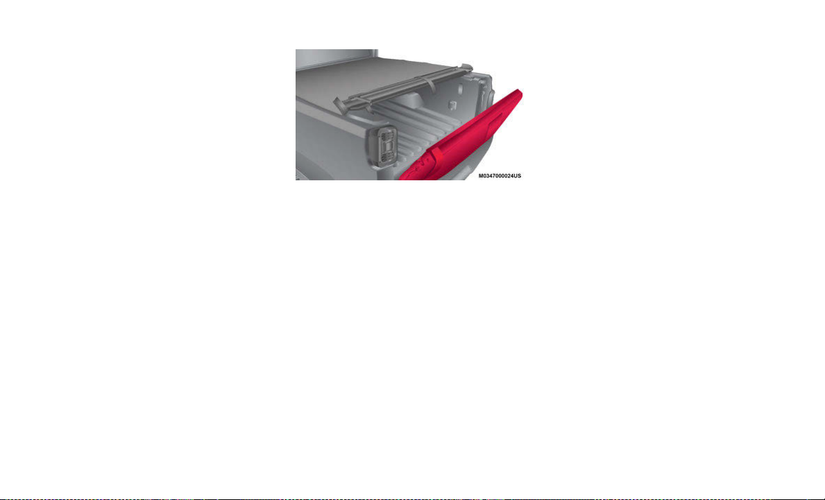
TONNEAU COVER
REMOVING THE TONNEAU
COVER
To remove the Tonneau Cover, proceed as
follows:
1. Open the tailgate to access the red
Tonneau Cover release straps, and pull
either one to disengage the locking
mechanism.
2. Roll the Tonneau Cover forward, starting
with the rear bar and continue to roll
toward the front of the truck bed.
3. Using the stowage straps, secure the
Tonneau Cover in the rolled up position.
4. Using a #T50 Torx head driver, remove
the two fasteners securing the Tonneau
Cover to the front of the truck bed.
5. Utilizing two people, lift the Tonneau
Cover up and away from the truck bed.
INSTALLING THE TONNEAU
COVER
To Install the Tonneau Cover, proceed as
follows:
1. Position the rolled up Tonneau Cover on
the truck bed and align it to the two
fastener locations at the front of the bed.
2. Using a #T50 Torx head driver, secure
the fasteners to the bed.

3. Lower the tailgate to the fully open posi-
tion and release the stowage straps used
to secure the Tonneau Cover in the rolled
up position.
4. Roll the Tonneau Cover rearward toward
the back of the truck bed.
5. Position both Tonneau Cover latches over
the locking mechanisms (one on each
side of the truck bed), making sure the
plastic retainer is correctly seated in the
forward part of the latch, then push down
firmly on the rear center of the cover to
engage the locking mechanism.
BED RAILS
BED RAIL TIE DOWN
SYSTEM
There are two adjustable utility rail cleats on
each side of the bed that can be used to
assist in securing cargo inside the vehicle’s
truck bed.
Adjustable Cleats
Each utility rail cleat must be tightened
down in one of the detents along either utility
rail in order to keep cargo properly secured.
To move the cleat to any position on the rail:
1. Turn the cleat retainer nut counterclock-
wise, approximately three turns.
2. Pull out on the cleat.
3. Slide it to the nearest detent of the
desired location.
4. Tighten the nut.
NOTE:
Make sure the cleat is seated in the detent
before tightening the nut.
SAFETY
SELEC - SPEED CONTROL
(SSC) — IF EQUIPPED
Selec - Speed Control (SSC) is intended for
off road driving in 4L Range only. SSC main-
tains vehicle speed by actively controlling
engine torque and brakes. This allows the
driver to focus on steering the vehicle in
off-road situations.
SELECTABLE TIRE FILL
ALERT — IF EQUIPPED
The Selectable Tire Fill Alert (STFA) system
is an optional feature that is included as part
of the normal Tire Fill Alert system. The
system is designed to allow you to select a
pressure to inflate or deflate the vehicle's
front and rear axle tires to, and to provide
feedback while inflating or deflating the
vehicle's tires.
The system will be activated when the TPM
receiver module detects a change in tire
pressure. The ignition must be in the ON/
RUN mode, with the transmission in PARK
in vehicles with an automatic transmission,
and in NEUTRAL with the parking brake
engaged in vehicles with a manual transmis-
sion. The hazard lamps will come on to
confirm the vehicle is in Tire Fill Alert mode.
JEEP® WIRELESS
SPEAKER — IF
EQUIPPED
WIRELESS SPEAKER
Your vehicle may be equipped with a wireless
Bluetooth® speaker. The speaker is located
on the rear passenger side of the vehicle. To
access the speaker, pull the seat back
release strap, pull up on the tether on the
speaker dock, and the speaker will be
released. To reinstall the wireless speaker,
place the speaker in the dock and push it
back to lock into place.
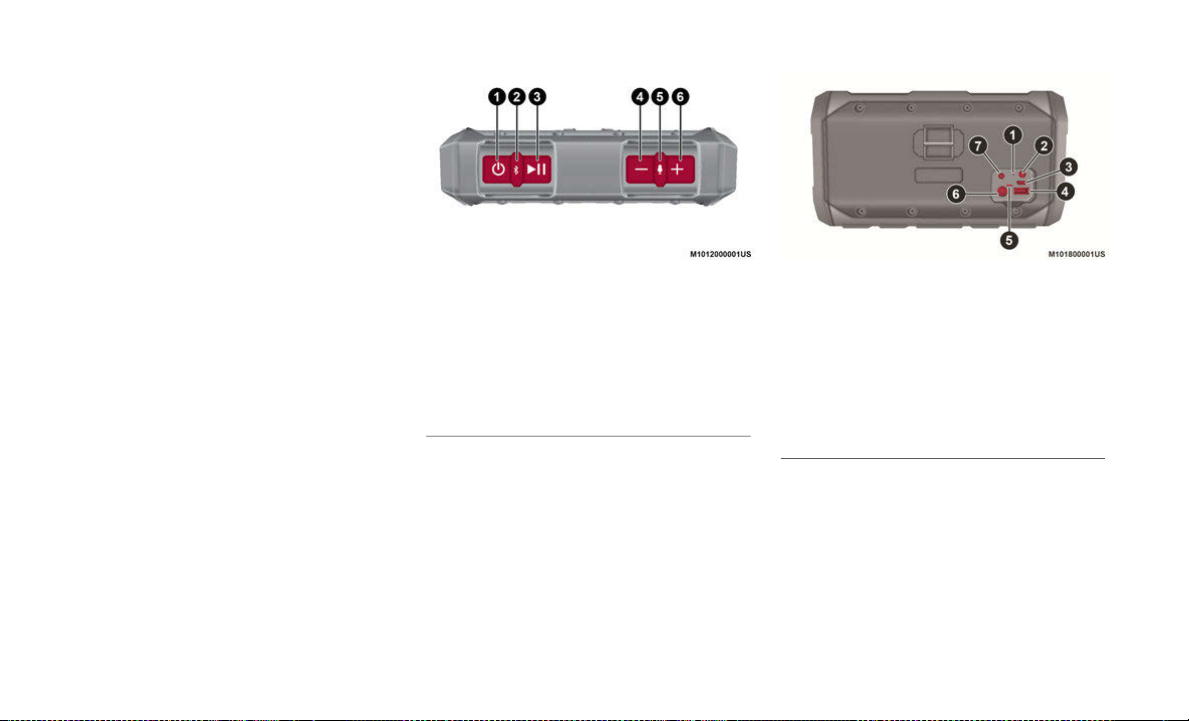
Speaker Buttons Rear Speaker Outlets
The Bluetooth® word mark and logos are
registered trademarks owned by Bluetooth
SIG, Inc. and any use of such marks by FCA
US LLC is under license. Other trademarks
and trade names are those of their respective
owners.
1 — Power ON/OFF
2 — Bluetooth®/App Pairing
3 — Play/Pause
4 — Volume Down/Skip Back
5 — Voice Control/Call Control
6 — Volume Up/Skip Forward
1 — Reset Button
2 — Battery Status Button
3 — Service/Diagnostic
4 — Type A USB Charging Port
5 — Battery Status LED
6 — Speaker Charging Port
7 — Aux Port

SIRIUSXM GUARDIAN™
— IF EQUIPPED
ACTIVATION
To use SiriusXM Guardian™ emergency,
remote and security services, you must acti-
vate your SiriusXM Guardian™ account.
1. Press the Apps icon on the bottom of your
in-vehicle touchscreen.
2. Select the Activate Services icon from
your list of apps.
3. Select the Customer Care button to speak
with a SiriusXM Guardian™ Customer
Care agent who will activate services in
your vehicle, or select the Enter Email
button to activate on the web.
Once you have activated your services, you’re
only a few steps away from using remote
services.
SiriusXM Guardian™
To use SiriusXM Guardian™ remote services,
download the Uconnect Mobile app:
• Once downloaded, use your Owner
Account login and password to open the
app.
• Include similar language: You will use your
SiriusXM Guardian™ PIN to execute these
remote services.
• Press the Location button on the bottom
menu bar of the app to bring up a map to
locate your vehicle or send a location to
your Uconnect Navigation (if equipped).
• Press the Settings menu in the upper left
corner of the app to bring up app settings
and access the Assist Call Centers.
For further information:
• U.S. residents visit: siriusxm.com/
guardian
• Canadian residents visit: siriusxm.ca/
guardian/
FEATURES
SiriusXM Guardian™ keeps you connected to
your vehicle. You have access to safety,
remote, and security services.
In-Vehicle Features
SiriusXM Guardian™ enhances your owner-
ship and driving experience by connecting
your vehicle to an operable network. When
connected to an operable network, you have
access to:
• SOS Call: Connect to a live agent who
contact emergency services and stays on
the line with you until help arrives.
• Customer Care Assistance: Speak with a
live agent when you push the ASSIST
button on your rearview mirror to get Road-
side Assistance or support.
Table of contents
Other FCA US Automobile manuals


