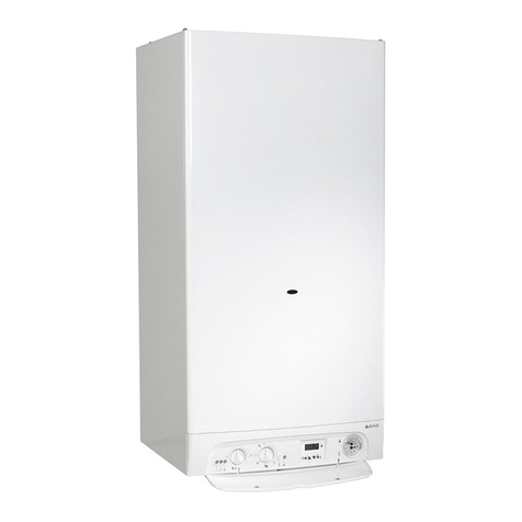
FEG C 24 H User manual

USER’S MANUAL
Wall-mounted boiler for central heating
C 24 H
Fűtéstechnikai Készülékgyártó Ltd.
Hungary, 6900 Makó, Aradi street 136.

1
CONTENTS
Welcome among the customers of our products! ................................................. 2
Major particulars for the sake of your safety and peace....................................... 2
1.Technical parameters and dimensions................................................................ 2
1. STRUCTURAL DRAWING...................................................................................................... 3
1.2 HYDRAULIC SCHEME OF CH WALL-MOUNTED BOILERS................................................... 4
1.3 TECHNICAL DATA.............................................................................................................. 5
2. General instructions for installation ................................................................... 5
2.1. PLACEMENT OF THE APPLIANCE ..................................................................................... 5
2.2 MOUNTING THE APPLIANCE.............................................................................................. 5
2.3. AIRING OF ROOMS........................................................................................................... 6
2.4. FLUE GAS PIPING............................................................................................................. 7
2.5. FILLING AND PUTTING INTO OPERATION.......................................................................... 8
2.6. ELECTRIC DESCRIPTION.................................................................................................. 8
2. 7CONNECTING OF ROOM THERMOSTAT:........................................................................... 9
2.8. INSTALLATION................................................................................................................ 10
2.9. FROST PROTECTION:.................................................................................................... 11
2.10. FIRST INSTALLATION ................................................................................................... 12
2.11. INSTALLATION AND SHUT DOWN ................................................................................. 13
2.12. ADJUSTMENT OF BURNER PRESSURE ........................................................................ 13
2.13. ADJUSTMENT FOR ANOTHER TYPE OF GAS ................................................................ 13
2.13. ADJUSTMENT FOR ANOTHER TYPE OF GAS ................................................................ 14
2.14. RULES OF REPARATION AND MAINTENANCE............................................................... 14
3. Instructions for use and maintenance for users.............................................. 15
3.1. IGNITION ........................................................................................................................ 15
3.2. OPERATING ................................................................................................................... 15
3.3. ADVICE FOR ECONOMICAL OPERATING......................................................................... 15
3.4. SHUT-DOWN.................................................................................................................. 16
3.5. INSTRUCTIONS FOR MAINTENANCE............................................................................... 16

2
Welcome among the customers of our products!
We hope that our new type, economic, reliable water heater, which requires little room will satisfy
you in all respects. To have an undisturbed operation, long durability and economical running please
study the Instructions for Use thoroughly.
The heating appliances are adjusted to the desired type of gas. The devices equipped with a
room thermostat or with another switching type controller (e. g.: with a timer) work fully automatically.
The appliances can be used either for opened or closed loop heating systems. For a closed loop
heating system the suitable fittings- a closed expansion tank, a safety valve, a pressure gauge are
needed. Although the appliance is not suitable for direct connection to floor heating systems,
appropriate auxiliary fittings allow this application.
The boilers can be deployed altogether with a water heater. If the regulations for the chimney
or for the air space make it required, a blocking system must be used.
Major particulars for the sake of your safety and peace
Boilers can only be operated by a person who has learnt their operation, knows the fire safety
regulations and is not disabled.
If the regulations laid down in the Instructions for Use are not met, the operator of the appliances is
liable for all the ensuing consequences. It is PROHIBITED to take hot water directly out of the boiler or
out of the heating system!
If the operator notices that the pilot extinguishes on its own (e.g. as a result of gas cut-off),
switch it on after about a minute, if it extinguishes again or you notice any kind of disorder (e.g. gas
leakage, excessive smoke, unpleasant smell, etc.) put the appliance out of action. Turn off the gas tap
under the appliance and cut off the current.
In case of a gas leakage turn off the gas valve under the appliance, air the room (meanwhile
do not switch on any electric appliance, do not move any electric wall plug, do not employ an open
fire). In case of further gas leakage turn off the main gas valve under the gas meter. The gas leakage
must be reported to the local gas company.
Disorders can only be fixed by a skilled serviceman. The appliance MUST NOT be used until
the disorder is fixed!
In case of failure of the appliance, skilled repairmen of gas appliance services must be
contacted (addresses of service networks is enclosed). For housekeeping purposes in the room where
the boiler is mounted, only one - in a flat maximum two-either 11,5 kg or 23 kg loading weight gas
cylinders can be stored with a total loading weight not more than 35 kg.
Flammable materials cannot be kept under and nearer than 60cm beside the appliance. The
instructions for use must be preserved and kept in a place where it is available for the operator. If it
gets lost it must be substituted.
1.Technical parameters and dimensions
The C24H boilers are equipped with an atmospheric injector burner, a water circulating pump, a
thermoelectric flame safety device, a manually ignited pilot burner and a flue-gas connection to be
joined to a chimney having natural air flow. The appliances can be used for opened and closed loop
heating systems as well.
Control unit: ELEKTRONIKA MECHANIKA CH-12-40
Water temperature control: T7335 HONEYWELL NTC thermistor
Safety water temperature limiter, flue-gas backflow sensor: 2pcs. of EMERSON 36TXE-12732
Accelerating pump: WILO EARS 20/70
Combined gas valve: HONEYWELL V4600 1367-230V-50Hz
The boilers contain all the safety and control units that are specified by the regulations.
Subassemblies:
•Brass heat exchanger with oval tubes and bossed lamellas.
•Two-point control in accordance with the temperature of the room and of the heating water.
The temperature of the delivered water and the maximum temperature are displayed
electronically.
•Flue-gas backflow sensor wired into the circle of thermoelectric flame safety device, water
temperature monitoring safety limiter thermostat.
•Double insulated casing

3
DIMENSIONS
1. Structural drawing
Delivery pipe
1
2
3
4
5
6
7
8
9
10
11
13
14
15
16
17
18
Deflector
Heat exchanger
Boiler shell
Gas valve
Case
Burner
Pilot flame holder
Flue-gas backflow
sensor
Limiter thermostat
Pump
Electric control box
Purging screw
Thermocouple
Gas inlet pipe
19
20
Thermistor
Display
A
G
B
Delivery water
Gas connection
Returning pipe
1
3
4
5
6
7
2
8
9
10
11
12
13
14
15
A G B
12
Temperature knob
16
Return heating pipe
17
18
Back sheet
19
20
Fig. 2.
430
800 10
275
138
15
Fig. 1.

4
1.2 Hydraulic scheme of CH wall-mounted boilers
230 V, 50 Hz
A G B
1
2
3
4
5
6
7
9
10
1
ADelivery pipe
BReturning pipe
GGas connection
Electric control box
2Gas inlet
3Thermocouple
4Burner
5Heat exchanger
6Delivery temperature
sensor NTC
7
8Flue-gas backflow sensor
Limiter thermostat
9Deflector
10 Purging screw
11
11
Pilot flame pipe
12
12 Magnetic valve
13 Gas valve
14
15
15
Pump
16
16 Expansion pipe
17
17 Mains connection
18
18 Room temperature controller
19
19 Charging-discharging valve
13
14 Display
Fig. 3.
8

5
1.3 Technical data
Trademark: C24H
Manufacturer: Novum-Fég Fűtéstechnikai és készülékgyártó Kft.
Type: B11BS
Type of gas: II2HS3B/P
Allowed maximum operating pressure: 3 bars
Allowed maximum heating water temperature: 90 ºC
T
yp
e of
g
as: „H” natural
g
as „S” natural
g
as Pro
p
ane
g
as
Joint gas pressure: 25 mbar 25 mbar 30 mbar
Ø of burner nozzles (mm) 1,18 1,28 0,68
Ø of pilot burner: 0,3 0,3 0,2
Nominal heating capacity (kW): 24 18.3 24
Nominal heating load (Kw): 27,3 21,1 27,3
Adjustable min. heating load
(kW): 13,8 10,6 ---
Burner pressure at max.
capacity: 11 mbar 9 mbar 29 mbar
Burner pressure at min.
capacity: 2,8 mbar 2.3 mbar ---
Nominal gas consumption
max/min *: 2,89-1,46 2,46-1.23 0,85
Efficiency (%): 88 86,7 88
Pcs. of main burner nozzles: 16 16 16
Flue
g
as connection: Ø
132 mm
Ad
j
ustment ran
g
e of water 50 - 90 °C
Electric
p
ower: 230 V
,
50 Hz
Fuse
(
mA
)
: 800
;
100
Max. electric
p
ower Max. 130 W
Protection: IP 45
Shock
p
revention cate
g
or
y
: I.
Adjustment range of room
temperature controller: 5-30 °C
Wei
g
ht
(
k
g)
: 22
(*): At 15 ºC and 1013 mbar
Table 1.
2. General instructions for installation
2.1. Placement of the appliance
-Make sure that the wall is suitable for mounting the appliance on it.
-Avoid mounting on less solid separation walls.
-Do not mount the boiler above an appliance that could influence the perfect operation
of it. (E.g.: kitchen appliances generating greasy steam.)
Do not install the boiler in a room where the air is corrosive or dusty.
2.2 Mounting the appliance
Before setting to mount the boiler the whole heating system must be flushed as much as possible
in order to remove stains out of the tubes and radiators, which by getting into the appliance alter its
operation (especially sludge, metal parts, oil and grease). Before connecting the boiler to an "old", big
water-spaced system it is important to flush the circle, to remove the scale by solution of acid and to
install a filter into the returning pipe in front of the boiler.
With the help of a suitable designer a technical plan must be made about the heating system, the
gas supply, the flue-gas piping and the electric connections.

6
1. Insert plugs into the wall at the distances and heights shown in Figure 4.
2. Drive in the screws.
3. Hang the appliance on the screws through the openings of the back sheet.
Water connections
The delivery and return pipes must be equipped with closing fittings. This allows fast and simple
separation of the boiler without changing the heating water in the system.
The connection of the expansion tube is to be mounted into the return pipe.
Mounting a closing fitting between the expansion tube and the boiler is prohibited.
NOVUM-FÉG Ltd. Co. is not liable for damages caused by neglecting these technical warnings.
Hydraulic characteristic curve of pump (Fig. 1. C-24H)
The hydraulic characteristic curve of pump helps to design the heating system. During calculating
the pressure drop caused by radiators, temperature control valves, radiator throttles, water filter
and pipes of system must be taken into account.
Gas connections
The cross-section of the connecting pipe must be at least the same or bigger than of the gas pipe
in the boiler. A closing fitting must be mounted before the appliance. The furnace can be joined
the gas system by a skilled and licensed serviceman.
Before installation, i.e. joining the gas-meter, carefully check the compactness.
During installation the following procedures have to be made:
-Allow air out of the tubes.
-Check the gas-leakage of the closing fittings. After half an hour of starting probe the manometer
must not show pressure drop. The accidental leakages can be detected by soap suds and have to
be eliminated immediately.
2.3. Airing of rooms
The boiler has to be installed in a room appropriate for the actual rules.
Direct and indirect ventilation (according to Hungarian standard):
-Maximum specific load of the room can be 3140 W/m³ (basic air space).
1032
0
1
2
3
4
5
6
0100 200 300 400 500 600 700 800 900 1000 1100 1200
Capacity, Q (l/h)
II.
I.
III.
1300 1400
M
∆
T=25K
∆
T=15K
Total Head, H (m)
C-24H
250
O6
O132
229
563
15
571
800
G3/4 G 3/4
G 1/2
275
75
Fig. 4.
0.4-1.4 m
138
121 121
430

7
-Between 1750-3140 W/m³ specific load the room must be ventilated to another room by 2 pcs. of
non-lockable vents. The cross section of these must be at least 1510 cm² and there must be a
minimum of 1,8 m vertical distance between them. In this case the next parameters have to be
realized:
-total specific load must be under than 1250W/m³.
-total cross section (of door or window) opening to open air or staircase must be 1,3m².
-a card prohibiting covering of vents is to be placed in the room. Under 1750W/m³ specific load
there is no need for airing if the room has a door opening to open air or a window bigger than
1,3 m² or the door opens to a room having this kind of window. Otherwise ventilation is to be
realized according to points a) and b). (The shut-off device must not be leakproof).
With the exception of bedroom and rooms for constant stay the appliance can be installed in
any kind of room if the following conditions are realized in case of an opened combustion
chamber:
-maximum vertical distance between the boiler and the chimney is 0,2 m.
-vertical distance of lower edge of the boiler from the floor must be 0,4-1,4 m.
-operation and repairability must be ensured. A space of 0,1 m on the sides and 0,8 m on
the front must be left.
-the boiler can only be mounted on a wall made of non-burnable materials (thickness of
wall must be a min. of 0,1 m.)
-gas equipments must not be installed above each other.
-two gas equipments (in one room) can be joined the same chimney provided the vertical
distance of their connections is min. 0,3 m and neither of the appliances exceeds 35 kW
nominal heating capacity.
-it is recommended to make between the upper edge or the deflector of the appliance a
chimney intake, which length is triple of the diameter of the chimney.
-if the boiler is placed into a cabinet, then it is to be built from floor to ceiling, its walls and
door must be made of non-burnable material. If possible, its door should be gridded.
2.4. Flue gas piping
Designing, implementing, method of connecting, dimensioning chimneys are specified by standards of
building. The appliances can be connected to a chimney permitted by the chimney-sweeping
companies. The chimney has to be gas-proof.
A boiler can be installed even in a cellar provided the room is damp-proof and has a solid floor.
-smoke tube must be resistant against mechanical effects (aluminium tube is suitable).
- smoke tube is to be resistant against temperature of flue-gas and accompanying
condensation.
-max. horizontal piping of smoke-tube is 2m.
-diameter of smoke-tube can not be smaller than the connection stub of deflector.
-cross section of quadrangular chimneys must be 10% more than the connection stub of
the appliance.
-above deflector there must be a min. of 3D long straight section. (Hungarian standard).
-material of smoke-pipe should be aluminium sold in trade.
Placement of boilers operated by PB gas
The appliance must not be placed in:
-a cellar if all of its walls and its floor are under ground level.
-a building made of panel units.
-a residential building if there is a cellar or subground floor in it.
-specific weight of PB gas is higher than of air so the general rule is that gas should not be able to set
in druses and canals because it may explode.
Attention
The boiler has got a flue-gas backflow sensor. When it starts operation the boiler stops automatically.
Restart can only be made by manual ignition of pilot flame.
Disabling, damaging and/or demounting of safety system is prohibited!
In case of repeated failures a skilled serviceman must check the chimney.
The producer is not liable for damages caused by faults of installation, incorrect use, changes
made in the appliance or neglecting manufacturer's instructions and valid regulations.

8
2.5. Filling and putting into operation
Filling must be carried out by soft water. Before starting filling every valve must be opened and the
outlet valves must be closed. Air discharging valves are to be opened and ensure that the caps of
automatic ones' are opened to 1-2 turns.
Filling must be done slowly. Keep an eye on lower situated purging points and purging valves of
radiators and close them after the appearance of water. Automatic purgers' caps must not be closed!
Purging of pump can be done by unbolting the screw on the front of it. Purging of boiler can be done
during slow filling by air discharging valve situated on heat exchanger.
Technicalness is very important from the point of long operation life. Frequent charging or discharging
of the system or certain parts of it and other water losses (leakages) cause consequential refill. This
means letting corrosion causing oxygen into the system. If water quality is not suitable than scaling
occurs.
It is recommended to carry out first heating-up slowly (approx. in 5 hours) in the interest of scaling
reduction and perfect purging.
First month purge the system in warm status during continuous refill to let aggregated air out
of the pipes.
2.6. Electric description
(This chapter describes information only about the electric part of boiler. It does not contain hydraulic,
gas technical and installation tasks connecting to the operation of electric unit!)
Preparations for installation
For operation of the appliance the supply voltage is 230V 50Hz. The boiler has a 2m long connection
cable. The user has to provide a two-pole earthed wall-socket placed beside the appliance-or in case
of a bathroom in zone 3-and connect it to the electric network of the house. Max. current drain of the
boiler is not bigger than 1Amper.
Attention!
The user has to arrange mounting, connecting, shock-hazard protection and fire prevention inspection
of the wall plug.
The user also has to provide a room thermostat and its mounting to the suitable place from heating
technical and control engineering point of view as well as a connection cable pulled out from the boiler
to the room thermostat. For a connection cable the most appropriate one is a three-conductor cable
with a nominal voltage of min. 0,4 kV and with a cross-section of 1mm² for each wire. Pull this cable to
the room thermostat without interruption.
The controlling electronics located behind the boiler casing are mounted in a sealed plastic box. Their
protection ratio is IP 44. In case of boilers where the casing cannot be opened (but the case can be
taken off) the protection ratio of the (whole) appliance is IP 45, so if it mounted in a bathroom it can be
placed to zone 1. (According to Hungarian Standard).
After removing boiler casing and cover of controlling box the wiring points can be reached.
Attention!
After removing the cover of control box the points conducting mains voltage (230 V) can be touched!
Therefore:
(1) Removal of cover and connecting (e.g.: the room thermostat) from the box is allowed only in no-
voltage state: the mains plug must be pulled out of the wall-socket.
(2) Adjusting in a voltage state of trimmer potentiometer located in electronic panel must be done by
an insulated screwdriver.
(3) Steps described in points (1) and (2) can be carried out by an electrician!
Items in the control box wired up by factory (see Fig. 5.):
-pump
-gas magnetic valve
-DWT potentiometer

9
-DWT thermistor
-display
Jumper can be found:
-between points 8 and 9
-and 10 and 11
2. 7 Connecting of room thermostat:
For operation of the boiler the room thermostat must be connected.
-Remove jumper between points 8 and 9.
-Wire up to points 8 and 9 the heating operating contacts of room thermostat.
If proper operation of room thermostat needs mains voltage 230V than from point 7 the neutral
conductor must be connected to the room thermostat. (At point 8 mains phase is located and at point
9 phase must appear only in case of request for heating).
Notes: (1) In relation to conductors phase and neutral see notes (*) under Table 1.
(2) Short circuit caused by false connecting of room thermostat results in blowing of 100mA
fuse marked F2. After proper connecting and change of fuse the circuit will be ready to operate.
-Optionally connectable:
a) Lock (e.g.: switch clock, timer, chimney damper, water heater lock, etc.) between points 10 and 11.
For this first remove the jumper.
b) For an appliance with low current input (e.g.: Floor heating module, electronic temperature
controller, etc.) mains input can be connected from points 5 and 6 (which inputs stop when the mains
plug of boiler is disconnected).
Table 1.
Sign Number Sign Name Description
1 Lsz Controlled phase* (out)
2 N Pump Neutral* (out)
3 L Phase* (in)
4 N 230 V in Neutral* (in)
5 L Phase* (out)
J1
6 N 230 V out Neutral* (out)
7 N Neutral* (out)
8 Lth Phase with fuse* (out)
9 Lk
Room thermostat
Phase with fuse, switched* (in)
10 Lk Phase with fuse, switched* (out)
J3
11 Lr Lock Phase with fuse, switched and lock* (in)
12 Lg Controlled phase* (out)
J2 13 N
Gas Magnetic Valve Neutral* (out)
14 GND Base connection (out)
15 +VAR Variable resistance (out)
16 +C ON
DWT**
Potentiometer Permanent resistance (in)
17 GND Base connection (out)
J4
18 +VAR DWT**
Thermistor Variable resistance (in)
19 +5 V +5 V (out)
20 SCL SCL (out)
21 SDA SDA (out)
J5
22 GND
Display
Base connection (out)
Notes for Table 1.:
Protection conductors are connected to the shock hazard protection bus wire!
* Names "Phase" (L) and Neutral (N) are only given to make points defined at the same voltage level.
Naturally phase and neutral can be changed (during input)! The electronic panel is not phase-
sensitive.
** DWT= Delivery Water Temperature

10
2.8. Installation
When preparation is carried out installation may start. Its steps are:
(3) Adjust room thermostat to a temperature lower than of ambience.
(4) Apply voltage to the appliance: plug the cable of boiler into the wall socket.
•The actual delivery water temperature appears in the display, showing range 3-91 ºC. (e.g.:
actual DWT is 58 ºC).
•The pump starts to operate and carries out a 1 minute "pre-circulation".
•The proper operation of electronics is signed by slow beat flash of yellow LED marked D9.
(5) Wait for pass of 1 minute. This 1-minute pre-circulation is carried out after each restart or
power failure. If there is not request for heating (on the part of room thermostat) the pump stops
after 1 minute.
(6) Adjust the required temperature of delivery water (required DWT (P))
Turn the knob (can be operated from outside) at the bottom of control box while checking display.
As an effect of adjustment the display changes from actual DWT (C) to required DWT (P) E.g.:
required DWT is 80 ºC.
•Two seconds after finishing adjustment the display changes back to actual DWT (C).
(1) Adjust hysteresis of switching.
Explanation for hysteresis of switching: Heating turns off at the adjusted required temperature of
delivery water previously described in point (4) and turns on at a 10-25ºC lower ongoing
temperature to be adjusted now (provided there is a request for heating on the part of room
thermostat).
•Turn potentiometer located on electronic panel and marked P1 by a screwdriver while checkig
the display. As a result of adjustment display changes from actual DWT (C) to hysteresis (H).
Hysteresis can be adjusted between 10-25 ºC (e.g.: hysteresis 15 ºC).
Two seconds after finishing adjustment the display changes to actual DWT (C).
(2) Adjust room thermostat to a requested temperature higher than the ambient temperature.
•The pump and the main burner switch on and the boiler starts heating. Whether turn on or off
happen at the adjusted DWT can be checked in the display.
•Proper operation is shown by quick beat flash of LED marked 9 located in electronic panel.
•After each turn off of heating the pump carries out a 1-minute post-circulation and stops
unless DWT meanwhile dropped under the adjusted hysteresis value (and the room
thermostat keeps on requesting for heating). In this case turn on to heating happens
immediately and pump carries out not post-circulation but normal circulation, which is
simultaneous with heating.
•In case of post-circulation LED D9 flashes in slow beat.
Notes for installation:
(1) Adjustment can only be done when there is not request for heating (on the part of room
thermostat) and the pump does not operate in mode pre- or post circulation (i.e. it does not
work), namely the boiler operates in standby mode!
(2) However adjustment of DWT potentiometer is effective during operation.
As an effect of adjustment the display changes from actual DWT (C) to required DWT (P).

11
Error signals and their correction:
If heating stops because of an error a fault sign appears in the display. From the signal the conclusion
can be drawn to the cause of error.
Error of DWT sensor (ErC)
Sign in display:
Cause of failure can be:
•DWT sensor (or its circuit) is broken.
•Matching circuit of DWT sensor is faulty
(Notes: Under 3 ºC electronic panel considers thermistor dead-shorted, inhibits operation of gas
magnetic valve while ErC sign appears in the display).
Fault of overheating (ErF)
Sign in display:
Cause of failure can be:
•DWT rose (abnormally) above 91 ºC.
•Dead short in DWT sensor (or in its circuit).
Not operating-like rise of heating water temperature (ErG)
Sign in display:
When the slope of temperature-change of DWT under 35 ºC is higher than 10 ºC/ sec. or above
35 ºC the slope of temperature-change is higher than 5 ºC/ sec. the control electronics send an
error sign without abortion of operation of main burner.
Cause of failure can be:
•Minimum required quantity of water is not provided.
•Temporary lack of water in the leaking heating system.
(Notes: Above 91 ºC the electronics consider thermistor dead-shorted and inhibits operation of
gas magnetic valve while ErG sign appears in the display).
The localization of fault need a skilled serviceman.
2.9. Frost protection:
When DWT sensor feels temperature under 5ºC the electronics switch boiler on heating even if there
is not request for heating (from the part of room thermostat). This frost protective heating operates
until 25 ºC DWT. Reaching this value the boiler stops after a 1-minute post-circulation.
Notes: frost protection starts to operate only when the gas supply of boiler is ensured, the pilot
flame is burning and the mains are provided as well.
Fuses:
The boiler controller electronics have two quick-break fuses. The main fuse (at the same time fuse of
the pump) is marked F1, its nominal current load is 800mA. Fuse marked F2 belongs to inner
electronic circuits with nominal current load of 100mA.
When change fuses apply only ones with the same parameters!

12
2.10. First installation
Preliminary inspection
Before installation make sure about the following:
-whether gas and electric assembly is in accordance with standards?
-whether flue-gas pulling system and its assembly correspond with the user's manual? Very important:
flue-gas must not get into the room.
-the system is to be filled with water.
-valves of system are to be opened.
-the applied gas must correspond to the one described in the plate of boiler, otherwise the appliance is
to be modified for operation by the supplied gas (SEE: CHAPTER "ADJUSTMENT FOR ANOTHER
TYPE OF GAS).
-gas valve must be opened.
-leakages are to be terminated.
Mains 230V IN
1
2
3
4
7
8
9
10
11
12
13
14 15 16 17 18 19 20 21 22
M
Room
thermostat
Lock
Temperature controller
potentiometer of delivery
water
Boiler
thermistor
Pump
Mains connection
~230 V / 50Hz
Magnetic valve
LOCK I.
On connecting room thermostat jumper is removed
Connecting according to user's manual
of room thermostat (8-9 switch contacts)
Connection Diagram
CH12-40 control panel
C 12H, C 18H, C 24H, C 40H
5
6
Mains out
~230 V / 50Hz
Display
White
Yel low
Green
Brown
P1 pot.meter
F1 1000 mA F
F2 100 mA F
D9
Led
Fig. 5.

13
2.11. Installation and shut down
Instructions for installation and shut down of boiler see in chapter 3. INSTRUCTIONS FOR USE AND
MAINTENANCE FOR USERS.
2.12. Adjustment of burner pressure
The next instructions are only for technicians authorized to service.
Every appliance is put into circulation in a tested and adjusted state.
The output of a heating appliance can be adjusted between values shown in Table 1.
This way the proper output supplies the system without excessive stress of boiler but keeping the high
efficiency.
Attention: operation of the appliance above or under the given values is prohibited!
In order to adjust the combined gas valve correctly follow the next steps:
- Connect a pressure gauge to stub C after loosening of closing screw. Pressure of connecting gas
can be measured on stub "E" in case of necessity (Fig. 6.).
- Remove closing screw "A".
- Operate burner.
- Adjust required burner pressure by turning of screw "B". Turning CLOCKWISE increases and
COUNTER-CLOCKWISE
- Adjust height of pilot flame by the same method using screw "D".
- Shut main burner down by turning the knob, close adjustment screw by the closing screw, remove
pressure gauge, close measuring stub by the closing screw.
- Operate the burner again by ignition of pilot flame and main burner. Check compactness by soap
sud.
- "Lead stamp" closing screw by paint.
- State adjusted data in maintenance log-book (burner pressure mm, gas load m³/ min.).
A
BC
D
E
Button
Fig. 6.

14
2.13. Adjustment for another type of gas
The boilers are adjusted for another type of gas in accordance with the consumer's order.
Later modifications can only be done by a skilled person who installs parts made by NOVUM-FÉG
expressly for this aim and carries out adjustment and change in a proper way.
For modification the next procedure is to be done:
Adjustment from natural gas to LPG
-After loosening screw M 4x8 remove flame trap (3) altogether with pilot flame pipe (4). After loosening
other fixing screws (5,6) of pilot flame pipe holder (6), burner stub (8) and gas distributor (1) take off
the gas distributor. Loosen the nozzles of gas distributor and drive in the ones suitable for LPG.
- Change pilot flame nozzle (A).
- Mount gas distributor, pilot flame pipe and flame trap back to their place. Carefully mount the flange
seal of burner stub!
- By driving home screw of gas armature marked "B" disable pressure regulator.
- Check and terminate possible leakages!
- Change the sign of gas on gas distributor (10) and the label on back panel (11).
Adjustment from LPG to natural gas
-After loosening the screw M 4x8 remove the flame trap (3) altogether with the pilot flame pipe (4).
After loosening of other fixing screws (5,6) of gas distributor (1), pilot flame pipe holder (6) and burner
stub (8) take off the gas distributor. Loosen the nozzles of gas distributor and drive in the ones suitable
for natural gas.
- Change the pilot flame nozzle (A).
- Mount the gas distributor, the pilot flame pipe and the flame trap back to their place. Carefully mount
the flange seal of burner stub!
- Adjust the suitable burner pressure!
- Make sure about the proper operation of burner!
- Check and terminate the possible leakages!
- Change the sign of gas (10) on gas distributor and the label on back panel (11).
2.14. Rules of reparation and maintenance
Reparation and maintenance may be carried out only by a skilled and authorised expert!
The regular, annual inspection and maintenance increase lifetime of the appliance, ensure good
efficiency, economical and safe operation.
List of operations that must be carried out during annual maintenance:
- Mounting and cleaning of main burner and pilot burner.
6
1
52 9
A
B
Fig. 7.
10
PB
ADJUSTED!
8
7
C
34

15
- Check the cleanliness of boiler lamellas. If these are dirty then after draining water off the appliance
demount the heat exchanger and flush it by water jet. After drying the heat exchanger is to be sprayed
by heat resistant silver paint to prevent flue-gas corrosion.
- In case of boilers older than 4-5 years inside the coil scale or other deposits may develop (this effect
is signed by rumbling of the boiler). Deposits deteriorate efficiency to a high degree. Flush by solution
of acid is needed. It is to be done in a workshop where an acidifying instrument (plastic pump), a
protecting equipment, the possibility of compactness check and of pipe loss measurement is provided
and the laws of environment protection may be kept entirely.
- Every mark referring to a leakage is to be terminated by change of seals.
- Check compactness of gas armature.
- Check gas quantity. In case of deviation adjust it to the specified or desired value.
- Check close of gas valves and safe operation of thermoelectric flame cut-out and flue-gas backflow
sensor.
- Check pull of flue-gas.
- Check safety temperature limiter.
- Check operation of electronic control panel.
- Check thermistor, grease of contact surfaces with heat-conductive metal paste.
- Check operation of room thermostat.
In case of detecting a fault during these checks, terminate it immediately.
The technician is liable to make a note and justify it with his signature on the accomplishment of
periodic maintenance. In this case the withdrawal of warrant letter is PROHIBITED. Maintenance is
not an action of guarantee.
3. Instructions for use and maintenance for users
First installation of the appliance may only be made by an expert of the service network of NOVUM-
FÉG Ltd. He is bound to get convinced of the proper operation and mounting of the appliance and
after a test operation to instruct the user about handling.
Operating of the heating equipment is the following:
Connect the appliance by opening the shut-off valves to the heating system properly filled up
with water. Open the gas valve located before the appliance.
3.1. Ignition
Push the knob located on the front of the appliance until it butts on (see Fig. 8.).
- Light the pilot flame by a match.
- Keep the button pushed for about 15 seconds after lighting the pilot flame. On releasing the
button the flame must keep on burning.
3.2. Operating
Attach mains to the heating equipment. Only earthed socket may be used! After attachment to mains
the pump carries out a 1-minute pre-circulation without heating.
On room thermostat adjust the desired temperature. After this the operation of heating
equipment is entirely automatic, by switching on-off the main burner it keeps the temperature
of the room constant.
3.3. Advice for economical operating
If you spend a longer while outdoors decrease the temperature set on the room thermostat! It is
advisable to reduce the temperature for nights as well. By this way an energy saving of 8-10% can be
reached.
Decrease of delivery water to 70-75 ºC increases the lifetime of boiler and the feeling of comfort. It
may be achieved by the adjustment knob of water temperature controller located at the bottom of
electric box (Temperature controller knob Fig. 8.).

16
By the effect of adjustment the display changes to the adjusted value. After 2 seconds the display
changes back and continuously shows the actual temperature of delivery heating water.
Raise the temperature of water only when the low value does not ensure the required temperature of
the room.
The room thermostat ensures the adjusted temperature only in its location.
3.4. Shut-down
-By turning the push-button clockwise (see Fig. 8.) the pilot flame and the burner shuts down
immediately.
-Following this the appliance can be disconnected from mains by pulling its plug out of the electrical
socket.
In 60 seconds after shutdown restart of the boiler is PROHIBITED!
When heating is suspended during winter it is advisable in order to avoid freezing of the system to set
a low temperature on the room thermostat and to operate the boiler like that (the temperature of the
room can be set to 5 ºC by turning the knob counter-clockwise until it butts on).
When DWT sensor feels temperature under 5ºC the electronics switch the boiler on heating even if
there is not request for heating (from the part of the room thermostat). This frost protective heating
operates until 25 ºC DWT. Reaching this value the boiler stops after 1 minute of post-circulation.
Notes: frost protection starts to operate only when the gas supply of boiler is ensured, the pilot
flame is burning and the mains are provided as well.
In case of a longer interruption during danger of frost the water must be discharged from the whole
system.
3.5. Instructions for maintenance
Life of the appliance can be extended by regular service and maintenance.
The cover should be wiped occasionally with a wet, then a dry cloth to keep it free from dust. The
parts of deflector should be cleaned as well. Using scrubbing materials or any other material, which
can scratch the surface is PROHIBITED!
When necessary the refill of the heating system can be made by the operator. In case of an opened-
loop until the overflow of the expansion tank and in case of a closed-loop cold heating system until
overpressure of 1 bar that can be checked on an installed pressure-meter.
To prevent scaling avoid change (drain down) of heating water.
Water must not leak at the tube connections. The possible drops must be terminated by tightening or
by change of seals. Only skilled experts may repair the gas and electric parts!
ad
j
ustment
Displa
y
of
dis
p
la
y
Continuous
Pilot flame
Temperature controller knob
Display
Fi
g
. 8.
Button

17
Annually have the appliance serviced, which must be documented in the warranty! Servicemen of the
local gas company must supervise the appliance every five years!
ATTENTION!
The boiler has got a flue-gas backflow sensor. When it starts operation the boiler stops automatically.
Restart can only be made by manual ignition of pilot flame.
Disabling, damaging and/or demounting of safety system are prohibited. In case of repeated
failures a skilled serviceman must check the chimney.
Table of contents
Popular Boiler manuals by other brands
Reliable
Reliable i700 instruction manual
Munchkin
Munchkin HeatTransfer 399M Installing, operating & maintaining

Unical
Unical Osa S 24 Installation and Servicing Manual

Viessmann
Viessmann Vitodens 200-W System Technical data manual
FULTON
FULTON RB Series Installation, operation and maintenance manual
thermital
thermital SUNDAY 30/130 B user manual

Eurogalan
Eurogalan Ochag-2 Operation manual

THERMOSTAHL
THERMOSTAHL Pellet Compact instruction manual

Herz
Herz pelletstar CONDENSATION 10 operating instructions
Biasi
Biasi M110.24SM/E Service manual
Ferroli
Ferroli Optimax 25C- Modena HE Replacement guide

Keston
Keston K170 Installation and servicing instructions
