flexvision AVT 1498 User manual

13” COLOR TV/MONITOR
DC OPERATION WITH REMOTE CONTROL
AVT–1498 OPERATING INSTRUCTIONS
SPECIALLY DESIGNED FOR THE
VAN AND AUTOMOTIVE INDUSTRIES

RECOMMENDED GUIDELINES FOR THE USE OF A
VIDEO MONITOR/TV IN A MOTOR VEHICLE
* A VIDEO MONITOR /TV is designed for rear passenger viewing only. This product may only be
installed in the rear seat compartment of the vehicle, out of the driver's view.
* Installation in any other area of the vehicle, including anywhere within the driver's view, is illegal in
most states, provinces and countries and may lead to driver distraction resulting in an accident, injury
and or death. If you are unsure of regulations regarding this, please consult your local laws to
determine how this applies to you.
* Users should be aware of the possible noise distraction caused by the use of the product and
should carefully monitor the volume so as not to interfere with the driver's attention to surrounding
traffic conditions.

EXPLANATION OF GRAPHIC SYMBOLS:
CAUTION: TO REDUCETHE RISK OF ELECTRICSHOCK,
DO NOT REMOVE COVER (OR BACK)
NO USER-SERVICEABLE PARTS INSIDE
REFER SERVICING TO QUALIFIED SERVICE PERSONNEL
RISK OF ELECTRIC SHOCK
DO NOT OPEN
The lightning flash with arrowhead
within a triangle is intended to tell the
user that parts inside the product are a
risk of electric shock to persons.
The exclamation point within a triangle
is intended to tell the user that impor-
tant operating and servicing instructions
are in the papers with the appliance.
WARNING: TO PREVENT FIRE OR ELECTRIC SHOCK HAZARD, DO NOT EXPOSE THIS PRODUCT
TO RAIN OR MOISTURE.
CAUTION
Read Instructions — Allthe safety and operatinginstruction should be readbefore the appliance is
operated.
Retain Instructions — The safety and operating instructions should be retained for future refer-
ence.
Heed Warnings — All warnings on the appliance and in the operating instructions should be ad-
hered to.
Follow Instructions —All operating and useinstructions should be followed.
Cleaning — Unplug thisvideo product from theDC supplying outlet beforecleaning. Do not useliq-
uid cleaners or aerosolcleaners. Use a dampcloth for cleaning. Exception;A product that ismeant
for uninterrupted service andthat for some specificreason, such as the possibility of the lossof an
authorization code for aCATV converter, is not intendedto be unplugged bythe user for cleaningor
any other purpose, mayexclude in the cleaningdescription other wise required.
Attachments — Do not use attachments not recommended by the video product manufacturer as
they may cause hazards.
Water and Moisture— Do not usethis video product nearwater-for example, neara bath tub, wash
bowl, kitchen sink, orlaundry tub, in awet basement, or neara swimming pool, andthe like.
Accessories — Do notplace this video producton an unstable cart,stand, tripod, bracket, ortable.
The video product mayfall, causing serious injuryto a child oradult, and serious damageto the ap-
pliance. Use only witha cart, stand, tripod,bracket, or table recommendedby the manufacturer, or
sold with the video product. Any mounting of the appliance should follow the manufacturer’s in-
structions, and should usea mounting accessory recommendedby the manufacturer.
1.
2.
3.
4.
5.
6.
7.
8.
IMPORTANT SAFETY INFORMATION

Ventilation — Slotsand openings in thecabinet are provided forventilation, to ensure reliableoper-
ations of the videoproduct and to protectit from overheating. Theseopenings must not beblocked
or covered. The openings should never be blocked by placing the video products on a bed, sofa,
rug, or other similar surface. This video product should never be placed near or over a radiator or
heat register. This video productshould not be placed in a built-in installationsuch as a bookcase
or rack unless properventilation is provided orthe manufacturer’s instructions havebeen adhered
to.
Power Sources — This video product should be operated only from the type of power source indi-
cated on the marking label. Video products intended to operate from battery power, or other
sources, refer to theoperating instructions.
Lightning — Foradded protection for thisvideo product receiver duringa lightning storm, or when
it is left unattendedand unused for longperiods of timer, unplug it fromthe DC supplying outletand
disconnect the antenna. Thiswill prevent damage tothe video product dueto lightning.
Overload — Do notoverload DC supplying outletsand extension cords asthis can result ina risk of
fire or electric shock.
Object and Liquid Entry— Never push objectsof any kind intothis video product throughopenings
as they may touch dangerous voltage points or shortout parts that could result in a fire or electric
shock. Never spill liquidof any kind onthe video-product.
Servicing — Do not attempt to service this video product yourself as opening or removing covers
may expose you todangerous voltage or otherhazards. Refer all servicingto qualified service per-
sonnel.
Damage Requiring Service —Unplug this video productfrom the DC supplyingoutlet and refer ser-
vicing to qualified servicepersonnel under the followingconditions:
When the power-supplycord or adapter isdamaged.
If liquid has beenspilled, or object havefallen into the videoproduct.
9.
10.
11.
12.
13.
14.
15.
a.
b.

If the video producthas been exposed torain or water.
If the video productdoes not operate normally by following the operatinginstructions. Adjust only
those controls that are covered by the operating instructions as an improper adjustment of other
controls may result indamage and will often require extensive work bya qualified technician to re-
store the video productto its normal operation.
If the video producthas been dropped orthe cabinet has beendamaged.
When the video productexhibits a distinct changein performance-this indicates aneed for service.
Replacement Parts — When replacement parts are required, be sure the service technician has
used replacement parts specified by the manufacturer that have the same characteristics as the
original part. Unauthorized substitutionsmay result in fire,electric shock or otherhazards.
Safety Check — Upon completion of any service or repairs to this video product, ask the service
technician to perform safetychecks to determine thatthe video product isin proper operating con-
dition.
16.
c.
d.
e.
f .
17.

SERVICE SAFETY INFORMATION
1. For your protection, please read these instructions completely and comply with all warnings,
cautions and instructions placed on the set or described in the operating instructions.
2. Electrical components that are likely to be replaced in the field and that are critical with respect to
the safety are identified on the schematic diagram by the symbol !.
3. Warning: This product includes critical mechanical and electrical parts which are essential for X
radiation safety. For continued safety replace critical components only with exact replacement parts
given in the parts list. Operating high voltage for this product is 20.16KV at minimum brightness.
–1–
POWER REQUIREMENTS
POWER SUPPLY
The AVT-1498 is designed for 12 Volt operation.
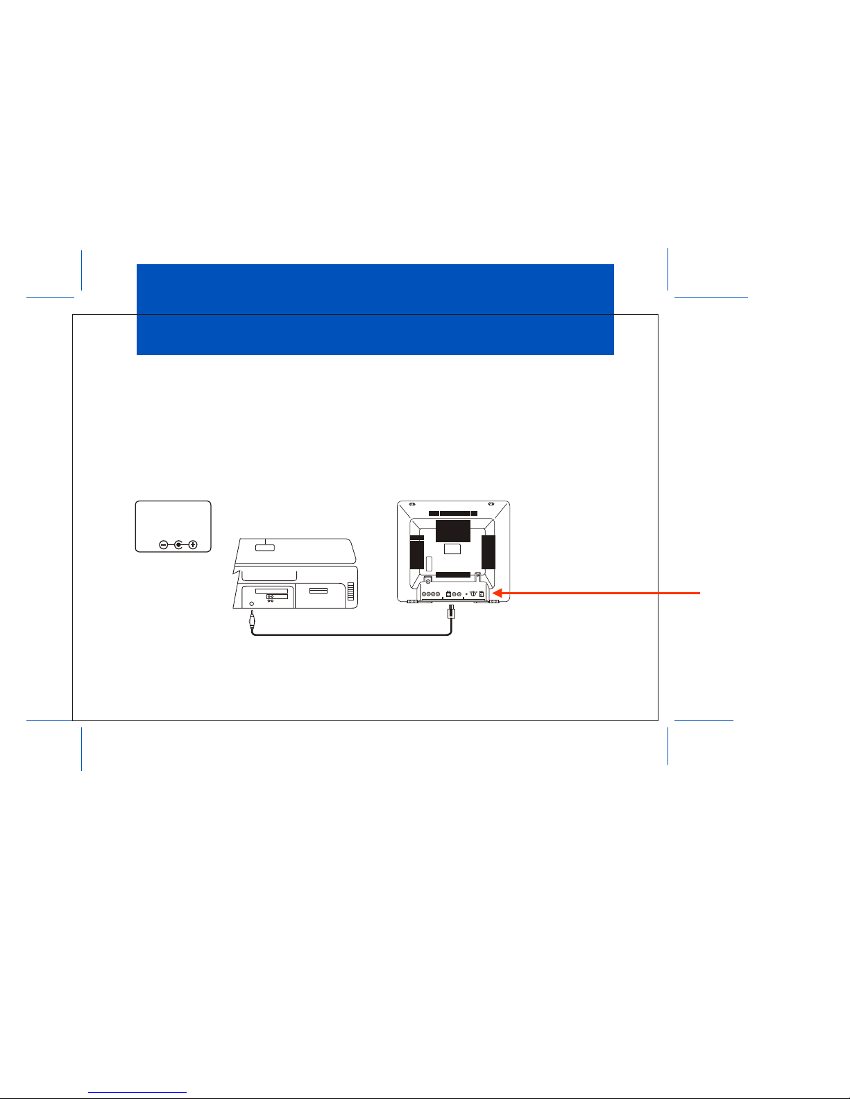
CAR BATTERY OPERATION
A cigarette lighter adapter cable is supplied for use in any 12 Volt, negative ground battery vehicle. Simply
insert the DC plug on the end of the cable into the DC POWER JACK (10) on the back of the TV set, and the
other end of the cable into the cigarette lighter receptacle of the vehicle. The television is now ready for
operation.
Remove plug from cigarette lighter receptacle when unit is not in use
CAUTION:
MEASURE DC SOURCE
POLARITY BEFORE USE
OTHERWISE, THE SET
MAY BE DAMAGED.
GND
Car battery cord
DC JACK
(Rear of TV)
DC JACK
Cigarette Lighter
socket of car (12V)
•
FUSE
T5A/250V
EXT.SPK.
DC INPUT
12-14V
ANT.
INPUT-1
VIDEOAUDIO
OUT
VIDEOAUDIO
DC
12-14V
INPUT-3
VIDEOAUDIO +
–
CAUTION:FORCONTINUED PROTECTION
AGAINTSRISK OF FIRE REPLACE ONLY
WITHSAME TYPE 5A, 250V FUSE .
REVISED DATE : 07/04/03
– DRAWING CHANGE
*
*

1. Front Panel Controls
–2–
AUDIO
INPUT–2
VIDEO
ENTER MENU CHANNEL VOLUME POWER
AUDIO/VIDEO Input Jack
(For “VIDEO 2 MODE”)
AUDIO
INPUT–2
VIDEO
ENTER MENU CHANNEL VOLUME POWER
Æ
Á
Â
Ä
Ã
ÅÀ
VOLUME Button
(Also “ – ” and “+” Buttons)
CHANNEL Button
(Also “ ” and “ ” Buttons)
ENTER Button
MENU Button
Remote Sensor
POWER Button

–3–
À. POWER Button
• Press once to turn on TV.
• Press again to turn off TV.
Á. VOLUME Buttons
• Press VOLUME “+” to increase volume, or press VOLUME “–” to decrease volume.
• The “+” and “–” buttons are also used to adjust the picture. When the PICTURE display disappears
from the screen. These buttons once again become the volume adjustment controls.
Â. CHANNEL Buttons
• Press CHANNEL to see the next higher channel in memory.
• Press CHANNEL to see the next lower channel in memory.
• The and buttons are also used to select desired function on the menu.
Ã. MENU Button
• Press the MENU button, the MENU display appears.
• Press or to select desired function, then press ENTER button to end the choice.
• Details about using each function are on page 11.
Ä. ENTER Button
• To end the choice on the first menu or the second menu.
• Details about using each function are on page 11.
Å. Remote Sensor
• Receives commands from remote control.
• When using the remote control, point it toward this sensor.
Æ. AUDIO/VIDEO Input Jack
• Use a audio/video cable to connect this jack to the audio/video output from a video camera, VCR,
video game, etc.
• These jacks on the front can only be used for direct audio and video input on the “VIDEO 2” mode.

–4–
2. Rear Panel Controls
ANT.
Antenna Jack DC Input Jack Fuse Holder12 11 8
External Speaker Jack
9
AUDIO/VIDEO
Input Jack
(For "VIDEO 1" mode)
AUDIO/VIDEO
Output Jack
11
13
•
FUSE
T5A/250V
EXT.SPK.
DC INPUT
12-14V
ANT.
INPUT-1
VIDEO AUDIO
OUT
VIDEO AUDIO
DC
12-14V
INPUT-3
VIDEO AUDIO +
–
CAUTION:FOR CONTINUED PROTECTION
AGAINTS RISK OF FIRE REPLACE ONLY
WITH SAME TYPE 5A, 250V FUSE.
•
FUSE
T5A/250V
EXT. SPK.
DC INPUT
12-14V
INPUT-1
VIDEO AUDIO
OUT
VIDEO AUDIO
DC
12-14V
INPUT-3
VIDEO AUDIO +
–
CAUTION:FOR CONTINUED PROTECTION
AGAINTS RISK OF FIRE REPLACE ONLY
WITH SAME TYPE 5A, 250V FUSE.
14
AUDIO/VIDEO
Input Jack
REVISED DATE : 07/04/03
– DRAWING CHANGE
*
*
*

–5–
FUSE Holder
• There is a safety fuse in the holder.
• The fuse is a 5-amp, 125/250V (slow blow type).
External Speaker Jack
• You can plug an optional Speaker into this jack for private listening.
• When the plug of an external speaker is attached, the sound will come through the external
speaker instead of the TV speaker.
DC Input Jack
• For car use, the TV is designed for negative (–) ground 12V DC operation only.
• When unit is not in use, remove the car battery cord from the cigarette lighter socket.
AUDIO/VIDEO Input Jack
• Use an audio/video cable to connect this jack to the audio/video output from a video camera,
VCR, video game, etc.
• These jacks on the rear can be used for direct audio and video input on the "VIDEO 1" mode.
ANTENNA Jack
• Connect the antenna cable to the VHF-UHF antenna terminal.
AUDIO/VIDEO Output Jack
• For connection to a monitor TV, audio/video system or VCR.
AUDIO/VIDEO Input Jack
• Use an audio/video cable to connect this jack to the audio/video output from a video camera,
VCR, video game and etc.
• These jacks on the rear can be used for direct audio and video input on the “VIDEO 3” mode.
8 .
9 .
10 .
11 .
12 .
13 .
14 .
REVISED DATE : 07/04/03
– ADD IN ITEM # 14 (AUDIO/VIDEO INPUT JACK)
*
*

–6–
The TV Guidelines set the standard for the TV programs, excluding sports and news. Use the
CH buttons to select, –VOL + buttons to adjust. You can set individual settings with – VOL +
buttons.
The Movie ratings set the standard for movie, video, and other media excluding TV programs. Use
the CH buttons to select, –VOL +buttons to adjust.
The no rating item toggles between “Unblock” and “Block”. This item determines whether the
programs, which are not rated by “Movie Ratings” and “TV Guidelines”, will blocked or not. Use
VOL buttons to change the settings.
The password item will let you change password by entering the V-Chip Control item.
The initial password “1111” should be changed. Use – VOL + buttons to enter the password input
display, and use the number buttons (0-9) to enter a new 4-digit password. After you have entered
the new password, a confirmation display will appear. Punch in the password again.
DESCRIPTION OF PARENTAL CONTROL SETTINGS
1.
2.
3.
4.

–7–
BATTERY INSTALLATION
Before attempting to operate your Remote Control, install batteries as described below.
1. Turn the Remote Control face down. Press down on the ridged area of the battery cover and slide it
off.
2. Install two “AAA” batteries as shown. Make sure that proper polarity (+ or –) is observed.
3. Slide the cover back until it clicks.
+
–
+
–

–8–
REMOTE CONTROL OPERATION
1. TV PARTS:
1. TV POWER
Press this button to turn on the set.
Press the button again to turn the set off.
2. Direct Access (0-9, 1--) Number Buttons
Use these buttons to select a channel.
The channel number chosen will be displayed on the
screen for about four seconds.
To select channels 0-99, press two number buttons.
For example, to select channel 8, press 0, 8.
To select channels above 100, press the 1-- button,
then the number buttons for the last two digits of the
channel.
For example, to select channel 115, press 1--, 1, 5.
3. CHANNEL s/tButtons
Use these buttons to advance to the next higher (s)
or lower (t) channel. (also used to select desired
function on the menu).
4. Volume +/– Buttons
Use these buttons to raise (+) or lower (–) the TV
sound level (also used to make picture adjustments in
picture selector mode).
1
456
7
01-
8
TV POWER
TV/VIDEO
MUTE
PICTURE
SELECTOR
TV/CATV
ENTER
PLAY
REW F.FWD REPLAY STOP
VCP POWER
VOL . +
VOL. –
MENU
CH s
CH t
ERASE/
ADD
AUTO
PROGRAM
9
2 3 8
9
4
5
10
11
12
15
17
13
14
16 18
7
1
6
2
3
–9–
5. MENU Button
Press the MENU button. The MENU display appears.
Use sand t buttons to select desired function, then press ENTER button to end the choice.
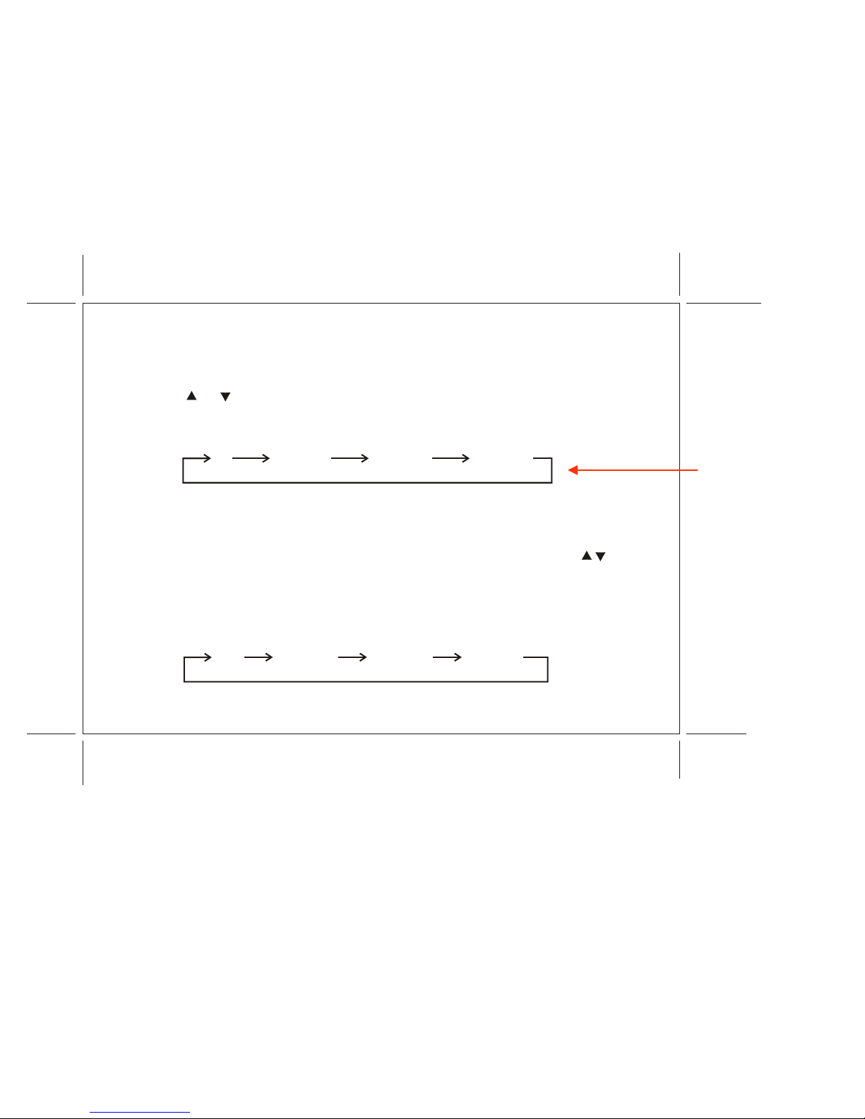
6. TV/VIDEO Button
Press this button to access the AUDIO/VIDEO input jacks, on the front and rear of the TV. As the
button is pressed, the on-screen display will cycle as follows:
7. MUTE Button
Press this button to turn the TV sound off. Press again to restore sound to the previously set level.
MUTE may also be released by pressing the VOLUME +/– buttons.
8. ERASE/ADD Button
This button is used to manually add or erase any channel that is stored in the CHANNEL s/t
memory. The stored channel numbers are displayed in GREEN on the screen and the non-stored
channel numbers are in RED.
9. TV/CATV Button
Use this button to select regular 69-channel broadcast TV or 125-channel cable TV (standard
cable, HRC cable, or IRC cable).
As the button is pressed, the on-screen display will cycle as follows:
TV VIDEO 1 VIDEO 2 VIDEO 3
AIR CABLE-S CABLE-H CABLE-I
REVISED DATE : 07/04/03
– DRAWING CHANGE
*
*

–10–
10. AUTO PROGRAM Button
Select the regular channel broadcast TV or CABLE TV for AUTO PROGRAM. When the AUTO
PROGRAM button is pressed, the TV screen will show an IMPORTANT information screen, all
the channel numbers for TV or CABLE TV will be scanned. The broadcasting signals will be
detected and automatically stored.
11. ENTER Button
Use this button to end the choice on the menu.
Details about using each function are on page 11.
12. PICTURE SELECT Button
Each time this button is pressed the on-screen picture adjustment display cycles through
"adjustment screens" as follows:
IMPORTANT
Reception on any TV in a mobile
environment may be affected by:
Vehicle movement, weather,
distance from TV station, etc..
These factors may cause the
picture to roll, be snowy, and
cause some color loss.
For the best picture quality,
a VCP is recommended.
SCANNING AIR CH : 2–69 (for TV)
or
SCANNING CABLE CH : 1–125 (for CABLE TV)
CONTRAST BRIGHTNESS SHARPNESS TINT COLOR
Then use the VOLUME +/– buttons to raise (+) or lower (–) the level.
The display will automatically turn off if no adjustments are made within four seconds, or if any
other button is pressed.

–11–
2. VCP PARTS:
13. VCP POWER Button
This button is used to turn the unit on and off.
14. "REW" REWIND Button
If this button is pushed while the tape is stopped, the tape will rewind. If this button is pushed
while the tape is playing, the VCP will go into rewind search mode. For more information on
search feature of the VCP, consult VCP owner's manual.
15. PLAY Button
Press this button to activate play mode while a tape is loaded into the VCP. This button may also
be used to dis-engage search and pause modes. For more information, consult the VCP owner's
manual.
16. "F. FWD" FAST FORWARD Button
If this button is pushed while the tape is stopped, tape will fast forward. If this button is pushed
while the tape is playing, the VCP will go into fast forward search mode. For more information on
search feature of the VCP, consult the VCP owner's manual.
17. STOP Button
Press this button to stop the tape.
18. REPLAY Button
During playback, press this button to rewind the tape to the beginning and to begin PLAY mode
from there.

–12–
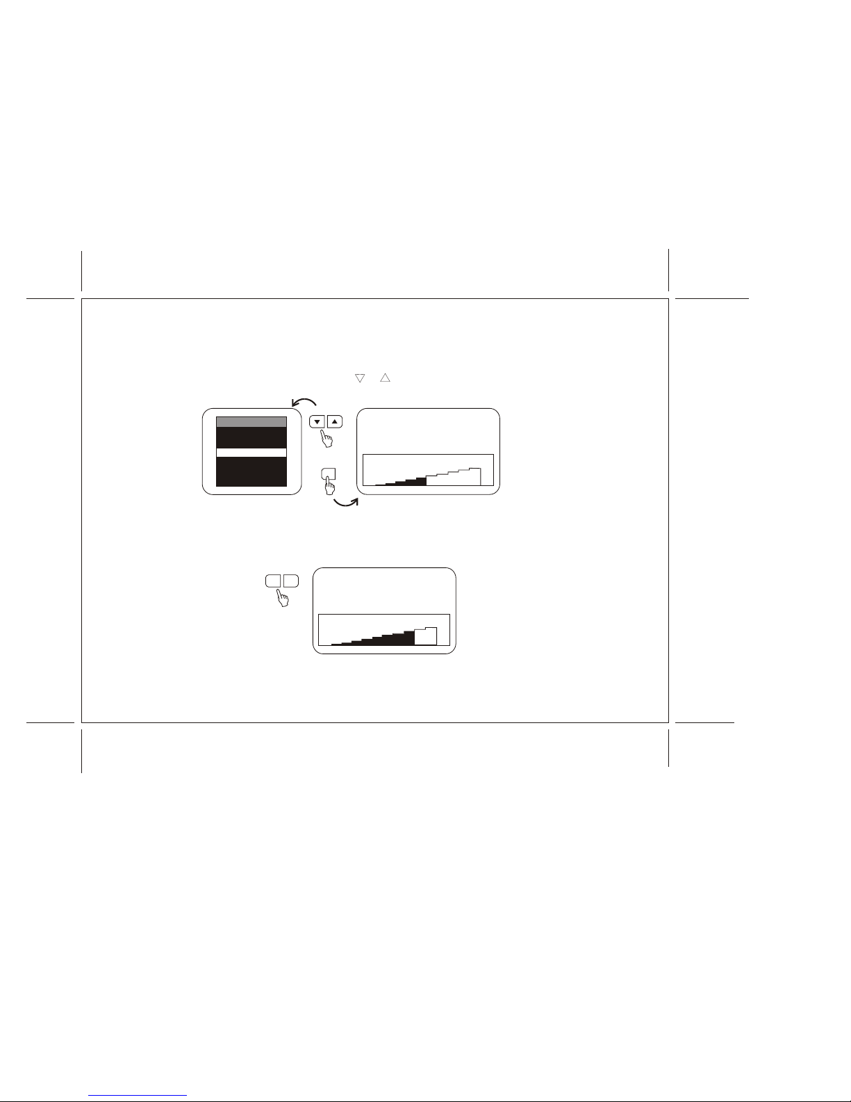
ADJUSTING THE PICTURE
When watching TV programs, the quality of the picture can be adjusted to suit your taste.
1. Press MENU. The main menu appears.
2. Press either CHANNEL sor tto select the function.
Make sure the highlight bar is PICTURE and then press ENTER.
CHANNEL
ENTER
MENU MAIN MENU
SELECT VIDEO
CLOSED CAPTION
SET PICTURE
AUTO-PROGRAM
ANTENNA INPUT
V-CHIP PROTECT
SET PASSWORD
MAIN MENU
SET PICTURE
SELECT VIDEO
CLOSED CAPTION
AUTO-PROGRAM
ANTENNA INPUT
V-CHIP PROTECT
SET PASSWORD
PICTURE
CONTRAST
BRIGHTNESS
SHARPNESS
TINT
RESET
COLOR
–13–
3. Select the item to adjust. For example:
To adjust brightness, press CHANNEL tor sto select BRIGHTNESS and press ENTER.
4. Adjust the level:
Press VOLUME “–” or “+” to adjust the level.
VOLUME
50 BRIGHTNESS
–+
+
–
CHANNEL
32 BRIGHTNESS
ENTER
PICTURE
CONTRAST
SHARPNESS
TINT
RESET –+
BRIGHTNESS
COLOR
Table of contents


