4
IMPORTANT NOTES ( WARNING !)
CHILDREN & PETS
If you have small children or pets, you should consider placing the amplifiers out of reach
to prevent damage to the amplifier or damage to your small children or pets by the
amplifier as the valves do get hot during operation.
WATER & MOISTURE
As with any electrical equipment, these amplifiers should not be used near water or
moisture.
Keep clear of open windows
CLEANING THE AMPLIFIER
Turn off the power on the front panel of the amplifier and remove the power cable from the
mains wall socket completely before cleaning the panels.
## Use a soft cotton cloth or cotton gloves only
## Do not use any water, alcohol, chemicals, or cleaning sprays on any part of the
amplifier chassis or valves
Valves may become loose during transit straighten and press down each tube firmly
before into its appropriate valve socket before plugging the amplifier into the AC mains
socket.
HEAT FROM THE AMPLIFIER
Do not touch the valves after the amplifier has been switched on, as the valves become
very hot during operation and should only be handled after the power has been turned off
and the valves have cooled. Allow at least 15 to 20Minuites for the amplifier to cool down
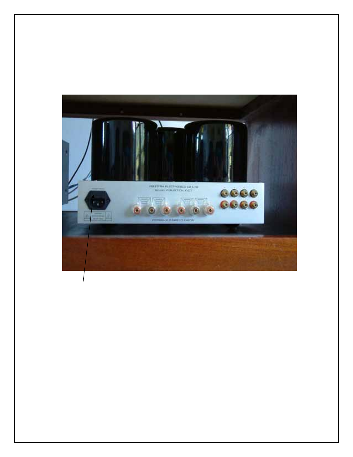
Your amplifier has been factory set to the correct mains voltage for your country.
The voltage setting is marked on the serial badge, located on the rear panel neat the IEC
mains input socket.
Check that this complies with your local main supply.
SHOCK HAZZARD #####
High voltages are contained inside the amplifier
DO Not remove the metal base cover of the amplifier.
DO Not Operate the amplifier with the valves removed from the valve sockets