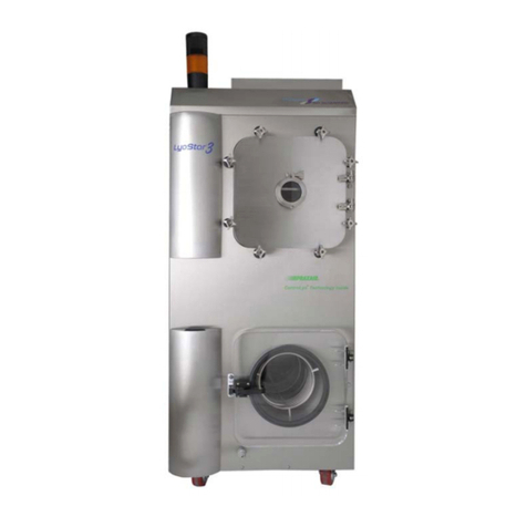
FTS Dura-Dry II User manual

Document # MNL-032-A, Rev. 004, 12/07
Dura-Dry II
Condenser Module
Operator’s Manual
FTS
3538 Main Street
Stone Ridge, NY 12484 USA
www.SPIndustries.com
(800) 251-1531 or 001 (845) 687-0071
SP Service:
(877) 548-4666 or 001 (215) 672-7800
FAX: (845) 687-0024
™

© SP Industries, Inc. Rev.004, 12/07
ii
Notice
This Operation Manual contains confidential and proprietary information of SP Industries, Inc. and
may be used only by a recipient designated by and for purposes specified by SP Industries, Inc.
Reproduction of, dissemination of, modifications to, or the creation of derivative works from this
manual, by any means and in any form or manner, is expressly prohibited, except with the prior
written permission of SP Industries, Inc. Permitted copies of this document must retain all proprietary
notices contained in the original.
The information in this document is subject to change without prior notice. Always confirm with SP
Industries, Inc. that you are using the most current version of this document. SP Industries, Inc. is
free to modify any of its products and services, in any manner and at any time, notwithstanding the
information contained in this document.
THE CONTENTS OF THIS DOCUMENT SHALL NOT CONSTITUTE ANY WARRANTY OF ANY
KIND, EITHER EXPRESSED OR IMPLIED, INCLUDING BUT NOT LIMITED TO THE IMPLIED
WARRANTIES OF MERCHANTABILITY AND/OR FITNESS FOR A PARTICULAR PURPOSE OR
GIVE RISE TO ANY LIABILITY OF SP INDUSTRIES, INC., ITS AFFILIATES OR ITS SUPPLIERS.
The terms and conditions governing the use of this Operation Manual shall consist of those set forth
in written agreements with SP Industries, Inc.
All brand or product names mentioned may be trademarks or registered trademarks of their respective companies.
© 2007 SP Industries, Inc. All marks herein are used under license.

© SP Industries, Inc. Rev.004, 12/07
iii
Contents
Important Symbols......................................................................................................................4
Foreward......................................................................................................................................5
Safety Precautions ...........................................................................................................................5
Inspection .........................................................................................................................................6
Overview......................................................................................................................................7
Installation...................................................................................................................................9
Unpacking.........................................................................................................................................9
Physical Location............................................................................................................................10
Ambient Air Requirements .............................................................................................................10
Electrical Requirements .................................................................................................................10
Vacuum Pump Installation and Maintenance.................................................................................11
Liquid Nitrogen Trap.................................................................................................................12
Installation.......................................................................................................................................13
Operation........................................................................................................................................14
Cleaning..........................................................................................................................................14
Pre-Operational Baseline Performance Test.........................................................................15
System Start-Up........................................................................................................................16
Microprocessor Control Panel ........................................................................................................16
Normal Operation ...........................................................................................................................17
Installation for Manifold Systems............................................................................................18
Installation.......................................................................................................................................19
Installation and Use of Quick-Vac Valves ......................................................................................19
Diagram of Quick-Vac Valves ........................................................................................................20
System Defrost and Shut Off...................................................................................................21
Troubleshooting........................................................................................................................22
General...........................................................................................................................................22
Removing the Condenser...............................................................................................................24
Vacuum Leak Troubleshooting Procedure.....................................................................................25
Maintenance ..............................................................................................................................26
Service & Warranties................................................................................................................28
FTS Warranties and Service Agreements......................................................................................28
Standard Warranty .........................................................................................................................29
Service Options ..............................................................................................................................30
Return of FTS Equipment...............................................................................................................31
Material Safety Data Sheets.....................................................................................................32

© SP Industries, Inc. Rev.004, 12/07
4
Important Symbols
Warning! Refer to manual text. Injury or even death
may result if a recommendation marked with this symbol
is not heeded.
Electric Shock Danger! Use appropriate caution to avoid injury or death.
Burn Danger! Potentially hot surface. Use appropriate caution.
Do not store flammable materials in chamber.
Wear Safety Glasses.
Crush Hazard. Keep hands clear when operating door.
Corrosive Chemical. Wear suitable gloves, safety glasses, and protective clothing.
Property Caution! To prevent damage to chamber equipment and/or load, adhere to
procedures marked by this symbol.
Practical Operating Tip. These recommendations streamline unit operation and prevent
common operator errors.

© SP Industries, Inc. Rev.004, 12/07
5
Foreward
Thank you for buying an SP Industries / Hotpack product. Our goal is 100 percent customer
satisfaction. If you are in any way dissatisfied with your order, please contact us immediately.
Safety Precautions
Your satisfaction and safety will be assured by a complete understanding of this equipment.
To assure your satisfaction and safety, as end user of this equipment, it is the operator’s
responsibility to understand its function and operational characteristics. Before operating this
equipment please read this instruction manual thoroughly. Ensure that all operators receive
appropriate training.
Awareness of the stated cautions and warnings, compliance with recommended operating
parameters, and performance of periodic maintenance requirements are important for safe and
satisfactory operation.
Your instruction and maintenance manual is valuable as it contains information to help you better
understand and operate the equipment you have purchased. It includes a wiring diagram and
contact numbers, which you may require at some future date. Keep it close at hand and refer to it
often. Additional manuals may be purchased from our Parts Department.
If any part of these instructions is not clearly understood, please feel free to contact Customer
Service for clarification.
If you require replacement parts, we must have the model and serial numbers plus all electrical
information from the nameplate.
The unit should be used for its intended application; alterations or modifications will void the
warranty. This product is not intended, nor can it be used, as a sterile or patient-connected
device, nor is it designed for use in Class I, II, or III locations as defined by the National Electrical
Code.
Never use with toxic, corrosive, flammable or organic materials unless special precautions are in
place to prevent injury to personnel or damage to equipment.
Never operate unit without all covers in place.
Never clean with solvents. Use mild detergent and water only.
Never allow hands or body to be exposed to open vacuum ports.
WARNING! FOLLOW THESE INSTRUCTIONS TO AVOID INJURY AND/OR DAMAGE TO
EQUIPMENT.
CAUTION
As a routine safety precaution, always wear safety glasses when working with
this equipment.

Operator’s Manual: Dura Dry II Foreward
© SP Industries, Inc. Rev.004, 12/07
6
Always verify that the electric service and other utilities match the unit’s requirements before
connecting to power.
Always wear safety glasses when using glass flasks.
Always practice team lifting when moving heavy equipment.
Always ensure that refrigeration air intake is clear and clean.
Always ensure that only an authorized technician services the refrigeration, heat transfer,
vacuum and electrical systems.
Always assume that internal parts may be very cold or very hot. Utilize personal protective
equipment to avoid burns.
Inspection
This merchandise was carefully packed and thoroughly inspected before leaving our factory.
Save all packing material if apparatus is received damaged.
Responsibility for its safe delivery is assumed by the carrier upon acceptance of the shipment,
therefore, claims for loss or damage sustained in transit must be made upon the carrier by
recipient as follows:
Visible loss or damage
Note any external evidence of loss or damage on the freight bill, or express receipt, and have it
signed by the carrier's agent. Failure to adequately describe any such external evidence of loss
or damage may result in carrier's refusing to honor your damage claim. The form required to file
such a claim will be supplied by the carrier.
Concealed loss or damage
Concealed loss or damage means loss or damage which does not become apparent until the
merchandise has been unpacked and inspected. Should either be discovered, make a written
request for inspection by the carrier's agent with 15 days of the delivery date; then file a claim
with the carrier since the damage is the carrier's responsibility. By following these instructions
carefully, we guarantee our full support of your claim to be compensated for loss from concealed
damage.
Do not -- for any reason -- return this unit without first obtaining authorization. Please
supply nameplate data, including model number and serial number, in any
correspondence to the manufacturer.
WARNING
DO NOT STORE OR PROCESS FLAMMABLE MATERIALS This unit is
not designed (nor is it intended to be used) for the purpose of processing
or storage of materials that may contain volatile flammable solvents or that
may emit flammable vapors during processing or storage.

© SP Industries, Inc. Rev.004, 12/07
7
Overview
The Dura-Dry II MP Condenser Modules are the most durable condenser modules available. The
stainless steel condenser and stainless steel condenser housing are virtually indestructible
regardless of the acid or solvent your product may contain. This system features a
microprocessor control complete with digital temperature and vacuum indication, as well as
system status and diagnostic indicators to provide you with the most advanced laboratory freeze-
dryer available. The Dura-Dry II MP Condenser Module is available in -85°C condenser
configuration. The Dura-Dry also features a hinged cabinet front for complete accessibility of the
vacuum pump and other internal components, as well as completely visible condenser and
standard hot gas defrost. The result is the most durable condenser module available anywhere.
Additional standard features for the Dura-Dry II MP Condenser Module include a convenient
drain line, stainless steel top work surface, as well as an easily removable condenser. All of these
features are provided to you to insure the most dependable and repeatable freeze-drying
available today.
Front View
1. Chamber Door
2. Microprocessor Control
3. Vacuum Pump Access Door
Model Specifications FD2085
Performance 20 liters per 24 hours with maximum low condenser
temperature at -85°C, MP control
Dimensions W x D x
H
32 x 29.5 x 33.5” (81.3 x 75 x 85 cm)
Weight lbs/kg 435/198
Electrical130A without vacuum pump
1Available for 208V/60Hz, 220V/50Hz or 200V/50Hz. Vacuum pump electrical requirements are not included.
Add 6A for vacuum pump. All high voltage components are located in an enclosed electrical housing to meet
international standards.
1
3
2
Options: Can be used as a
manifold system with the
Dura-Port manifold, or at any
time in the future as a tray
dryer with the stoppering or
bulk tray dryer chambers.

Operator’s Manual: Dura Dry II Overview
© SP Industries, Inc. Rev.004, 12/07
8
Rear Panel Hookups
1. Communication Port
2. Sterile Air Inlet
3. Circuit Breaker
Right Side Condenser Ventilation
12
3

© SP Industries, Inc. Rev.004, 12/07
9
Installation
Unpacking
The Dura-Dry II MP is packed and shipped complete with vacuum pump in its own carton.
Certain items, such as a Liquid Nitrogen Trap, will be shipped in a separate container.
Remove from the packing material and make a visual inspection for shipping damage.
Concealed damage can occur even if the crate or carton is undamaged. This damage is the
responsibility of the transportation company. If the equipment has suffered shipping damage,
contact the transportation company immediately. All packing material must be kept for their
inspection.
FTS carefully tests all products thoroughly for quality and operational specifications prior to
shipment. The products are adequately packed to ensure their quality and operational status.
Before placing the unit in its permanent location, record the following information.
9Serial Number__________________________
9
9Model Number_________________________
9
9Electrical Requirement___________________
NOTE:The above information is located on a tag in the rear of the machine where the line cord
enters the machine.
If you need to contact FTS regarding the performance or operation of the unit, the above
information will allow us to respond in a more timely fashion.

Operator’s Manual: Dura Dry II Installation
© SP Industries, Inc. Rev.004, 12/07
10
Physical Location
The Dura-Dry II MP Condenser Module is mounted on heavy-duty casters and may be rolled
into place at this time. Since this is an air-cooled system it requires adequate airflow and an
ambient of approximately 75°F (25°C). The rear of the system, and any condensing fins
exposed in the sides of the unit, should have at least six inches of clearance from any
obstructions. If the airflow is obstructed, or the ambient is not +/- 5°F (+/-3°C) the system will
not meet specifications. The system should be relocated to a more suitable location or
additional room ventilation should be provided.
Ambient Air Requirements
Electrical Requirements
There will be one power line cord running from the rear of the Dura-Dry II MP. The serial tag at
the rear of each system has the voltage requirements for that system. The voltage tolerance for
this system is +/-5%. These tolerances are necessary because of the lower temperature
specifications of these units. Check the voltage requirements as stated on your serial tag
against your power supply.
All Dura-Dry II MP units are shipped with NEMA 6-30P plugs (except units sold overseas; no
plug). We recommend a 30A supply with a NEMA 6-30R outlet. The plug with ground needs to
be connected to a grounded outlet at the supply. The maximum current draw (utilizing the
largest standard pump) is 16A/60Hz or 21A/50Hz. Avoid the use of extension cords
whenever possible. If an extension cord is required, it should be of sufficient size to supply 30
amps without heating
55°F to 69°F (12°C to
21°C) Acceptable
70°F to 75°F (21°C to
24°C) Ideal
75°F to 80°F (24°C to
27°C).
Acceptable, but a reduction in the cooling capacity of the
unit is to be expected (about a 1% cooling capacity
reduction per degree above 72°F).
80°F to 85°F (27°C to
29.5°C) Expect reduced reliability. Warranty may be voided.
Over 85°F (Over
29.5°C) Not Acceptable. Warranty will be voided.
NOTE: These systems will not work properly on voltage other
than that ordered and specified. If incorrect voltage has been
ordered, contact the FTS Service Department and they will
recommend the a
pp
ro
p
riate transformer

Operator’s Manual: Dura Dry II Installation
© SP Industries, Inc. Rev.004, 12/07
11
Vacuum Pump Installation and Maintenance
•Before running the system, make sure the vacuum pump oil is full by visually observing the
sight glass on the pump.
•Make sure the drain hose is plugged and doors are closed before pulling a vacuum.
•Make sure vacuum pump oil is clean prior to each run.
•Attach Oil Mist Eliminator before running.
Note on High Vapor Pressure Solvents
If your product contains high vapor pressure solvents you should perform the beginning of your
run (after introducing the product) with the gas ballast open. This should not be done without an
Oil Mist Eliminator, as the pump will expel vacuum pump oil. Should there be concern with
regard to the vapors being expelled by the pump in the immediate environment a nonrestrictive
line should be put on the outlet of the pump and run to a fume hood.

© SP Industries, Inc. Rev.004, 12/07
12
Liquid Nitrogen Trap
This trap is sold as an option and may not be included with your unit. The liquid nitrogen trap
(LNT) is connected to a freeze-dryer when it is important to trap high vapor pressure solvents.
Typically these solvents come off of product early in the cycle. During this time the LNT can be
valved so it is on line. When the pressure in the system decreases, indicating that the high
vapor pressure solvents are gone, the LNT can be valved off line. This will allow the most
economical use of liquid nitrogen.

Operator’s Manual: Dura Dry II Nitrogen Trap
© SP Industries, Inc. Rev.004, 12/07
13
Installation
The LNT is shipped separately and will need to be installed on the Dura-Dry II MP.
1. Bolt the LNT shelf to the right side of the Dura-
Dry II MP with the inlet and outlet tubing
entering the appropriate holes in the cabinet.
2. Open the door of the Dura-Dry.
3. Attach the tubing from the vacuum pump to
the upper tube from the LN2 Trap with a hose
clamp.
4. Attach the tube from the condenser to the
bottom (inlet) tube with a hose clamp.
Installed LNT
1
2
3
4

Operator’s Manual: Dura Dry II Nitrogen Trap
© SP Industries, Inc. Rev.004, 12/07
14
Operation
LNT on-line:
1. Open the inlet and the outlet valves while making certain the by-pass valve is closed.
2. Pour liquid nitrogen into the center pot. There should be liquid nitrogen in the center pot
whenever the LNT is on-line and trapping high vapor pressure solvents.
3. The lid should be placed on the trap but should not be anchored down in any way. This
top configuration allows the liquid nitrogen vapor to escape in a way that avoids
excessive pressure build up.
4. To place the LNT on by-pass, open the by-pass valve and close the inlet and outlet
valves.
Cleaning
1. Make sure that the LNT is off line.
2. Break vacuum by removing the LNT drain plug if necessary.
3. Take the center trap out and clean it in a sink.
4. Allow the condensate in the pot to melt or accelerate the defrost by adding warm water.
5. Drain the condensate from the pot by using the drain line.
6. Rinse the pot down with water and wipe it dry.
7. Reassemble.

© SP Industries, Inc. Rev.004, 12/07
15
Pre-Operational Baseline
Performance Test
It is always advisable to make a pre-operational test of all instrumentation. This routine
precautionary measure will insure that your system is functioning properly before you introduce
valuable product that may be damaged or lost due to inadequate vacuum or refrigeration. This
also allows you to acquaint yourself with the different features of the Dura-Dry II MP Condenser
Module.
1. At the top of the Dura-Dry II MP Condenser Module is a test plug that is inserted into a black
rubber grommet. Remove the test plug by moving it side to side while pulling up. Avoid using a
rotational movement as this may cause the black rubber grommet to come out of round.
2. Once the test plug is removed check to make sure that the black rubber grommet is round when
looking at it from a bird's eye view. Grease this grommet with a high grade, heavy-duty vacuum
grease and replace the test plug with a downward motion.
3. Check to make sure that all the openings to the system (condenser drain port, acrylic end plates,
etc.) are closed.
4. Start the system as described on the following page.
The maximum low condenser temperature and vacuum achieved by the system should be
recorded in this manual. This will provide a baseline performance specification for the system and
can be used for future comparison.
Maximum Low Condenser Temperature
Amount of Time to reach Max Low
Minimum Vacuum
Ambient Temperature

© SP Industries, Inc. Rev.004, 12/07
16
System Start-Up
Microprocessor Control Panel
1. Turn ON the main power switch on the front panel of the Dura-Dry II MP Condenser Module. This
switch is also a circuit breaker. If the unit draws too much current, the breaker will switch to the
OFF position.
2. On the front of the microprocessor is a START/STOP key. Press this key until you hear an
audible beep. A two to three second delay has been built into this keypad to prevent inadvertent
activation of the system.
3. The system will start up in the correct sequential order. The red out-of-range light labeled
VOLTAGE will light for about two seconds when power is first applied to the system. If this red
light remains on then the voltage supply is too low to run the system. The START/STOP keypad
should be pressed thereby deactivating the system. The voltage supply at the wall should be
checked. The wall voltage must be within 5% of the voltage listed on the serial tag. The voltage
may need to be checked while the Dura-Dry II MP is running since open circuit voltage may be
correct, but inadequate wiring has caused the power delivered to the machine to drop. A
buck/boost transformer may be necessary if adequate voltage cannot be provided. The Dura-Dry
II MP can be operated with low voltage for short periods of time, but you may not reach ultimate
low on temperature or vacuum. Additionally the operation of the system on inadequate power
may significantly reduce the life of the system.
4. Allow the system to stabilize for a period of 15 to 30 minutes. A dry clean and empty system
should indicate a condenser temperature at or below the maximum low specified. The pressure in
the system should register between 10 to 30mT. If a good vacuum is not achieved please refer to
the vacuum trouble shooting procedure section of this manual. If the system does not achieve
specifications please call the FTS Service Department or your local representative.
5. Once you have determined that the system is working properly, turn off the system by pressing
the DEFROST keypad. The system will turn itself off in the correct sequential order.
If you use the main power ON/OFF switch to deactivate the system it will interpret this as a power
interruption. The next time the system is turned on the power interruption safety loop will be
activated and you will be signaled that a power interruption has occurred.
The product addition station that you have ordered (Tray Dryer or Manifold system) should be
added to the system at this time. Please refer to the instructions for your product addition station.

Operator’s Manual: Dura Dry II System Start-Up
© SP Industries, Inc. Rev.004, 12/07
17
Normal Operation
The following operational instructions are to be used when the product addition station is a
manifold system or a Tray Dryer with digital control (STD or BTD systems) capabilities. If you
have a Microprocessor Controlled Tray Dryer, the Dura-Dry II MP Condenser Module
microprocessor is a slave to the microprocessor in the Tray Dryer MP and the instructions for use
are in the Microprocessor Controlled Tray Dryer Instruction Manual.
1. Push START/STOP key until you hear an audible signal (beep).
2. The Dura-Dry II MP Condenser Module compressor(s) will activate. The condenser temperature
is digitally displayed on the TEMPERATURE indicator. On the left side of the temperature
indicator readout is a small green indicator light. When the refrigeration is activated this light
should go on.
3. When the condenser temperature reaches -40°C, the vacuum pump will turn on within 5 seconds.
The VACUUM digital readout will indicate 3HHH when the vacuum is above 3,000mT. Below
3,000mT it will indicate the system vacuum. When the vacuum pump is activated, the green
Indicator on the left side of the vacuum readout display will light up.
4. The ADD product light will turn green when the vacuum reaches 500mT. The system is now
ready for product addition.
When using a manifold system: Add one of your product containers with prefrozen product.
The ADD light will go off. Do not add another container until the ADD light turns green, thus
indicating that the system is ready to accept another container. Continue to add product
containers, one at a time, making sure that each time the ADD light indicator is on.
When using a STD or BTD Tray Dryer: You may begin to add heat to your product as outlined
in the Tray Dryer Instruction Manual.

© SP Industries, Inc. Rev.004, 12/07
18
Installation for Manifold Systems
1. Chamber door
2. Microprocessor control
3. Vacuum pump access door
4. CA-3 manifold adapter
5. MS-14 14 port manifold
6. Support rod
7. Coupling
8. Drip pan
7 5 6
2
3
1
8
4

Operator’s Manual: Dura Dry II Manifold System Installation
© SP Industries, Inc. Rev.004, 12/07
19
Installation
1. Remove the 2½-inch stainless steel plug from the Dura-Dry II MP Condenser Module.
2. Grease the bottom of the CA-3 port.
3. Insert the CA-3 into the port on the top of the Dura-Dry through the black rubber
grommet.
4. Screw the three rods together and screw the assembled rod into the top of the Dura-
Dry.
5. Clamp rubber couplings on all CA-3 ports.
6. Insert manifold(s) and clamp to the rubber couplings.
7. Attach manifold(s) to the rod with brackets provided.
NOTE: If 1 or 2 manifolds are ordered, place white cap on the unused ports of the CA-
3.
NOTE: CA-6 is also an option that contains 6 ports for 6 manifolds.
Installation and Use of Quick-Vac Valves
1. All ports have been greased at the factory. If additional grease is needed, FTS
recommends Dow Corning or equivalent high vacuum grease.
2. Place Quick-Vac valves on each port. Note that one end of the valve contains a slight
rise or bump, referred to as the Index Boss. This end of the valve is placed away from
the manifold (see diagram on following page).
3. Make sure all valves are in the closed position (see diagram).
4. Quick-Vac valves accept ½ inch lipped flaskware. FTS also carries 3/4-inch valves if
required.
5. While performing a run, add each sample one at time by slowly opening the Quick-Vac
valve. When the Dura-Dry is ready for the next sample, the ADD PRODUCT light will
illuminate.
IMPORTANT: Before removing flaskware, open valve to the venting position (see diagram).

Operator’s Manual: Dura Dry II Manifold System Installation
© SP Industries, Inc. Rev.004, 12/07
20
Diagram of Quick-Vac Valves
The inside of the Quick-Valve is designed to accept lipped flaskware such as that on a serum
bottle. All FTS flaskware is manufactured with this lip. If you are using another manufacturer’s
flaskware, you ma be able to introduce it into the Quick-Vac Valve with no difficulty. FTS also
manufactures Quick-Vac Valves that accept flaskware with ¾ inch OD necks. These are called
QV-2 Valves and can be purchased directly from FTS at 800.251.1531.
Open to Sample
Open to System
Sample Vented to
Atmosphere
Closed to System
Closed to Sample
Open to System
Table of contents
Other FTS Dryer manuals