GT-HR Multi-Functional Readout
3!
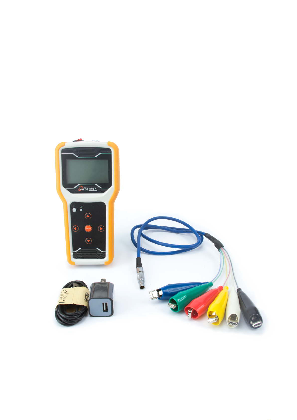
Product Introduction
GT-HR Multi-Functional Readout (Herein called GT-HR) is an instrument designed to
provide precise readings of any kind of sensors including DC-voltage, AC-voltage, and
Vibrating-Wire type sensors. It is suitable for measuring sensors such as strain gages, LVDT,
piezometer, tiltmeter, load cell, EL-beam, DSM sensor, etc. While measuring the reading of
a sensor, GT-HR could transmit an excitation voltage, and could directly read feedback
voltage as reading from sensor. Thus, the data of sensor, site temperature, and current
battery capacity could be measured and displayed on its screen. The user could select and
display the language in Traditional Chinese or English. GT-HR also has LED backlight display.
For different kind of sensor, the user should select the excitation voltage. For vibrating-wire
related measurement, GT-HR has 6 position switches, and temperature measurement. It is
powered by lithium battery, which could be charged by using USB Micro connector. The
long standby time and short charging time allow this instrument to be conveniently used
on the construction site.
GT-HR could generate DC and AC excitation voltages, which could be set at 2.5V, 5V to 12V.
The output voltage reading of sensor is then measured and displayed on the screen.
Besides that, GT-HR could also provide current measurement for 2-wire 4-20mA sensors.
For this measurement, 12V DC excitation will be excited to sensor, and the respective
output current from sensor will be measured. For vibrating wire sensor measurement,
6-types of position modes (A-F) are selectable for measuring different types of sensors.