Harnisch+Rieth P-G 400/4 User manual
Maschinenbau
Werkzeuge
Laborgeräte
Operating instructions
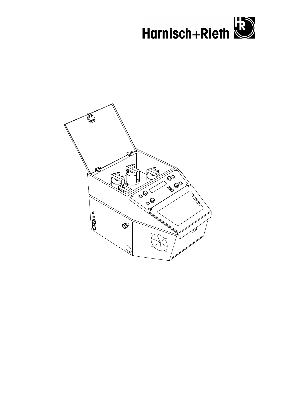
Machine designation: Spot blasting unit
Machine type: P-G 400/4
Machine no.: .......................
Keep for future reference!
Hausanschrift:
Harnisch+Rieth
GmbH & Co. KG
Küferstr. 14 - 16
D-73650 Winterbach
Telefon
+49 7181 / 96 78-0
Telefax
+49 7181 / 7 31 39
+49 7181 / 96 78-17
E-mail:
info@hr-dental.de
http://www.hr-dental.de

P-G 400/4 - 18.04.2013 / Vers.: 1
1
Dear Customer
We appreciate the confidence you have placed in us by buying this spot blasting unit.
We ask you to take your time to carefully read this operating manual, in particular before initial
operation of the unit so that you will benefit from the unit's advantages for many years.
Table of Contents
1
Safety.................................................................................................................................. 2
1.1
Intended use........................................................................................................... 2
1.2
Sources of danger .................................................................................................. 2
1.3
The unit's safety equipment.................................................................................... 2
1.4
Authorized operators .............................................................................................. 3
1.5
Safety measures at the site of operation ................................................................ 3
1.6
Identification of the safety remarks in this manual.................................................. 3
2
Start of Operation.............................................................................................................. 3
2.1
Unpacking the spot blasting unit............................................................................. 3
2.2
Identification and description of the unit components............................................. 4
2.3
Starting Process ..................................................................................................... 5
3
Operation............................................................................................................................ 6
3.1
Connecting the spot blasting unit to the necessary exhaust unit............................ 6
3.2
Connecting the spot blasting unit to the compressed-air supply ............................ 6
3.3
Filling the blasting agent into the blasting agent container..................................... 7
3.4
The blasting systems and their appropriate blasting agents and nozzles .............. 8
3.5
Activating the blasting chamber illumination and exhaust unit ............................... 8
3.6
Activating the desired blasting system (automatic recognition).............................. 9
3.7
Adjusting the operating pressure (blasting pressure) ............................................. 9
3.8
Dosing the blasting agent amount .......................................................................... 9
3.9
Adjusting and saving further operating parameters.............................................. 10
3.9.1
Adjustments after agreement with the Technical Service of H+R ................ 10
3.10
Automatic "Reserve" level indication .................................................................... 10
3.11
LED display........................................................................................................... 11
3.12
Changing or cleaning the blasting nozzles ........................................................... 12
4
Cleaning/Maintenance..................................................................................................... 13
4.1
Checking the blasting hoses................................................................................. 13
4.2
Replacing the blasting hoses................................................................................ 15
4.3
Maintenance ......................................................................................................... 16
5
Electrical Protection........................................................................................................ 16
6
Technical Data ................................................................................................................. 16
7
Warranty conditions ........................................................................................................ 17
8
EC declaration of conformity.......................................................................................... 18

2
P-G 400/4 - 18.04.2013 / Vers.: 1
1 Safety
1.1 Intended use
The spot blasting unit P-G 400/4 is applied in dental laboratories:
−for roughing the framing adhesive surfaces in ceramic lining technology
−for roughing and pre-treating the framing adhesive surfaces in plastic lining technology
−for blasting before special coating
−for shaping ceramics, including chewing surfaces
−for removing the residues of embedding materials, oxides and ceramics
−for polishing.
For safety reasons, unauthorized retrofits and changes are not permitted.
Caution
The unit is not designed as a medical device!
Use on people is prohibited!
1.2 Sources of danger
The spot-blasting unit P-G 400/4 is safe if properly used, but in the case of incorrect or
negligent operation, there is a danger of hurting oneself with the sand jet emanating from the
blasting stylus or blasting hose (injury to skin or eyes).
−Never use the blasting stylus outside the protective blasting chamber, i. e. do not lead the
blasting hose out of the unit. Never look into the installed blasting nozzle or into the
blasting hose without installed nozzle (risk of eye injury)!
−Disconnect the power supply from the unit for maintenance or repair purposes (remove
power plug). If necessary, remove pressure from the unit.
−Disconnect the power supply from the unit before accessing the integrated electric devices!
1.3 The unit's safety equipment
−If the front cover with window is opened, the blasting function will be interrupted by means
of a safety switch.
−If the cover of the blasting agent container chamber is opened, compressed air supply to
the blasting systems will be interrupted by means of a safety switch.
−By opening the safety screw of the housing's upper part, the sand jet shut-off devices are
activated through a pneumatic valve.
−All electrical functions (including blasting chamber illumination) are designed with low-
voltage safety power.
−A pre-pressure control protects the unit against over-pressure.

P-G 400/4 - 18.04.2013 / Vers.: 1
3
1.4 Authorized operators
The owner of the unit must provide the operator with the operating manual and ensure that he
has read and understood it. Only then is the operator authorized to put the unit into operation.
1.5 Safety measures at the site of operation
The installation surface must be even and stable and have the necessary carrying capacity in
accordance with the unit's weight.
The unit must be connected to an exhaust unit.
Danger
The unit is not suitable for use in rooms where special conditions exist (e.g. corrosive or
potentially explosive atmospheres).
1.6 Identification of the safety remarks in this manual
Remark Indicates application tips and other particularly useful information.
Attention
Indicates operating or handling measures, which can lead to faults, damage and other
problems in the case of non-observance.
Danger Indicates dangerous situations, which can lead to injury.
2 Start of Operation
2.1 Unpacking the spot blasting unit
1.
Put the box on an even surface.
2.
Open the box from above and remove the packing material.
3.
The unit must be lifted out of the carton by 2 people (approx. 45 kg).
4.
Check the accessories.
−Documentation
−Foot pedal with cable and plug .............................................................................. No. 67010
−Power supply cable ................................................................................................ No. 35028
−2 m PVC fabric hose, blue, Ø 8.2 x 6 with
quick-coupling adapter sleeve and swivel nut........................................................ No. 72350
−for possible further accessories, see delivery note

4
P-G 400/4 - 18.04.2013 / Vers.: 1
2.2 Identification and description of the unit components
Main elements of the spot blasting unit P-G 400/4:
a)
Sheet-steel housing with blasting chamber and connection for external exhaust unit.
b)
4 blasting units, consisting of a blasting agent container, mixing chamber, vibrating unit for
exactly controlling the desired amount of blasting agent, blasting hose with blasting stylus,
electrical-pneumatic cut-off for starting or stopping the sand blast.
c)
Device, which serves to automatically activate the blasting unit of the selected blasting stylus.
d)
Electronic selection device for adjusting the blasting agent portion in the sand jet, with digital
display.
e)
Pressure regulator for adjusting the jet pressure, with digital display
f)
Automatic "Reserve" level indication, with digital display
Fig. 1: View of unit from front left-hand side
4/1
Blasting agent container white 25
4x wing screws
4/2
Blasting agent container yellow 27
4x stirrups
4/3
Blasting agent container green 28
2x window holders (left and right)
4/4
Blasting agent container red 40
Front cover with window
8
4x vent screws 41
Front cover lock
11
Front ventilation openings 50
2x unit main fuses 8 A/T
12
Operating panel 51
Unit fuse in front of transformator 1 A/T
15
4x blasting agent container lids 52
Unit fuse subsequent to transformator 5 A/T
18
2x exhaust hose connections
(right and left)
53
Power supply (230 V/ 50 Hz)
20
2x hand openings (right and left) 54
Main switch
23
Cover of blasting agent container
chamber
57
Upper part of housing
24
Cover lock 58
Safety screw for upper part of housing

P-G 400/4 - 18.04.2013 / Vers.: 1
5
2.3 Starting Process
(see Fig. 1 page 4 and Fig. 3 page 6)
1.
Connect the spot-blasting unit to the compressed air supply, see section "3.2".
2.
Connect the spot-blasting unit to the necessary exhaust unit, see section "3.1”.
3.
Fill in blasting agent, see section "3.3” and "3.4”.
4.
Connect foot pedal with socket (13) for the foot pedal on the right-hand side of the unit.
5.
Insert power supply cable (230 V/50 Hz) in the power supply connector (53).
Remark On switching on the main switch (54), the unit is ready to operate in electrical aspects. The
blasting chamber illumination is activated, see section "“3.5”.
6.
Activate the desired blasting system (automatic recognition), see section "3.6”.
7.
Adjust operating pressure (blasting pressure), see section "3.7”.
8.
Dosing of blasting agent amount, see section "3.8”.
5 A/T
1 A/T
8 A/T
I
0
2
3
2
7
2
5
1
5
1
6
2
1
4
0
4
1
3631442242 464843 49
Küferstr.14-16,73650Winterbach
Harnisch+Rieth
MadeinGermany
Maschinen-Typ
Maschinen-Nr.
Baujahr
Spannung
Frequenz
Leistungsaufn.
Luftanschluß
Volt
Herz
Wa tt
bar/max.
P-G 400
1997
230
50
80
9
2654
4
55 6059
4
Fig. 2: View of the unit from the left-hand side
4
4x blasting agent containers 40
Front cover with window
8
4x vent screws 41
Front cover lock
15
4x blasting agent container lids 42
4x pneumatic cylinders (hose clamping)
16
2x safety switch 43
4x mixing chambers
21
blasting chamber illumination 44
Blasting stylus holder
22
4x bases (hose clamping) 46
4x clamping cylinder housings
23
Cover of blasting agent container
chamber
48
4x hose clamps
25
4x wing screws 49
4x adapter sleeves
26
4x blasting hoses 54
Main switch
27
4x stirrups 55
Gas spring
31
4x blasting styluses 59
Cover sheet
36
Perforated sheet, 2 parts 60
Fastening screw

6
P-G 400/4 - 18.04.2013 / Vers.: 1
Fig. 3: View of the unit from the back, right-hand side
3 Operation
3.1 Connecting the spot blasting unit to the necessary exhaust unit
(see Fig. 1 page 4 and Fig. 3 page 6)
The air to be sucked off enters mainly through the front ventilation openings (11), is
conducted along the bottom of the unit and thus always keeps the blasting chamber free of
dust and sand. In addition, air is sucked in through the hand openings (20).
Attention
The spot-blasting unit P-G 400/4 may only be operated with exhaust unit.
1.
Connect the exhaust unit to the right-hand or left-hand connector (18) (Ø 47 mm). The
connector (18) which is not required must be closed with the plastic lid supplied.
2.
Connect exhaust unit to power supply connector (17) (230V). Maximum electrical connection
value 1000 Watt.
3.
Please observe the operating manual of the exhaust unit.
Remark We recommend using our suitable one-place exhaust unit D-LE 255 “S”.
3.2 Connecting the spot blasting unit to the compressed-air supply
(see Fig. 3 page 6)
1.
Connect the compressed-air supply to the pre-pressure control (14) using the fabric hose
supplied.
Attention
Use moisture-free and oil-free compressed air only.
2.
Input pressure is factory-adjusted to approximately 7 bar on the pre-pressure control (14).
Please correct this value if required.
Remark Lifting adjustment knob (19)
Pressing adjustment knob (19)
=
=
unlocking.
locking.
13
Connector for foot pedal
14
Pre-pressure filter control
17
Connector for exhaust
system
19
Adjustment knob
(prepressure)
61
Compressed-air supply
hose
62
Coupling connector

P-G 400/4 - 18.04.2013 / Vers.: 1
7
3.3 Filling the blasting agent into the blasting agent container
(see Fig. 2 page 5)
−
The blasting agent tends to absorb moisture from the air. For this reason, the containers
must be kept tightly sealed and stored at room temperature of at least 20°C
−
The blasting agent tends to become humid particularly during transportation in cold seasons,
which leads to loss of its flowability and to disturbances in the spot blasting unit.
−
Before being filled into the spot blasting unit, humid blasting agent must be dried for
approximately 30 minutes at approx. 60°C.
Attention
To avoid disturbances please ensure that no dirt particles and no larger grain sizes as
indicated are mixed in the blasting agent.
1.
Switch off unit on the main switch (54) and remove power plug.
2.
Open cover (23) of the blasting agent container chamber.
Attention
Before opening the blasting agent containers (4/...), the small vent screws (8) are to be
opened in general. Thus, the pressure in the blasting agent containers can escape, and the
wing screw (25) is relieved.
3.
Open wing screw (25) until stirrup (27) can be swung to the side.
4.
Remove lid of blasting agent container (15).
Remark We recommend using our H+R handle bottles with practical filler neck. The filler neck must
be tightly sealed with the red plastic cap after filling (see above, 1
st
section).
5.
Fill in blasting agent, as described in section "3.4". Fill the blasting agent containers (4/...) to
a maximum of approximately 2 cm below the upper edge.
Attention
Clean the upper edge of the blasting agent container and the O-ring seal before placing the
lid on the blasting agent container.
6.
Place lid on the blasting agent container (15).
7.
Swing stirrup (27) over the blasting agent container lid (15) until the stop has been reached
and fasten wing screw (25).
8.
Close vent screws (8) tightly.
9.
Close cover (23) of blasting agent container chamber.
Remark With cover (23) opened, compressed air supply to the blasting systems is interrupted by
means of safety switch (16).
10.
The unit can be put into operation.

8
P-G 400/4 - 18.04.2013 / Vers.: 1
3.4 The blasting systems and their appropriate blasting agents and nozzles
(see Fig. 2 page 5 and Fig. 4 page 8)
Blasting stylus (31), blasting agent container (4) and operating panel (operating pressure
regulator (9) and pressure switch (5)) of each of the four blasting systems is marked with the
color white, yellow, green or red.
The blasting systems are factory-set as follows:
(On request, we also deliver blasting nozzles with Ø 0.4; 0.8; 1.2; u. 1.8 mm.)
Blast
system
Micro
nozzles-Ø
Type of blasting agent
Class of blasting
agent
Smallest
permissible Ø of
the micro
nozzles
white 0.6 mm special fused alumina Cl. 55 A (50 µm) 0.6 mm
yellow 0.6 mm special polish blasting
medium
(aluminium oxide)
Cl. 30 B (50 µm)
Cl. 20 B (20 µm)
0.6 mm
0.4 mm
green 1.5 mm special polish blasting
medium
(aluminium oxide)
EW 80 (180µm)
EW 60 (250µm)
1.0 mm
1.2 mm
red 1.0 mm special polish blasting
medium
(aluminium oxide)
Cl. 60 B (120µm)
Cl. 150 A (150µm)
0.8 mm
1.0 mm
Attention The unit has been designed for the use of H+R blasting agents.
We do not assume any guaranty in the case of disorder or damage, occurring due to the use
of other blasting agents or incorrect grains.
Fig. 4: Operating panel
5/...
4x push buttons with control light 9
4x operating pressure regulators
6
Push button for increasing the blasting
agent portion in the spot blast
10
Display
7
Push button for reducing the blasting
agent portion in the spot blast
3.5 Activating the blasting chamber illumination and exhaust unit
(see Fig. 2 page 5 and Fig. 4 page 8)
The blasting chamber illumination (21) is activated when the main switch (54) is switched on.
The illumination switches off automatically after approximately 20 seconds (the time can be
set) if the device is not used. Automatic switching-off of the illumination is only possible if all
the blasting stylusses are in their holders.

P-G 400/4 - 18.04.2013 / Vers.: 1
9
The blasting chamber illumination is activated when the main switch is switched on:
1.
by pressing one of the keys (5) or
2.
by pressing the pedal switch or
3.
by withdrawing one of the blasting stylusses (31) from the holder (44).
The blasting chamber illumination remains switched on for as long as a blasting stylus is
withdrawn.
The vacuum extraction switches on automatically by actuating the pedal switch while the main
switch is switched on and a blasting stylus is withdrawn. The vacuum extraction switches off
after approximately 7 seconds if the pedal switch is no longer actuated (the time can be set).
3.6 Activating the desired blasting system (automatic recognition)
(see Fig. 2 page 5 and Fig. 4 page 8)
1.
All blasting styluses (31) must be inserted in the blasting stylus holders (44) according to
their color marking.
2.
By removing the desired blasting stylus from the blasting stylus holder, the corresponding
blasting system is automatically activated.
3.
The operating parameters (dosing the blasting agent amount and operating pressure), as
adjusted during last use of this blasting system, are taken over and indicated in the display
(10).
4.
The sand blast is activated with the foot pedal.
Attention
If the front cover (40) or the cover (23) of the blasting agent container chamber is not
completely closed, the sand blast cannot be activated. After activating the foot pedal "Close
cover” is indicated in the display (10).
5.
Before a new blasting system can be activated, the blasting stylus previously removed must
be put back in the blasting stylus holder.
Remark The respectively active blasting system is indicated with the control lights in the push buttons
(5/...) of the relevant operating field.
Remark If all blasting styluses (31) are removed from the blasting stylus holders (44), the desired
blasting system can be activated with the push buttons (5/...). See "3.11.6 and 7 LED-
Display”.
3.7 Adjusting the operating pressure (blasting pressure)
(see Fig. 4 page 8)
The operating pressure is set separately for each blasting system with the corresponding
operating pressure regulator (9) and is indicated in bar in the display (10), see section
"3.11.5”). The relevant setting is maintained for the blasting system concerned until it is
changed.
Depending on the requirements, it is possible to work with 0.5 bar to 7 bar. Normally, a
maximum operating pressure of 5 bar is sufficient.
Also observe pre-pressure regulator setting, see 3.2.2
3.8 Dosing the blasting agent amount
(see Fig. 4 page 8)
The blasting agent portion in the spot blast of the relevant activated blasting system is
adjusted with the push buttons (6) and (7) and indicated in the LED display (10) with "Volume"
and a figure from "0" to "9".
−
value "0” means minimum of blasting agent portion
−
value "9” means maximum of blasting agent portion

10
P-G 400/4 - 18.04.2013 / Vers.: 1
The value adjusted is automatically stored and is retained for the relevant blasting system until
it is changed again.
3.9 Adjusting and saving further operating parameters
(see Fig. 4 page 8 and Fig. 5 page 11)
Keep push button (5/...) of the relevant blasting system pressed for at least 5 seconds.
Remark Subsequently, the pressed push button is illuminated continuously.
a)
Adjusting the blasting agent designation:
The following blasting agent designations can be adjusted for the individual blasting systems::
“ALOX”; “DICOR”, “CORUN”, “OXYDE”, “SAND”, “ABRPD”, “PLAST”, “PERLA”, “GLASS”,
“WALN”, “COAT”, “PRE”, “PLUS”, “SOFT”, “A”, “B”, “C”, “D”, “E”, “F”, “G”, “H”, “20B”, “30B”,
“55A”, “60B”, “EW60”, “EW80”, “150A”.
Press push button (5a) shortly. The display shows "Blasting agent”.
Select the desired blasting agent designation with keys (6) or (7).
b)
Adjusting the blasting agent grain size designation
A grain size designation of 20µ to 250µ can be adjusted in increments of 10 and of 500µ.
Press push button (5b) shortly. The display shows "Grain size”.
Select the desired grain size (µm) with keys (6) or (7).
c)
Adjusting the blasting time, e. g. for blasting before special coating. Termination of the
blasting time selected is indicated by a beep (see below, Adjusting signal duration):
Press push button (5d) shortly. The display shows "Blasting time”.
Select the desired time (sec.) with keys (6) or (7) (sec). Value 0 sec. = no beep.
Remark After termination of the blasting time selected, blasting is not interrupted automatically, but
only the beep can be heard.
d)
Adjusting signal duration, e. g. for blasting before special coating
Press push button (5c) shortly. The display shows "Signal duration”.
Select the desired duration (sec.) of the beep with keys (6) or (7). Value 0 sec. = no beep.
e)
Saving the settings (a, b, c and d):
After you have adjusted the above-mentioned parameters (a, b, c and d), switch the unit off
and on. Illumination of the push button (5/...) is extinguished. The desired settings have been
saved.
3.9.1 Adjustments after agreement with the Technical Service of H+R
−
Changing the standard blasting agent dosing (range from "0” to "9”):
−
Blasting chamber illumination switch
−
Saving the desired standard settings (as a priority)
−
Activating the factory-set standard settings
3.10 Automatic "Reserve" level indication
(see Fig. 4 page 8 and Fig. 5 page 11)
If the filling level in the blasting agent container of the activated blasting system reaches a
certain lower limit, an integrated sensor is activated and the control light of push button (5/...)
of the blasting system concerned blinks. In the display (10), "Reserve" and "Volume" appear
alternating in cycles of 1 second. At this time, a blasting agent reserve for approximately 10
minutes of blasting is available in the container.
P-G 400/4 - 18.04.2013 / Vers.: 1
11
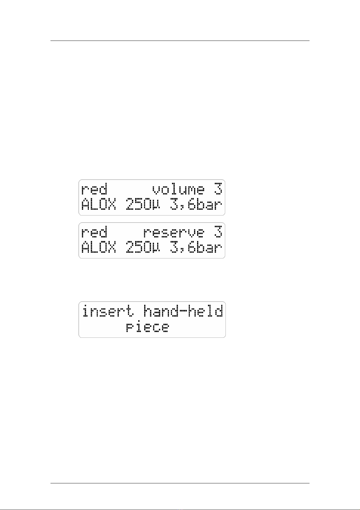
3.11 LED display
(see Fig. 4 page 8 and Fig. 5 page 11)
The following data of the activated blasting system are indicated in the display:
1.
Top left :
Color designation of the blasting system: "white”, "yellow”, "green” or "red”.
2.
Top right :
Volume 0to 9, i.e. 10 selectable steps for blasting agent portion in the
spot blasting jet.
0=minimum
9=maximum
If the reserve filling level has been reached in the blasting agent container,
"Reserve" and "Volume" appear alternating, see 3.9.
3.
Bottom left :
Blasting agent type, e. g. "ALOX”, see 3.9 a page 10.
4.
Bottom
middle
:
Blasting agent grain size µm, see 3.9 b page 10.
5.
Bottom right :
Display of the pressure adjusted in steps of 0.1 bar, see 3.7.
Fig. 5 Display examples
6.
If two or three blasting styluses have been removed from the blasting stylus holder, the
following is displayed:
Fig. 5:Display examples
7.
If all four blasting styluses have been removed from the blasting stylus holders, the desired
blasting systems can be selected with the push buttons (5/...). The same as under 1. to 5.
above is displayed.

12
P-G 400/4 - 18.04.2013 / Vers.: 1
3.12 Changing or cleaning the blasting nozzles
(see Fig. 1 page 4 and Fig. 7 page 14)
Danger Never remove a blasting stylus with or without nozzle through the hand openings from the
blasting chamber, if the unit is connected to the power and compressed air supply and as
long as the blasting agent containers have not been ventilated (see 4.1.1-4)!
Risk of injury, in particular to the eyes!
Removal and integration of the blasting nozzles should be done with the front cover (40)
closed!
Otherwise, in the case of removal and integration thereof with the front cover open:
−set the pre-pressure control (14) to zero (bar) (lift adjustment knob (19) = unlocked) or
interrupt compressed air supply in front of the pre-pressure control (by disconnecting the
quick coupling (62)).
−Ventilate all blasting agent containers by opening the vent screws (8) and
subsequently fastening them again.
1.
Unscrew swivel nut (30) from blasting stylus sleeve (56) and remove blasting nozzle (32).
2.
Insert new blasting nozzle and fasten with swivel nut.
Attention
A rubber sealing ring (35) must be positioned between blasting nozzle (32) and aluminium
hose bushing (33)
Remark If a blasting nozzle is blocked, it should be removed from the unit as described above and
−blown through from the front with compressed air or
−penetrated from the front with a thin wire.
Remark Since, in the case of a blocked nozzle, the blasting agent is sometimes also retained in the
blasting hose, this hose must also be blown through. For this purpose, hold blasting stylus
without nozzle in the direction of the perforated bottom sheet with front cover (40) closed and
activate foot pedal with the unit activated and supplied with compressed air.

P-G 400/4 - 18.04.2013 / Vers.: 1
13
4 Cleaning/Maintenance
4.1 Checking the blasting hoses
(see Fig. 1, 2, 3 and 8 page 4, 5, 6 and 14)
Attention
The blasting hoses are subject to normal wear and tear. They must be checked at least twice
a year.
1.
Switch off the unit with main switch (54) and remove power plug.
2.
Set pre-pressure control (14) to zero (bar) (lift adjustment knob (19) = unlocked), or interrupt
compressed air supply in front of the pre-pressure control (by disconnecting the quick
coupling (62)).
3.
Vent all blasting agent containers by opening the vent screws (8) and subsequently
fastening them again.
4.
Close cover (23).
5.
Remove safety screw (58) for approximately 10mm and swing upper part of the housing to
the back.
6.
Remove spring plug (47) from securing bolt (45).
7.
Extract securing bolt from base (22).
8.
Pull out base (22) downwards from the clamping cylinder housing (46).
9.
Unscrew cover sheet (59).
10.
Remove blasting hose (26) downwards from the clamping cylinder housing (46).
11.
If a blasting hose (26) is damaged in the section, which was inside the clamping cylinder
housing (46) (fabric contours visible on the hose surface), it must be replaced, see section
"4.2".
12.
Insert blasting hose (26) and base (22) into the clamping cylinder housing (46) and fasten
with holding bolt (45).
13.
Slide spring plug (47) into the holding bolt.
Remark The blasting hose must be led straight from adapter sleeve (49) to rubber grommet (34) in
the blasting chamber wall.
14.
Fasten cover sheet (59) again.
15.
Close upper part of housing (57) (Do not squeeze the blasting hoses!) and fasten safety
screw (58) tightly.
16.
Set pre-pressure control to 7 bar and lock adjustment knob again (press downwards) or
reconnect compressed air connection to the pre-pressure control.
14
P-G 400/4 - 18.04.2013 / Vers.: 1
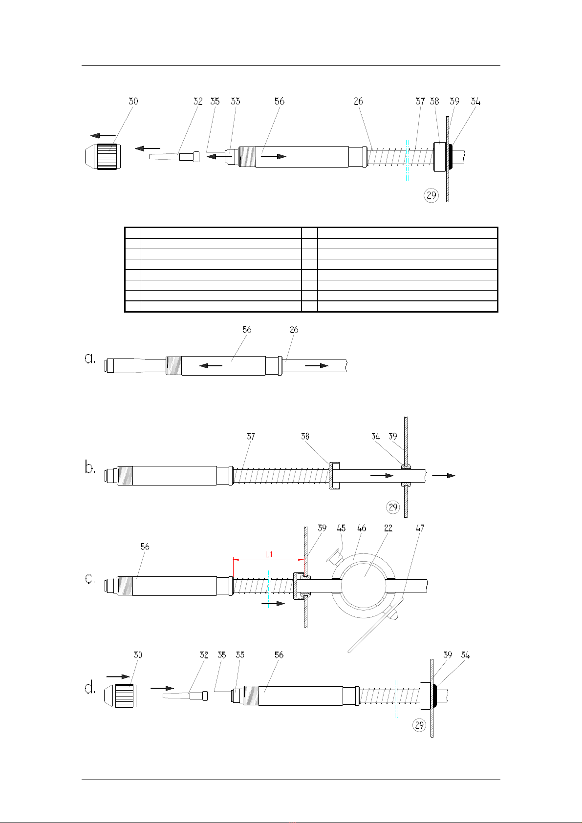
Fig. 7: Disassembly of blasting hose
22
Base 37
Diverting spring
26
Blasting hose 38
Diverting cap
29
Blasting chamber 39
Blasting chamber sheet
30
Swivel nut 45
Holding bolt
32
Blasting nozzle 46
Clamping cylinder housing
33
Hose bushing 47
Spring plug
34
Rubber grommet 56
Blasting stylus sleeve
35
Rubber seal
Fig. 8: Assembly of the blasting hoses

P-G 400/4 - 18.04.2013 / Vers.: 1
15
4.2 Replacing the blasting hoses
(see Fig. 2 page 5 and Fig. 7 and 8 page 14)
For preparing the spot blasting unit for disassembly of the blasting hose see section "4.1",
points 1 to 10.
Removal (old blasting hose):
1.
Remove hose clamp (48) from blasting hose (26).
2.
Remove blasting hose (26) from adapter sleeve (49).
Attention
Check adapter sleeve (49) on this occasion. If its drilling has been enlarged by the blasting
agent flow to such a degree that it has become square-edged on its conical end, the sleeve
must be replaced.
3.
Unscrew cover sheet fastening screw (60) and remove cover sheet (59).
4.
Remove blasting hose from the clamp on the blasting chamber side (29).
5.
Pull out blasting hose (26) from the rubber grommet (34). Remove diverting cap (38) and
diverting spring (37).
6.
Unscrew swivel nut (30) from blasting stylus sleeve (56) and remove blasting nozzle (32).
7.
Grip old blasting hose (26) with a pair of pliers on the hose bushing (33) and pull it from the
front out of the blasting stylus sleeve (56).
Integration (new blasting hose):
Remark Talcum has been applied to the new blasting hose for better slidability. Do not wipe off!
Remark The color of the new blasting hose to be integrated must match with the relevant blasting
system.
8.
Lead new blasting hose (26) through the blasting stylus sleeve (56) see Fig. 8a.
9.
Insert blasting hose tightly into the blasting stylus sleeve, see Fig. 8b.
10.
Slide diverting spring (37) and diverting cap (38) on the blasting hose, as shown in Fig. 8b.
11.
Push blasting hose (from the blasting chamber side (29)) through the rubber grommet (34),
see Fig. 8b.
12.
Press blasting hose with hose clamp (48) attached onto adapter sleeve (49) on mixing
chamber (43) and fasten hose clamp (48), see
Fig. 2
page 5.
13.
Insert blasting hose (26) and base (22) in clamping cylinder housing (46) and fasten with
holding bolt (45).
14.
Slide spring plug (47) in holding bolt (45).
Attention
The blasting hose must be led straight from adapter sleeve (49) to rubber grommet (34) in
the blasting chamber wall!
15.
Fasten cover sheet (59) again.
16.
Insert blasting nozzle (32) and fasten with swivel nut (30), see Fig. 8d.
Attention
The rubber sealing ring (35) must be positioned between blasting nozzle (32) and hose
bushing (33).
17.
Close upper part of housing (57) (Do not squeeze blasting hoses!) and fasten safety screw
(58) tightly.
Attention
The blasting hoses in red and green must be positioned and fastened in the clamp holder in
such a manner that they run approximately 5mm above the perforated sheet bottom in the
blasting chamber. The blasting hoses in white and yellow must be fastened in the clamping
holders in such a manner that no edge or too large arc is formed between rubber grommet
(34) and clamping holder
18.
Set pre-pressure control to 7 bar and lock adjustment knob again (press downwards) or
reconnect compressed air connection with the pre-pressure control.
16
P-G 400/4 - 18.04.2013 / Vers.: 1
4.3 Maintenance
(see Fig. 2 page 5 and Fig. 7 page 14)
The unit requires no further maintenance measures except for changing and controlling the
blasting hoses (26) and the adapter sleeves (49) (see 4.2.1-2 and Attention) and for replacing
the blasting nozzles (32).
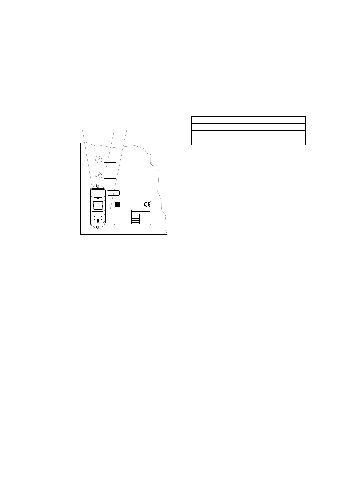
5 Electrical Protection
5 A/T
1 A/T
8 A/T
I
0
5
0
5
1
5
2
5
3
Küferstr.14-16, 73650Winterbach
Harnisch+Rieth
Made inGermany
Maschinen-Typ
Maschinen-Nr.
Baujahr
Spannung
Frequenz
Leistungsaufn.
Luftanschluß
Volt
Herz
Watt
bar/max.
P-G 400
1997
230
50
80
9
Fig. 9: Unit fuses
6 Technical Data
Designation of the unit :Spot blasting unit
Unit type :P-G 400/4
Dimensions :width 490 mm (with plug for foot pedal),
depth 680 mm (with quick coupling),
height 400 mm (with vent screws).
Electrical connection :230 Volt/50 Hz
Over-voltage category :II
Compressed air supply :max. 9 bar
Pre-pressure (operating pressure set
on the pre-pressure control)
:7 bar
Power consumption :approx. 80 Watt
Blasting chamber illumination :1x protected tubular lamp 24 Volt/11Watt
Electrical protection :2x 8 A/T (main fuse)
Electrical protection :1 A/T unit fuse in front of transformator (primary)
Electrical protection :5 A/T unit fuse subsequent to transformator (secondary)
Connection for exhaust system (17) :230 Volt / max. 1000 Watts
Compressed air consumption :max. ca. 80 l/min.
Weight :approx. 45 kg
50
2x unit main fuses 2x 8 A/T
51
Unit fuse in front of transformer 1 A/T
52
Unit fuse subsequent to transformer 5 A/T
53
Power supply plug

7 Warranty conditions
This device conforms with current safety regulations and was subjected to extensive testing before
leaving the works.
We grant a 12 months guarantee in which we are obliged to carry out all repairs necessary as a result
of material or production faults free of charge.
Warranty limitations:
1. The guarantee is considered void if repairs are not carried out by specialized dealers or by us.
2. Spare parts deliveries made for reasons covered by the guarantee do not lead to an extension of the
original guaranty period.
3. Incorrect installation (e.g. failure to heed VDE* regulations or written installation instructions).
4. Incorrect operation or stress.
5. External influences (e.g. transportation damage, damage caused by impacting or blows, damage
caused by the effects of weather or other natural phenomenae).
6. Repairs and alterations not carried out by authorized third parties.
7. Unit breakdown resulting from adjustment, alteration or any other attempt to adapt the unit is not
considered a material or production fault. This guarantee neither encompasses the costs of such
adjustment, alteration or any other attempt to adapt the unit, nor remedying of the resulting
damage.
8. Normal wear and tear (e.g. spray nozzles, hoses, and including hand-held pieces, union nuts, glass
panes, carbon brushes, illumination agents) or damage resulting from incorrect operation is not
covered by the terms of guarantee.
In order to provide you with a comprehensive service we would like you to fill out the guarantee return
form (enclosed at the beginning of these instructions) and send it to us by fax or letter (window
envelope).
* Verband Deutscher Elektrotechniker (German Electrical Technician Association)
Fax no.: 0 71 81/ 73 13 9
-------------------------------------------------------------------------------------------------------------
Fold here for window envelope
----
Copy
Guarantee return form
Maschinenbau
Harnisch+Rieth GmbH & Co.
Postfach 1260
D-73644 Winterbach
Machine
designation::
Spot blasting unit
Machine type:
P-G 400/4
Machine no.:
Date of purchase:
Dealer/Store:
From:
Date/signature:

18
P-G 400/4 - 18.04.2013 / Vers.: 1
8 EC declaration of conformity
In the meaning of the EC Machine Directive 2006/42/EG
We herewith declare that due to its design the machine specified below is in conformity with the basic
safety and health requirements of the EC directives.
In the event of modifications of the machine not approved by us this certificate looses its validity.
Name of the manufacturer :Harnisch+Rieth
Address of the manufacturer :Küferstraße 14-16, 73650 Winterbach
Machine designation :Spot blasting unit
Machine type :P-G 400/4
The following pertinent EC directives were applied:
EC machine directive 2006/42/EG (29.12.2009)
EC low voltage directive 2006/95 EG (29.12.2007)
EMC directive 2004/108/EG (20.07.2007)
Following harmonizing standards were applied:
DIN EN ISO 12100
Safety of Machinery—Part 1, General Principles of Design (04.2004)
DIN EN ISO 14121-
1
Safety of Machinery – Principles of Risk Assessment (12.2007)
DIN EN 61010-1
Safety regulations for measuring, control, regulating, and laboratory devices
DIN EN 60204-1
Safety of machinery - Electrical equipment of machines (06.2007)
DIN EN 61000-6-3
Radio-Suppression of Electrical Equipment –
Radio Interference Voltage / Radio Interference
Power (09.2007)
DIN EN 55 014 :Interference suppression of electrical apparatus and installations.
DIN EN 55 104 :Electromagnetic compatibility, noise resistance requirements (category I).
A technical documentation is available.
The operation instructions belonging to the machine are also available.
Director of the Quality Control Department
Winterbach, 06th September, 1995
Table of contents

