manuals.online logo
Brands
  1. Home
  2. •
  3. Brands
  4. •
  5. Heatmaster
  6. •
  7. Furnace
  8. •
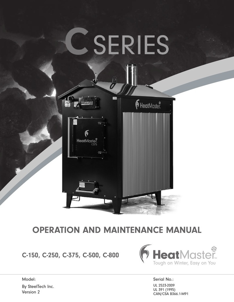
  9. Heatmaster C Series User manual

Heatmaster C Series User manual

Troubleshooting Guide - C Series and MF eSeries
The following are just some of the common scenarios that dealers
and manufacturer’s might encounter when selling outdoor furnaces.
These scenarios have come from our experiences as well as dealer
experiences. The solutions are common things to look for to solve the
problems and are not necessarily the solution to every problem. This
is meant as a helpful guide for these common problems. If anyone has
additional scenarios or information, please submit them.
If the furnace is running but fails to bring water
up to temperature:
1. Checkre.
2. Check fan for operation.
3. Check that the solenoid damper and fanbox elbow is open to
allow air injection.
4. Check to ensure the furnace is sized accurately according to
heat demand.
5. Check fuel type. Poor quality fuel will not provide as many
BTU’s as high quality fuel.
6. Check water level of furnace.
7. Check for ash and creosote blockage at chimney and bypass
trough.
8. Check for blockage in venting and at the rear of the ash
containerwheretheairenterstherebox.
9. Check temperature settings. Make sure high temperature
setting is set to at least 165 F.
10. Check for power at furnace.
11. Check to ensure all pumps in the system are running.
12. Check to make sure there are no leaks, hot/wet spots on your
groundorbreaksinthepipeorttingswhichmaycausethe
pipe to be saturated and lose its insulation value.
13. Check Temperature of water exiting furnace, entering the
building being heated and before and after each heat
exchanger.
If the furnace water is hot but buildings do not
have heat:
1. Check to ensure all pumps in the system are running.
2. Checkltercartridgeforowblockage(ifinstalled).
3. Check for air in the system at the exchanger by bleeding off.
4. Checkforclosedvalvestoensurewaterow.
5. Check Temperature of water exiting furnace, entering the
building being heated and before and after
each heat exchanger.
If the furnace overheats:
1. Check that all doors are closing properly and that door gasket
is completely sealing.
2. Check that the solenoid damper plate is opening and closing
without hang-ups.
3. Check venting and fan box on rear of furnace for air leaks.
4. Check that the temperature settings are correct. The furnace
shouldbesetonHeatingMode(H1)andthehightemperature
setting should be set to no higher than 185 F.
5. Check chimney draft. If the chimney has been extended too far
or has a strong wind blowing over it, it may cause a draft down
the furnace.
6. Check water level.
7. Make sure the door and ash drawer are air tight.
8. Check to ensure all pumps in the system are running.
If the furnace has shut down:
1. Checktoensurethattheunithaspower(doesthelightwork?).
2. Check to ensure the Furnace On/Off switch is in the On
position.
3. Checkthewatertemperature(furnacehasahightemperature
cutoutof190degreesF.andturnsonagainat140degrees).
4. If all checks have not corrected the problem have a technician
check the control panel.
If there is a chimney re:
1. Makesurethereboxandashpandoorsaretightlyclosed.
2. Close all combustion air inlets on the furnace.
If there is a power failure:
1. Openallflow-checkandzonevalvesinthesystem.Depending
on the system design, this may allow convective circulation.
NOTE: This does not apply to gravity systems, as they have no
flow-checkvalvesandwillcontinuetooperatenormallywithout
electricity.
2. It is important to remember that the heating systems cannot
dispose of a great deal of heat without the circulator(s) running.
Avoid over-firing!
DO NOT LOAD LARGE AMOUNTS OF SOLID FUEL INTO
THE FURNACE!
Fire the furnace cautiously until you are able to determine how
quickly the heat system is able to absorb the heat being
produced by the furnace.
3. Whenthepowerhasreturned,resetallow-checkandzone
valves and resume normal operation of the system.
If there is smoke leaking out of the door
Small amounts of smoke leakage is normal due to the fan pressure
and restricted exhaust.
1. Check to ensure door is sealing properly.
2. If the seal is worn out it will have to be replaced.
3. Thedoormayneedtobeadjusted.TodothisloosentheDoor
LatchBearingsandDoorHingebearingsandsetthedoorsoit
seals tightly against the door jamb.
If the furnace has an excessive amount of
creosote either in the rebox or in the bypass
1. Check to ensure the furnace is sized accurately according
to heat demand. If the furnace is oversized it will idle and
causethis.Iftheweatheriswarmormildburnasmallhotre
keeping only enough fuel to last until your next burn time
(generally12hourburntimeisbest).Itwillallowthefurnace
toburnmoreoftenwithgreaterefciencyandhavelessfuel
smouldering during idle, creating less creosote.
2. If the chimney and/or bypass become plugged with creosote it
will be necessary to scrape the creosote out to obtain a proper
burnintherebox.
Having to fill the furnace with water more
thanonce a week or more then a few
gallons of water per week and there is no
obvious explanation
1. Check the temperature settings and gasket on the door and
ash drawer to ensure the furnace is not over temperature
and steaming. If water temperature reaches levels over 200
degrees Fahrenheit the water will steam and water loss will
occur.
2. Check the perimeter of the furnace for water puddles
collecting or dripping from the furnace. If water is found open
thereardoorpanelandsearchtheoortondthesourceof
the water.
3. Check all plumbing in the system to ensure there are no leaks.
The Ranco Temperature control is giving the
user an error message.
Instructions for dealing with Ranco ETC settings and error codes are
included in the owner’s manual on page 16.
Electronic Temperature Control Settings & Specications
Description
TheRancoElectronictemperaturecontrol(ETC)isdesignedto
provide on/off control for heating and cooling. It is equipped with a
liquidcrystaldisplay(LCD)thatprovidesaconstantreadoutofthe
sensed temperature, and a touch keypad that allows the user to easily
and accurately select the set of point temperature, differential and
heating/cooling mode of operation.
Programing steps and display
TheETCcanbeprogrammedinfoursimplestepsusingtheLCD
display and three keys on the face of the control.
STEP 1 To start programming press the SET key once to access the
Fahrenheit/Celsiusmode.TheDisplaywillshowthecurrent
status, either F for degrees Fahrenheit or C for degrees
Celsius. Then press either the up or down arrow key to
toggle between the F or C designation.
STEP 2 Press the SET keyagaintoaccessthesetpoint.TheLCD
will display the current set-point and the S1 indicator will
be blinking on and off to indicate that the control is in the
set point mode. Then press either the up key to increase
or the down key to decrease the set-point to the desired
temperature.
STEP 3 Press the SETkeyagaintoaccessthedifferential.TheLCD
will display the current differential and the DIF1 indicator will
be blinking on and off to indicate that the control is in the
differential mode. Then press the up key to increase or the
down key to decrease the differential to the desired setting.
STEP 4 Press the SET key again to access the cooling or heating
mode.TheLCDwilldisplaythecurrentmode,eitherC1 for
cooling or H1 for heating. Then press either the up or down
key to toggle between the C1 or H1 designation. (This
setting must remain at H1 for proper furnace operation
and temperature regulation.) Press the SET key once more
and programming is complete.
NOTE: The ETC will automatically end programming if no keys are
pressed for thirty seconds. Any settings that have been changed on the
control will be stored at that point.
Step Indicator Description
1 F or C Fahrenheit or Celsius Scale
2 S1 blinking Setpoint Temperature
3 DIF1blinking DifferentialTemperature
4 C1/H1 Cooling or Heating Mode
Troubleshooting Error Messages
DisplayMessage
E1 Appears when either the up or down key is pressed when not in
the programming mode.
To correct: If the E1 message appears even when no keys are
being pressed replace the control.
E2 Appears if the control settings are not properly stored in memory.
To correct: Re-set all settings. If the display continues to show E2,
replace the control.
EP Appears when the probe is open, shorted, or sensing a
temperature that is out of range
To correct: Check to see if the sensed temperature is out of
range. If not, check for probe damage by com paring it to a
known ambient temperature between –30°F and 220°F. Replace
the control if necessary.
EE Appears if the EEPROM data has been corrupted.
To correct:Thisconditioncannotbeeldrepaired.Replacethe
control.
CL Appears if calibration mode has been entered.
To correct:Removepowertothecontrolforatleastve
seconds. Reapply power. If the CL message still appears, replace
the control
Specications
InputVoltage: 120or208/240VAC(24VACoptional),
50/60 Hz
Temperature Range: 30°F to 220°F
DifferentialRange: 1°Fto30°
Sensor: Thermistor,1.94in.Longx.025in.Dia.with
8 ft. cable
Power Consumption: 120/208/240 VAC: 100 Milliamps
24 VAC: 2-6 VA
Electronic Timer Control and Settings
Description
The electronic timer uses the fan to inject air into the
rebox in set intervals. This helps to keep the coal bed
alive during periods of idle. The Timer is factory set to
off and can be programmed to turn on, if necessary.
Different grades of coal will burn differently so it may be
necessary to try some different settings until an optimal
setting is achieved.
Programming the timer
The timer can be set using the two timing dials and
the dip switch settings.
• The Image below shows the timer using the factory settings of
one hour off and one minute on.
• The OFF TIME or yellow side of the timer will control
how long the fan will be off for.
• The ON TIME or black side of the timer will control
how long the fan will be on for.
• Make sure that the 4th DIP switch is ipped up.
This will ensure that the timer will start in an “off”
position.
• Make sure that the 5th DIP switch is turned down.
This will make the control function in an OFF/ON
cycle.
The OFF Timer can be set to run in hours, minutes or
seconds. The rst two DIP switches will control what
the time setting will be.
To set the OFF TIME to hours (recommended)
– The rst DIP switch must be turned down
– The second DIP switch must be turned up
To set the OFF TIME to Minutes
– The rst DIP switch must be turned up
– The second DIP switch must be turned down
To set the OFF TIME to seconds
– Both DIP switches must be turned down
• The 3rd DIP switch controls the timer settings.
If it is set to the X1 or up setting it will count in
1/10 fractions instead of whole hours, minutes or
seconds.
• The 3rd DIP switch must be set to the X10 or in
the down position. This sets the timer in complete
hours, minutes or seconds.
The ON Timer can be set to run in hours, minutes or
seconds. The 6th and 7th DIP switches will control
what the time setting will be.
To set the ON TIME to hours
– The 6th DIP switch must be turned down
– The 7th DIP switch must be turned up
To set the ON TIME to Minutes (recommended)
– The 6th DIP switch must be turned up
– The 7th DIP switch must be turned down
To set the ON TIME to seconds
– Both the 6th and 7th DIP switches must be turned
down
• The 8th DIP switch must be set to the X10 or in
the down position. This sets the timer in complete
hours, minutes or seconds.
• The 8th DIP switch controls the timer settings. If it
is set to the X1 or up setting it will count in 1/10
fractions instead of whole hours, minutes and
seconds.
DIP
SWITCHES
TIME DIAL
FOR FAN
OFF
TIME DIAL
FOR FAN
ON
DIP SWITCH FUNCTION GUIDE

Other manuals for C Series

2

This manual suits for next models

2

Other Heatmaster Furnace manuals

Heatmaster MF Series User manual

Heatmaster

Heatmaster MF Series User manual

Heatmaster MF-3000 User manual

Heatmaster

Heatmaster MF-3000 User manual

Heatmaster G Series User manual

Heatmaster

Heatmaster G Series User manual

Heatmaster B Series User manual

Heatmaster

Heatmaster B Series User manual

Heatmaster G100 User manual

Heatmaster

Heatmaster G100 User manual

Heatmaster C-150 User manual

Heatmaster

Heatmaster C-150 User manual

Heatmaster C Series User manual

Heatmaster

Heatmaster C Series User manual
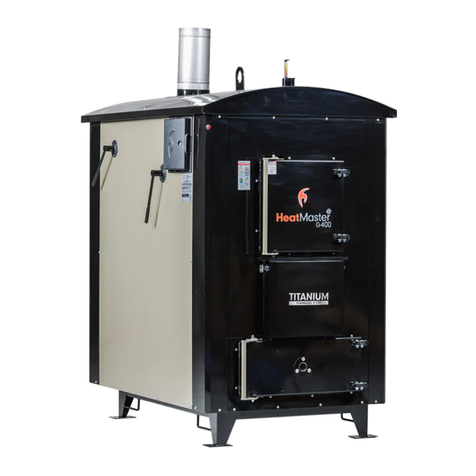
Heatmaster G100 User manual

Heatmaster

Heatmaster G100 User manual
Popular Furnace manuals by other brands
Polar Electro G2 owner's manual

Polar Electro

Polar Electro G2 owner's manual

Haier GE NF80US installation instructions

Haier

Haier GE NF80US installation instructions

Carrier KGANP5201VSP installation instructions

Carrier

Carrier KGANP5201VSP installation instructions

Whirlpool WGGE43 installation instructions

Whirlpool

Whirlpool WGGE43 installation instructions

York Affinity PC9 User's information, maintenance and service manual

York

York Affinity PC9 User's information, maintenance and service manual

HVAC Partners 801S series installation instructions

HVAC Partners

HVAC Partners 801S series installation instructions

Nortek CMF PO Series Service manual

Nortek

Nortek CMF PO Series Service manual

Rinnai RHFE-431FA Specifications

Rinnai

Rinnai RHFE-431FA Specifications

Napoleon 9500-B Series operating instructions

Napoleon

Napoleon 9500-B Series operating instructions

Bryant 345MAV Installation, start-up, and operating instructions

Bryant

Bryant 345MAV Installation, start-up, and operating instructions

Bryant 922SA Installation, start-up, operating and service and maintenance instructions

Bryant

Bryant 922SA Installation, start-up, operating and service and maintenance instructions

Johnson Controls RL18 installation manual

Johnson Controls

Johnson Controls RL18 installation manual

LMF Manufacturing America's Heat AH-100 owner's manual

LMF Manufacturing

LMF Manufacturing America's Heat AH-100 owner's manual

Payne 394G installation instructions

Payne

Payne 394G installation instructions

Payne PG9MTAV Service guide

Payne

Payne PG9MTAV Service guide

Shelter Furnace SF3042 manual

Shelter Furnace

Shelter Furnace SF3042 manual

Trane *UH2B060A9V3VA Installer's guide

Trane

Trane *UH2B060A9V3VA Installer's guide

Lennox ML180DF installation instructions

Lennox

Lennox ML180DF installation instructions

manuals.online logo
manuals.online logoBrands
  • About & Mission
  • Contact us
  • Privacy Policy
  • Terms and Conditions

Copyright 2025 Manuals.Online. All Rights Reserved.