Heinrichs PIT UMF2 User manual

Heinrichs Messtechnik GmbH
OPERATING MANUAL PIT / UMF2B
January 2021
Magnetic-Inductive Flow Velocity Sensor
PIT
UMF2
Operating Manual
Please read the instructions carefully and store them in a save space

Heinrichs Messtechnik GmbH
Page 2 of 23
Operating Manual PIT / UMF2B
Contents
INTRODUCTION.........................................................................................................................................................4
I. Shipping and storage; product inspection................................................................................................................... 4
II. Warranty................................................................................................................................................................................ 4
III. Maintenance, Repair and Hazardous substances..................................................................................................... 4
IV. Disposal ................................................................................................................................................................................. 4
V. Supplementary operating instructions ........................................................................................................................ 4
1STEPS PRIOR TO OPERATION ........................................................................................................................5
2IDENTIFICATION..............................................................................................................................................6
3APPLICATION...................................................................................................................................................7
4MODE OF OPERATION AND SYSTEM DESIGN...............................................................................................8
4.1 Mode of operation .............................................................................................................................................................. 8
4.2 System design ..................................................................................................................................................................... 9
4.2.1 Transmitter mounted on the sensor.............................................................................................................. 9
4.2.2 Remote installation of the transmitter .......................................................................................................10
4.2.3 Sensor versions ..................................................................................................................................................10
5CHARACTERISTICS ....................................................................................................................................... 11
6CONDITIONS OF USE.................................................................................................................................... 12
6.1 Installation conditions .....................................................................................................................................................12
6.1.1 Immersion depth of PIT-*** in the pipe ......................................................................................................12
6.1.2 Removal and installation under process pressure...................................................................................12
6.1.3 Grounding.............................................................................................................................................................13
6.2 Use in hazardous areas...................................................................................................................................................13
6.3 Ambient conditions ..........................................................................................................................................................13
6.4 Medium temperature and pressure............................................................................................................................14
6.4.1 Direct mounted transmitter............................................................................................................................14
6.4.2 Remote mounted transmitter........................................................................................................................14
7DIMENSIONS/WEIGHT ................................................................................................................................ 15
7.1 PIT-UMF2 dimensional drawing for remote transmitter ....................................................................................15
7.2 PIT-** dimensional drawing with direct mounted transmitter UMF2..............................................................16
8POWER SUPPLY / ELECTRICAL CONNECTION ........................................................................................... 17
9SAFETY INFORMATION ............................................................................................................................... 17
9.1 Intended use.......................................................................................................................................................................17
9.2 Installation, start-up and operating personnel........................................................................................................17

Heinrichs Messtechnik GmbH
Operating Manual PIT / UMF2B
Page 3 of 23
10 OPTIONS…………………………………………………………………………..……………………………………………………..18
10.1 Removal and installation under process pressure .................................................................................................18
10.2 PIT (Sensor) Ingress protection IP68 ..........................................................................................................................18
10.2.1 Wiring diagram for remote installation .......................................................................................................19
11 RETURNING THE METER ............................................................................................................................. 20
11.1 Declaration of Decontamination ..................................................................................................................................21
12 DECLARATION OF CONFORMITY ................................................................................................................ 22

Heinrichs Messtechnik GmbH
Page 4 of 23
Operating Manual PIT / UMF2B
Introduction
I. Shipping and storage; product inspection
Shipping and storage
The device is to be safeguarded against dampness, contamination (especially the inside of the flow meter),
impact and damage. Open the packaging with caution to prevent unintentional damage.
Adhere to the temperature limits during storage.
Product inspection
Upon receipt of the product, check the contents of the box and the product particulars against the
information on the delivery slip and order form so as to ensure that all ordered components have been
supplied. Notify us of any shipping damage immediately upon receipt of the product. Any damage claim
received at a later time will not be honoured.
II. Warranty
Your flowmeter was manufactured in accordance with the highest quality standards and was thoroughly
tested prior to shipment. However, in the event any problem arises with your device, we will be happy to
resolve the problem for you as quickly as possible under the terms of the warranty, which can be found in
the terms and conditions of delivery. Your warranty will only be honoured if the device was installed and
operated in accordance with the instructions for your device. Any mounting, commissioning and/or
maintenance work is to be carried out by qualified and authorized technicians only.
III. Maintenance, Repair and Hazardous substances
When used in the intended manner no special maintenance is required. However, the flowmeter should be
checked within the context of routine maintenance of the facility and the pipelines. Should a repair,
calibration or maintenance become necessary, be sure to clean the device thoroughly and follow the steps in
section 11 “Returning the Meter”. before returning the device to Heinrichs Messtechnik.
The operator is liable for any substance removal or personal damage costs arising from inadequate cleaning
of a device sent for repair.
IV. Disposal
Observe the regulations applicable to disposal in the country of installation!
V. Supplementary operating instructions
Supplement operating manuals are available for special features, interfaces and operations relating to your
device, request your copy from our service department.

Heinrichs Messtechnik GmbH
Operating Manual PIT / UMF2B
Page 5 of 23
1Steps prior to operation
It is essential that you read these operating instructions before installing and
operating the device. The device is to be installed and serviced by a qualified
technician only. The UMF2B transmitter is to be used exclusively to measure volume
flow or flow velocity, in conjunction with a Heinrichs Messtechnik EPS, PIT or PITE
sensor.
Downloading of the present document from our web site www.heinrichs.eu and
printing out this document is allowed only for the purposes of using our flowmeters. All rights reserved. No
instructions, wiring diagrams, and/or supplied software, or any portion thereof, may be produced, stored, in
a retrieval system or transmitted by any means, electronic, mechanical, photocopying or otherwise, without
the prior written permission of Heinrichs Messtechnik GmbH.
Although the materials in the present document were prepared with extreme care, errors cannot be ruled
out. Hence, neither the company, the programmer nor the author can be held legally or otherwise
responsible for any erroneous information and/or any loss or damage arising from the use of the
information enclosed.
Heinrichs Messtechnik GmbH extends no express or implied warranty concerning the applicability of the
present document for any purpose other than that described.
We plan to optimize and improve the products described and in so doing will incorporate not only our own
ideas but also, and in particular, any suggestions for improvement made by our customers. If you feel that
there is any way in which our products could be improved, please send your suggestions to the following
address:
Company:
Heinrichs Messtechnik GmbH
HM-EE (R&D Department)
Robert-Perthel-Strasse 9
D-50739 Cologne
Germany
or:
via fax : +49 (221) 49708-178
Note:
We reserve the right to change the technical data in this manual in the light of any
technical progress that might be made.
For updates regarding this product, visit our website at www.heinrichs.eu, where you
will also find contact information for the Heinrichs Messtechnik distributor nearest you.

Heinrichs Messtechnik GmbH
Page 6 of 23
Operating Manual PIT / UMF2B
2Identification
Hersteller:
Heinrichs Messtechnik GmbH
Robert-Perthel-Strasse 9
D-50739 Köln
Deutschland
Produkttyp:
Magnetic –inductive flow sensor based upon Faraday’s law of induction
Produktname:
Sensortyp: PIT
Umformertyp: UMF2B
Dateiname:
pit-umf2b_ba_21.01_en.doc
Version:
21.01, Datum, February 3, 2021

Heinrichs Messtechnik GmbH
Operating Manual PIT / UMF2B
Page 7 of 23
3Application
The magnetic-inductive flow velocity sensor PIT-UMF2 is used to measure or monitor the volume flow of
liquids with and without solids concentration, slurries, pastes and other electrically conductive media while
minimizing pressure drops. The medium must possess a conductivity of at least 20 µS/cm.
Pressure, temperature, density and viscosity do not affect the volume measurements. Smaller portions of
solid particles and small gas bubbles are also measured as part of the volume flow. A larger number of solid
particles or gas bubbles will lead to failures. Special electrodes are available for media that tend to form
greasy films or crusts.
.

Heinrichs Messtechnik GmbH
Page 8 of 23
Operating Manual PIT / UMF2B
4Mode of Operation and System Design
4.1 Mode of operation
It was back in 1832 that Faraday suggested utilizing the principle of electromagnetic induction for
measuring flow velocities. His experiments in the Thames, though unsuccessful due to superimposed
polarization effects, are nonetheless regarded as the first ones in the field of magnetic-inductive flow
measurement.
According to Faraday’s law of electromagnetic induction, an electrical field E is produced in a conductive
liquid moving through a magnetic field B at a velocity v in accordance with the vector product E = [v x B]. A
liquid at flow velocity v and a flow rate Q flows through a meter tube (4), producing a measuring-circuit
voltage Um at the two electrodes (E1 and E2) at right angles to the direction of flow and the magnetic field B
generated by the field coils (3). The size of this measuring-circuit voltage is proportional to the mean flow
velocity and thus the volume flow rate.
Heinrichs Messtechnik GmbH
Operating Manual PIT / UMF2B
Page 9 of 23
4.2 System design
The magnetic-inductive PIT-UMF2 flow measurement system consists of a sensor (PIT), which picks up an
induced measuring signal from the medium flowing through the pipe, and a transmitter (UMF2), which
transforms this signal in standardized output signals (4-20 mA or pulses).
The PIT-*** sensor can be operated with all transmitters for magnetic-inductive flow meters manufactured
by Heinrichs Messtechnik. The sensor is installed (inserted) into the pipe while the transmitter is mounted
directly on top of the sensor or separate remote, depending on the equipment design.
4.2.1 Transmitter mounted on the sensor
This type of construction ensures easy and trouble-free installation
Fitting
Flange
Socket weld
fitting
Sensor
Lining
UMF2B transmitter
housing
Electrodes
Sensor
adapter neck

Heinrichs Messtechnik GmbH
Page 10 of 23
Operating Manual PIT / UMF2B
Junction box
Fitting
Flange
Socket weld fitting
4.2.2 Remote installation of the transmitter
Heinrichs Messtechnik recommends this type of installation when there is little space or the medium
temperatures are high. The sensor and the transmitter are connected by a field coil and an electrode cable.
The electrode cable must be shielded and protected against disturbing interferences.
4.2.2.1 Sensor installation
4.2.2.2 Transmitter mounting
4.2.3 Sensor versions
PIT-S Wetted parts stainless steel / hastelloy / PTFE,
Transmitter neck connection flange stainless steel
PIT-A Wetted parts PFA / hastelloy,
Transmitter neck connection flange stainless steel
PIT-U Version with retraction device
Remote transmitter with terminal connection
box, (For cable length longer than 10 m)
Remote transmitter with direct connected cable
to transmitter, (For cable length of max. 10 m)
(all dimensions in mm)
(all dimensions in mm)

Heinrichs Messtechnik GmbH
Operating Manual PIT / UMF2B
Page 11 of 23
5Characteristics
Accuracy
1.5 % of measured value plus 0.5 % of URV
Conductivity of fluid
20 µS/cm
Influence of ambient temperature
Pulse output 0, 05% pro 10K
Current output 0, 1% pro 10K
Influence of medium temperature
None

Heinrichs Messtechnik GmbH
Page 12 of 23
Operating Manual PIT / UMF2B
6Conditions of use
6.1 Installation conditions
Disturbing elements (e.g. shut-off and control valves) are to be arranged downstream from the sensor. If
this is not possible, flow conditioners must be installed so that no vortexes can reach the pipe section of the
sensor. The mounting location in the pipe system should be selected so that the sensor is continually filled
with the medium. This requirement can be met by using drains and check valves.
In order to stay within the indicated accuracy, the installation must be performed according to EN 29104
"Measurement of Fluid Flow in Closed Conduits –Methods of Evaluating the Performance of Magnetic-
Inductive Flow meters." Based on this standard, the minimum straight run of pipe ahead of the inlet must
be 10 pipe diameters (> 10 x DN) and 5 pipe diameters following the outlet (> 5 x DN) [DN = nominal
diameter of pipe].
In order to prevent serious measuring errors when the pipe is partially filled or when there are gas bubbles
or sediment deposits, the mounting position described above should be chosen.
The limits for the product and ambient temperature must be met at the mounting location. Corrosive
atmospheres must be avoided. Please also take into account the space requirement for a possible removal
of the device.
6.1.1 Immersion depth of PIT-*** in the pipe
In order to suppress the influence of the flow profile as much as possible, the depth of immersion of the
sensor head in the pipe must be 15 % of the inside diameter of the pipe.
The socket weld fitting must not cover the top of the sensor head and must be shortened if necessary.
6.1.2 Removal and installation under process pressure
For easy removal and installation under pressure, a special retraction device is available. When using this
device, the sensor head must not be damaged by closing the valve.
For details, see the Additional Operating Instructions for Removal and Installation the meter under process
pressure Additional Operating Instructions PIT-Druck_BA_0X_eng.doc (see also Section 14 "Options").

Heinrichs Messtechnik GmbH
Operating Manual PIT / UMF2B
Page 13 of 23
6.1.3 Grounding
For safety reasons and to ensure faultless operation of the magnetic-inductive flow meter, earthing of the
flow sensor is important. In accordance with VDE 0100, Part 540, the earthing connections must be
connected to the grounding conductor.
To avoid false measurement, the ground potential must be identical to the ground potential of the medium.
When using insulated and lined pipes or plastic pipes, the metrological grounding of the medium for PIT-S (
SS) is carried out via the wetted part of the sensor head.
All wetted parts of PIT-A ( PFA) are coated with PFA . Therefore it is not possible to ground the medium via
the housing parts. In this case make sure that the PIT-A sensor will be supplied an earthing. If the sensor
does not have an earthing electrode ensure that a suitable earthing disc will be used.
6.2 Use in hazardous areas
The flow meters PIT-…/UMF2 are not intended for use in hazardous areas.
6.3 Ambient conditions
Ambient temperature ranges
-20°C to +60°C, below 0°C the readability of the LCD is limited
Storage temperature
-25°C to +60°C
Climatic category
In accordance with IEC 654-1
Not weather-protected Class D locations exposed directly to open-air climate
Ingress Protection
PIT standard sensor: IP65, option: IP68 / UMF2(b) standard housing IP68 (NEMA 6P)
Caution:
Ingress protection IP68 is only achieved if suitable and tightly screwed down cable glands or
conduits are used. If the cable glands are only tightened manually water may leak into the
terminal compartment in the housing.
Warning:
Particular care must be taken if the window in the housing becomes fogged over or
discolored because moisture, water or product might seep through the wire sheath into the
terminal compartment in the housing!
Caution:
Electromagnetic compatibility is only achieved if the electronics housing is closed. Leaving
the enclosure open can lead to electromagnetic disturbances.
Shock resistance/vibration resistance
The meter should be protected from extreme shocks and vibrations, which could cause damage.

Heinrichs Messtechnik GmbH
Page 14 of 23
Operating Manual PIT / UMF2B
6.4 Medium temperature and pressure
6.4.1 Direct mounted transmitter
Version
Medium temperature
Pressure
PIT-S ( SS / PTFE)
-20°C to 80°C
16 bar
PIT-A ( PFA)
-20°C to 80°C
40 bar
6.4.2 Remote mounted transmitter
Version
Medium temperature
Pressure
PIT-S ( SS / PTFE)
-40°C to100°C
16 bar
PIT-A ( PFA) standard
-40°C to 140°C
40 bar
Heinrichs Messtechnik GmbH
Operating Manual PIT / UMF2B
Page 15 of 23
7Dimensions/weight
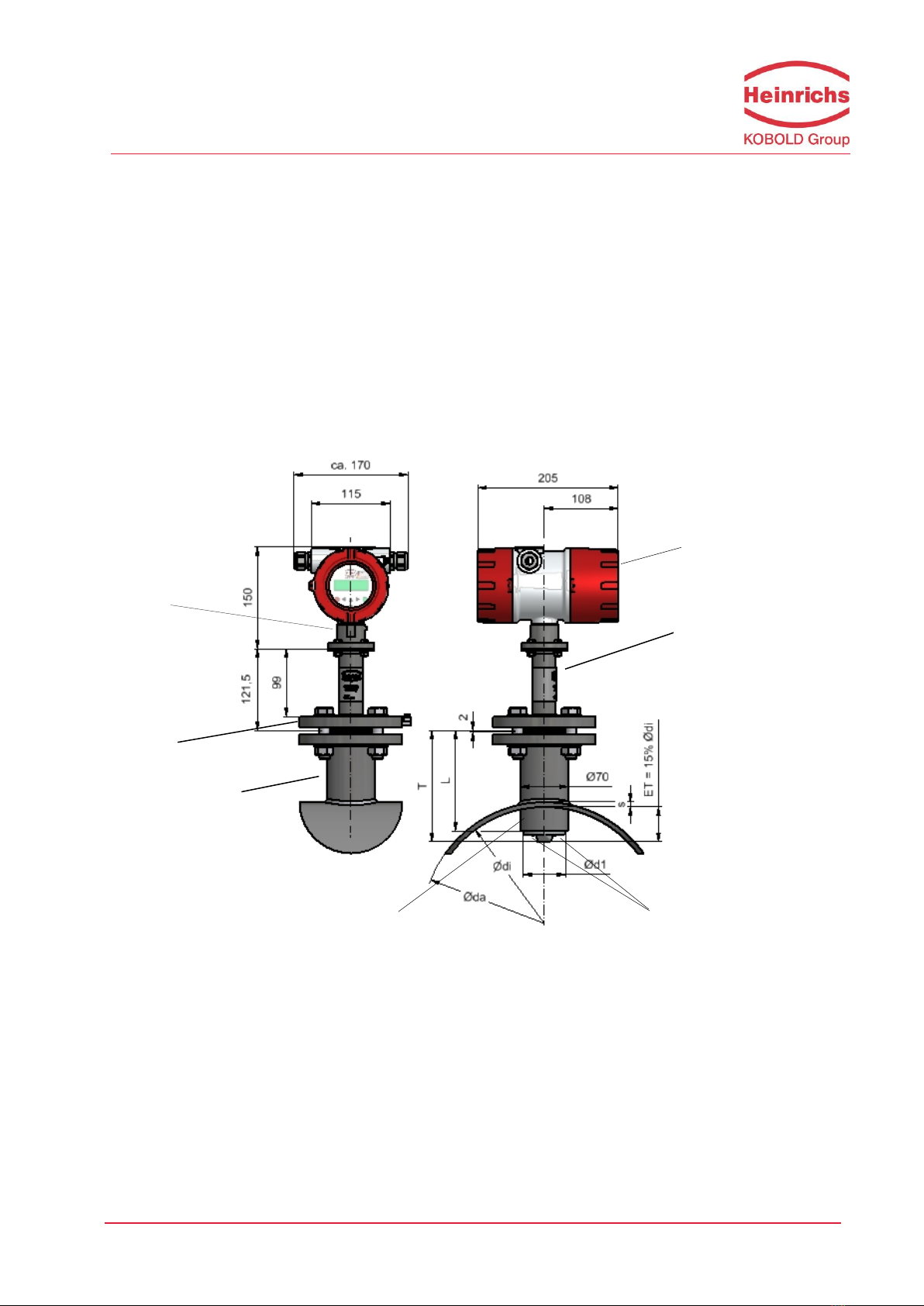
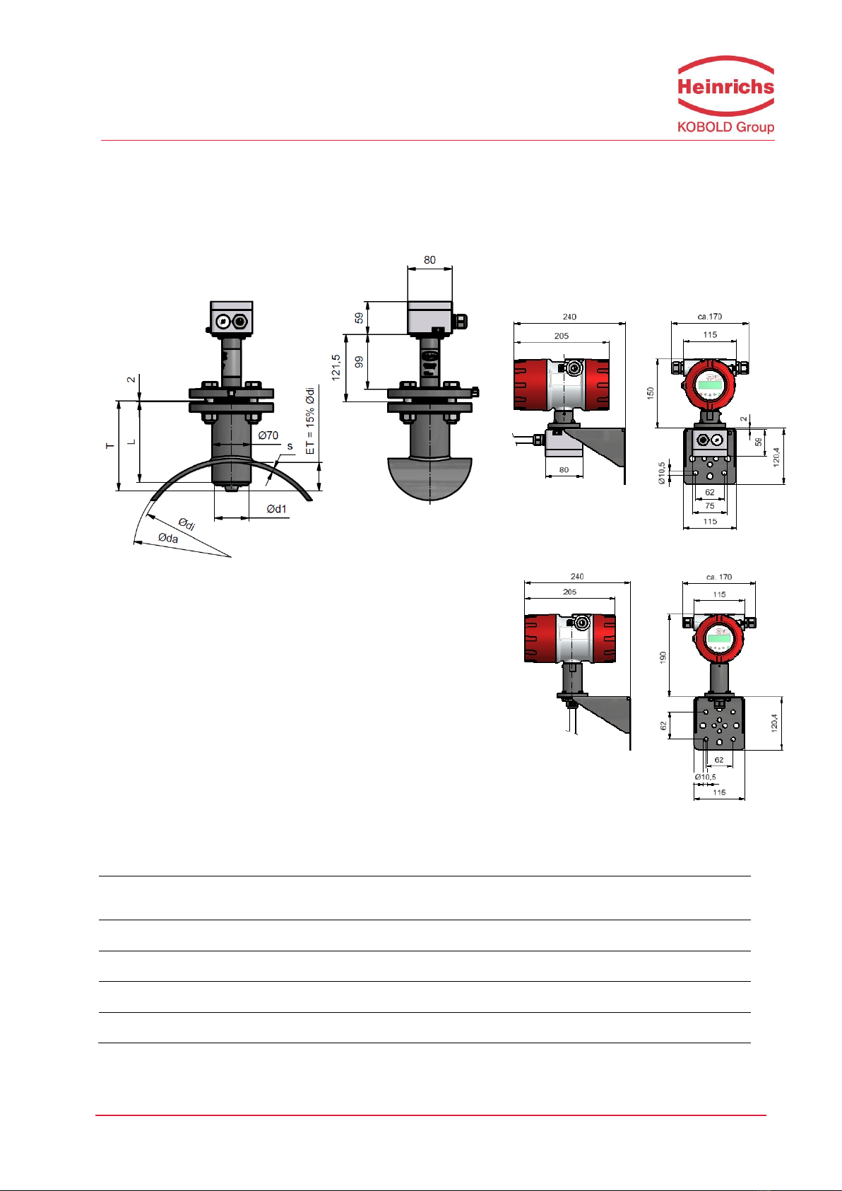
7.1 PIT-UMF2 dimensional drawing for remote transmitter
(all dimensions in mm )
Weight: 3, 6 kg
DN: Nominal Diameter
T: Length of sensor
Ød: Diameter of sensor
L Length of socket weld fitting
ET: Immersion depth in % of pipe diameter
Version
DN
T
Ød1
L
PIT-A (PFA)
150-600
163mm
62mm
145mm
PIT-S ( SS / PTFE))
150-600
163mm
60,3mm
145mm
PIT-S ( SS / PTFE))
700-1200
263mm
60,3mm
170mm
PIT-S ( SS / PTFE))
1400-2000
363mm
60,3mm
170mm
Transmitter with
terminal connection box
Transmitter with directly
connected cable ( up to 10 m)
Heinrichs Messtechnik GmbH
Page 16 of 23
Operating Manual PIT / UMF2B
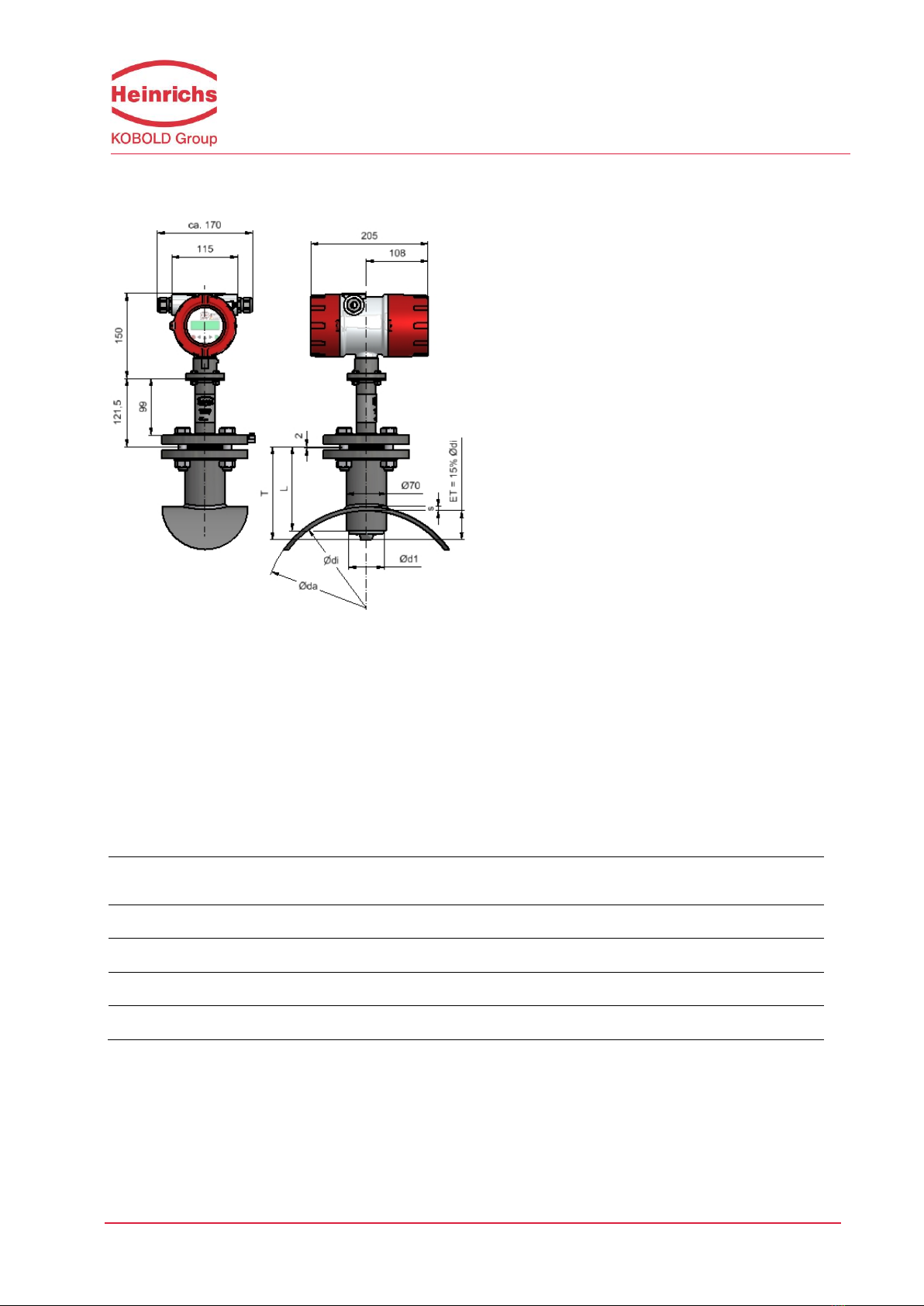
7.2 PIT-** dimensional drawing with direct mounted transmitter UMF2
(all dimensions in mm )
Weight: 5, 5 kg
DN: Nominal Diameter
T: Length of sensor
Ød: Diameter of sensor
L Length of socket weld fitting
Version
DN
T
Ød1
L
PIT-A (PFA)
150-600
163mm
62mm
145mm
PIT-S ( SS / PTFE))
150-600
163mm
60,3mm
145mm
PIT-S ( SS / PTFE))
700-1200
263mm
60,3mm
170mm
PIT-S ( SS / PTFE))
1400-2000
363mm
60,3mm
170mm

Heinrichs Messtechnik GmbH
Operating Manual PIT / UMF2B
Page 17 of 23
8Power supply / electrical connection
See name plate or Operating Instructions of the corresponding transmitter.
9Safety information
9.1 Intended use
The PIT-UMF2 flow meter may be used only for flow measurements of fluids whose conductivity exceeds
20µS/cm. The manufacturer shall not be liable for damages that may result from unintended or
inappropriate use.
When dealing with an aggressive medium, clarify the material durability of all wetted parts.
9.2 Installation, start-up and operating personnel
Only trained specialists authorized by the system operator may carry out the installation, electrical
installations, start-up maintenance and operation. They must read and understand the operating manual
and follow its instructions. Basically, the national conditions and provisions must be followed.
Grundsätzlich sind die in Ihrem Land geltenden Bestimmungen und Vorschriften zu beachten.

Heinrichs Messtechnik GmbH
Page 18 of 23
Operating Manual PIT / UMF2B
10 Options
10.1 Removal and installation under process pressure
In some cases it might be necessary to remove and reinstall the PIT sensor head for cleaning when the pipe
is under process pressure. A special retraction device can be used for this purpose.
When using this device, it is important to ensure that the sensor head will not be damaged by closing the
valve. For a detailed description of this process, see the Additional Operating Instructions (PIT-
Druck_BA_03_eng) for removal and installation the meter under process pressure (Section 5.1.2).
10.2 PIT (Sensor) Ingress protection IP68
A special version of PIT is available with the IP 68 degree of protection. This version is equipped with a
special terminal box, special cable glands and a special cable. The length of the cable must be specified
when placing the order. The terminal box does not need to be opened during the installation. If this should
be necessary, the cover must be remounted carefully. This is the only way to ensure the IP 68 degree of
protection.
The standard immersion depth is 5 m. (Material of terminal box: Aluminum)
optional immersion depth up to 25 m with filling of the terminal box with special “sealing
Compound GHB 1 ” and with factory connected cable at the sensor terminal conn., box.. (Option)
(Material of terminal box: Aluminum)
IP 68 version - seawater resistant: material of terminal box: PE glass-fibre reinforced ,
black 57x75x110 mm (Option)

Heinrichs Messtechnik GmbH
Operating Manual PIT / UMF2B
Page 19 of 23
10.2.1 Wiring diagram for remote installation
The outer shield hast o be connected to the metalized cable glands at both ends. The inner shields are
connected to each other and are plugged into the terminal with the label “Schirm / shield”.
Warning:
Do not connect or disconnect the field coil cable before the mains power of the
transmitter has been disconnected!.
For more details on wiring refer to UMF2B Instruction Manual

Heinrichs Messtechnik GmbH
Page 20 of 23
Operating Manual PIT / UMF2B
11 Returning the Meter
If all attempts to return the device to an operational condition have failed, contact our service department to
arrange the return of your device for repair.
Before sending the device back for repair or servicing, please ensure the following steps have been
performed:
Always enclose a fully completed declaration of decontamination. You will find a template in
section 11.1
Ensure all medium residues have been removed, be sure to clean the seal grooves and recesses
thoroughly.
Provide a description of the encountered problem, providing as much information as possible as
well as a contact person for following correspondence.
Inform us of any special handling requirements you or your processes may have.
Table of contents
Other Heinrichs Accessories manuals


