Hino 600 Instruction manual

FOREWORD
This workshop manual has been prepared to provide information regarding repair procedures on Hino Trucks.
Applicable for HINO 238, 258LP, 268, 338 series, equipped with J08E-VB and J08E-VC engine
When making any repairs on your vehicle, be careful not to be injured through improper procedures.
As for maintenance items, refer to the Driver’s / Owner’s Manual.
All information and specifications in this manual are based upon the latest product information available at the time of printing.
Hino Motors Sales U.S.A., Inc. reserves the right to make changes at any time without prior notice.
Please note that the publications below have also been prepared as relevant workshop manuals for the components and sys-
tems in these vehicles.
Manual Name Pub. No.
Chassis Workshop Manual S1-UNAE11A 2/2
J08E-VB, VC Engine Workshop Manual S5-UJ08E11A
Trouble Shooting Workshop Manual
S7-UNAE11A 1/3
S7-UNAE11A 2/3
S7-UNAE11A 3/3
MENU

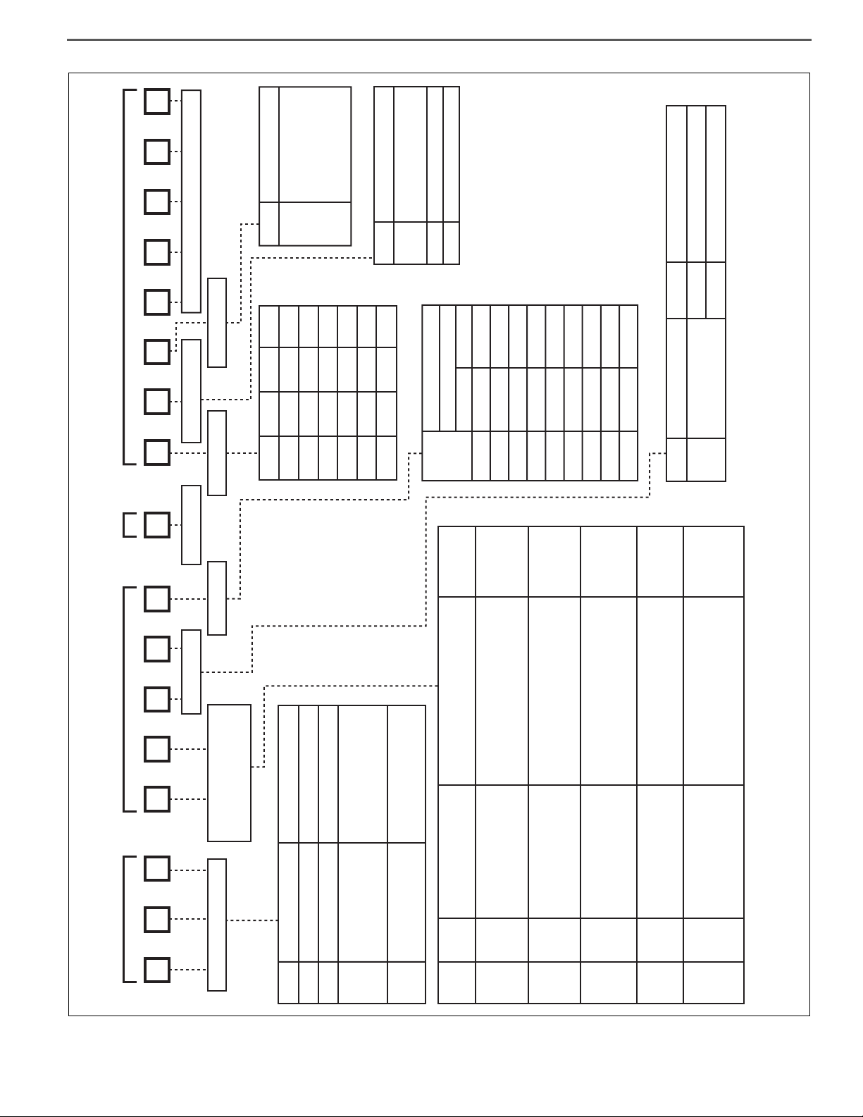
CHAPTER REFERENCES REGARDING THIS WORKSHOP MANUAL
Use this chart to the appropriate chapter numbers for servicing your particular vehicle.
CHAPTER
MANUAL NO. S1-UNAE11A 1/2 (U.S.A.), S1-CNAE11A 1/2 (CANADA)
MODELS HINO 238, 258LP, 268, 338, 358
Production Model
Code NE8J, NF8J, NJ8J, NV8J
GENERAL INTRODUCTION GN02-001
CLUTCH MAIN UNIT CL02-001 CL02-002
CLUTCH CONTROL CL03-001
TRANSMISSION MAIN UNIT TR02-001
AUTOMATIC TRANSMISSION TR04-001 TR04-002
TRANSMISSION/TRANSFER CONTROL
TR06-001 TR06-002
PROPELLER SHAFT PP02-001
DIFFERENTIAL CARRIER DF02-001
BRAKE EQUIPMENT BR01-001 BR01-002
SERVICE BRAKE BR02-001 BR02-002
ABS (ANTI-LOCK BRAKE SYSTEM) BR03-001 BR03-002
EXHAUST BRAKE BR05-001
PARKING BRAKE BR07-001
STEERING EQUIPMENT SR01-001
STEERING UNIT SR02-001
POWER STEERING SR03-001
FRONT AXLE AX02-001
REAR AXLE AX03-001
WHEEL & TIRE AX04-001
SUSPENSION SU02-001
CHASSIS FRAME FC02-001
CAB CA02-001
ELECTRICAL EQUIPMENT EL01-001
ELECTRIC WIRE EL02-001
This manual does not contain items on half-tone dot meshing.

CLUTCH EQUIPMENT
CLUTCH MAIN UNIT
CLUTCH CONTROL
TRANSMISSION EQUIPMENT
TRANSMISSION MAIN UNIT
TRANSFER MAIN UNIT
AUTOMATIC TRANSMISSION
PTO (POWER TAKE-OFF)
TRANSMISSION / TRANSFER CONTROL
PROPELLER SHAFT
DIFFERENTIAL EQUIPMENT
DIFFERENTIAL CARRIER
INDEX: CHASSIS GROUP 1/4
PROPELLER SHAFT EQUIPMENT
BRAKE EQUIPMENT
SERVICE BRAKE
ABS
GENERAL INTRODUCTION
WORKSHOP
MANUAL

CAB EQUIPMENT
CAB
INDEX: CHASSIS GROUP 3/4
ELECTRICAL EQUIPMENT
ELECTRIC WIRE
HYBRID SYSTEM

ENGINE CONTROL
FUEL CONTROL
BRAKE CONTROL
SUSPENSION CONTROL
CAB EQUIPMENT CONTROL
OTHERS
INDEX: CHASSIS GROUP 4/4

GENERAL INTRODUCTION (CHASSIS) GN02–1
GN 0 2
GENERAL INTRODUCTION (CHASSIS) GN02-001
GENERAL INTRODUCTION.....................GN02-2
GENERAL PRECAUTIONS.............................GN02-2
IDENTIFICATION INFORMATION ...................GN02-5
HOW TO USE
THIS WORKSHOP MANUAL.........................GN02-12
PRECAUTIONS .............................................GN02-15
SEALANT ON THE TAPERED SCREW
FOR PIPING ..................................................GN02-18
NYLON TUBE REPLACEMENT METHOD ...GN02-19
METRIC INFORMATION ...............................GN02-21
SPECIFIED TORQUE
FOR STANDARD BOLTS AND NUTS ...........GN02-23
SPECIFIED TORQUE
FOR FLANGE BOLTS AND NUTS ................GN02-23
RECOMMENDED LUBRICANTS ..................GN02-25
VEHICLE LIFT
AND SUPPORT LOCATIONS........................GN02-27
INFORMATION DISPLAY ..............................GN02-29
SYMPTOM SIMULATION ..............................GN02-34
GLOSSARY ...................................................GN02-36
GLOSSARY OF SAE AND HINO TERMS.....GN02-39

GENERAL INTRODUCTION (CHASSIS)GN02–2
GENERAL INTRODUCTION
GENERAL PRECAUTIONS
EN00Z00020100001
Some recommended and standard maintenance services for your vehicle are included in this section. When performing main-
tenance on your vehicle be careful not to get injured by improper work. Improper or incomplete work can cause a malfunction
of the vehicle which may result in personal injury and/or property damage. If you have any question about performing mainte-
nance, please consult your Hino dealer.
DEFINITION OF SAFETY TERMS
WARNING
When working on your vehicle, observe the following general precautions to prevent death, personal injury and/or
property damage in addition to the particular DANGERS, WARNINGS, CAUTIONS and NOTICES in each chapter.
•Always wear safety glasses or goggles to protect your eyes.
•Remove rings, watches, ties, loose hanging jewelry and loose clothing before starting work on the vehicle.
•Bind long hair securely behind the head.
•When working on the vehicle, apply the parking brake firmly, place the gear shift lever in "Neutral" or "N" and
block the wheels.
•Always turn off the starter switch to stop the engine, unless the operation requires the engine running. Remov-
ing the key from the switch is recommended.
•To avoid serious burns, keep yourself away from hot metal parts such as the engine, exhaust manifold, radia-
tor, muffler, exhaust pipe and tail pipe.
•Do not smoke while working on the vehicle since fuel, and gas from battery are flammable.
•Take utmost care when working on the battery. It contains corrosive sulfuric acid.
•Large electric current flows through the battery cable and starter cable. Be careful not to cause a short which
can result in personal injury and/or property damage.
•Read carefully and observe the instructions specified on the jack before using it.
•Use safety stands to support the vehicle whenever you need to work under it. It is dangerous to work under a
vehicle supported only by a jack.
•If it is necessary to run the engine after the hood is raised (tilted), make sure that the parking brake is firmly
applied, the wheels are blocked, and the gear shift lever is positioned in "Neutral" before staring the engine.
•Run the engine only in a well-ventilated area to avoid inhalation of carbon monoxide.
•Keep yourself, your clothing and your tools away from moving parts such as the cooling fan and V-belts when
the engine is running.
•Be careful not to damage lines and hoses by stepping or holding your feet on them.
•Be careful not to leave any tool in the engine compartment. The tool may be hit by moving parts, which can
cause personal injury.
Indicates an extremely hazardous situation if proper procedures are not followed and could
result in death or serious injury.
Indicates a potential hazardous situation if proper procedures are not followed and could
result in death or serious injury.
Indicates a hazardous situation if proper procedures are not followed and could result in
serious injury or damage to parts/equipment.
Indicates the need to follow proper procedures and to pay attention to precautions so that
efficient service is provided.
Provides additional information to help you to perform the repair efficiently.

GENERAL INTRODUCTION (CHASSIS) GN02–3
TOWING
•When being towed, always place the gear shift lever in "Neutral" and release the parking brake completely. In order to
protect the bumper, fit a protection bar against the lower edge of the bumper and put a wood block under the frame near
the No. 1 cross member when attaching the towing chain. Never lift or tow the vehicle if the chain is in direct contact with
the bumper.
1. Towing procedures
(1) Make sure that the propeller shaft of the vehicle to be towed is removed. When the differential gear or rear axle shaft is
defective, remove both right and left rear axle shafts, then cover the hub opening to prevent loss of axle lubricant and
entry of dirt or foreign matter.
(2) Use a heavy duty cable or rope when towing the vehicle. Fasten the cable securely to the towing hook on the frame.
(3) The angle of pulling direction of the cable fastened to the towing hook must not exceed 15in horizontal and vertical
directions from the straight ahead, level direction. Avoid using the hook in a way that subjects it to jerk, as in towing a
vehicle trapped in a gutter.
(4) Keep the gear shift lever in Neutral.
(5) Make sure that the starter switch is kept in the "ON" position, if the engine is not running.
(6) Make sure that the engine of the towed vehicle is kept running. If the engine is off, no compressed air/ no vacuum will be
available for the brake. This is dangerous, as the brake system does not function if the engine is not running.
In addition, the power steering system will not function. The steering wheel, therefore, will become unusually hard to turn,
making it impossible to control the vehicle.
(7) Note that the engine brake and exhaust brake cannot be applied, if the propeller shaft is removed.
(8) Make a slow start to minimize shock. Towing speed should be less than 30 km/h {18 mile/h}.
2. If the engine of the towed vehicle is defective, make sure that the vehicle is towed only by a tow truck designed
for that purpose.
(1) Front end towing (with front wheels raised off the ground)
When towing from the front end with the front wheels raised off the ground, remove the rear axle shafts to protect the
transmission and differential gears from being damaged. The hub openings should be covered to prevent the loss of axle
lubricant or the entry of dirt or foreign matter. The above-mentioned precautions should be observed for vehicles
equipped with either manual or automatic transmission, and for even short distance towing. After being towed, check and
refill the rear axle housing with lubricant if necessary.
(2) Rear end towing
When being towed with the rear wheels raised off the ground, fasten and secure the steering wheel in a straight-ahead
position.
CLEAN AIR ACT
1. Heavy-duty engine rebuilding practices.
§ 86.004-40
•The provisions of this section are applicable to heavy-duty engines subject to model year 2004 or later standards and are
applicable to the process of engine rebuilding (or rebuilding a portion of an engine or engine system). The process of
engine rebuilding generally includes disassembly, replacement of multiple parts due to wear, and reassembly, and also
may include the removal of the engine from the vehicle and other acts associated with rebuilding an engine. Any deviation
from the provisions contained in this section is a prohibited act under section 203(a) (3) of the Clean Air Act (42 U.S.C.
7522(a) (3)).
(1) When rebuilding an engine, portions of an engine, or an engine system, there must be a reasonable technical basis for
knowing that the resultant engine is equivalent, from an emissions standpoint, to a certified configuration (i.e., tolerances,
calibrations, specifications) and the model year(s) of the resulting engine configuration must be identified. A reasonable
basis would exist if:
a. Parts installed, whether the parts are new, used, or rebuilt, are such that a person familiar with the design and func-
tion of motor vehicle engines would reasonably believe that the parts perform the same function with respect to emis-
sions control as the original parts; and
b. Any parameter adjustment or design element change is made only:
In accordance with the original engine manufacturer's instructions; or
Where data or other reasonable technical basis exists that such parameter adjustment or design element change,
when performed on the engine or similar engines, is not expected to adversely affect in-use emissions.
(2) When an engine is being rebuilt and remains installed or is reinstalled in the same vehicle, it must be rebuilt to a configu-
ration of the same or later model year as the original engine. When an engine is being replaced, the replacement engine
must be an engine of (or rebuilt to) a configuration of the same or later model year as the original engine.

GENERAL INTRODUCTION (CHASSIS)GN02–4
(3) At time of rebuild, emissions-related codes or signals from on-board monitoring systems may not be erased or reset with-
out diagnosing and responding appropriately to the diagnostic codes, regardless of whether the systems are installed to
satisfy requirements in § 86.004-25 or for other reasons and regardless of form or interface. Diagnostic systems must be
free of all such codes when the rebuilt engine is returned to service. Such signals may not be rendered inoperative during
the rebuilding process.
(4) When conducting a rebuild without removing the engine from the vehicle, or during the installation of a rebuilt engine, all
critical emissions-related components listed in § 86.004-25(2) not otherwise addressed by paragraphs (1) through (3) of
this section must be checked and cleaned, adjusted, repaired, or replaced as necessary, following manufacturer recom-
mended practices.
(5) Records shall be kept by parties conducting activities included in paragraphs (1) through (4) of this section. The records
shall include at minimum the mileage and/or hours at time of rebuild, a listing of work performed on the engine and emis-
sions-related control components including a listing of parts and components used, engine parameter adjustments, emis-
sions-related codes or signals responded to and reset, and work performed under paragraph (4) of this section.
a. Parties may keep records in whatever format or system they choose as long as the records are understandable to an
EPA enforcement officer or can be otherwise provided to an EPA enforcement officer in an understandable format
when requested.
b. Parties are not required to keep records of information that is not reasonably available through normal business prac-
tices including information on activities not conducted by themselves or information that they cannot reasonably
access.
c. Parties may keep records of their rebuilding practices for an engine family rather than on each individual engine
rebuilt in cases where those rebuild practices are followed routinely.
d. Records must be kept for a minimum of two years after the engine is rebuilt.
2. Maintenance instructions.
§ 86.010-38
(1) For each new diesel-fueled engine subject to the standards prescribed in § 86.007-11, as applicable, the manufacturer
shall furnish or cause to be furnished to the ultimate purchaser a statement that
"This engine must be operated only with ultra low-sulfur diesel fuel (meeting EPA specifications for highway die-
sel fuel, including a 15 ppm sulfur cap)."

GENERAL INTRODUCTION (CHASSIS) GN02–5
IDENTIFICATION INFORMATION
EN00Z00020200001
1. VEHICLE IDENTIFICATION NUMBER
•VEHICLE IDENTIFICATION NUMBER (VIN) is comprised of 17 digits and letters. The VIN label is affixed to the left pillar
of the cab.
These numbers are used for identification purposes when you have a vehicle registered or inspected. Please quote these
numbers when ordering spare parts or reporting technical matter to receive prompt service attention.
•The following is an explanation of the items that are listed on the VIN label.
VIN
label

GENERAL INTRODUCTION (CHASSIS)GN02–6
(1) VIN
See VEHICLE IDENTIFICATION NUMBER (VIN) STRUCTURE on the following page.
(2) P.S. (PRODUCTION SERIES) AND VEHICLE COMPONENTS
MODEL
(CLASS)
PRODUC-
TION CODE CLUTCH
SIZE
TRANS-
MIS-
SION
SERIES
TRANSMISSION RATIO REAR
AXLE
SERIES
SER-
VICE
BRAKE
PARK-
ING
BRAKE
SUSPEN-
SION
MODEL SERIES 1st 2nd 3rd 4th 5th 6th Rev.
HINO238
(6) NE8J HBC -
2200HS 3.10 1.81 1.41 1.00 0.71 0.61 4.49
RS17-145
HD
L
or
A
RS19-145
2200RDS 3.10 1.81 1.41 1.00 0.71 0.61 4.49
RS17-145
RS19-145
2500RDS 3.51 1.90 1.44 1.00 0.74 0.64 5.09
RS17-145
RS19-145
HINO258
(6)
NE8J
GBC 350mm FS5406 9.01 5.27 3.22 2.04 1.36 1.00 8.63
RS17-145
HD
L
or
A
RS19-145
HBC
- 2200HS 3.10 1.81 1.41 1.00 0.71 0.61 4.49
RS17-145
RS19-145
- 2200RDS 3.10 1.81 1.41 1.00 0.71 0.61 4.49
RS17-145
RS19-145
- 2500RDS 3.51 1.90 1.44 1.00 0.74 0.64 5.09
RS17-145
RS19-145
NJ8J
JBC 350mm FS5406 9.01 5.27 3.22 2.04 1.36 1.00 8.63
RS17-145
FWA
RS19-145
KBC
- 2200HS 3.10 1.81 1.41 1.00 0.71 0.61 4.49
RS17-145
FW
L
or
A
RS19-145
- 2200RDS 3.10 1.81 1.41 1.00 0.71 0.61 4.49
RS17-145
RS19-145
- 2500RDS 3.51 1.90 1.44 1.00 0.74 0.64 5.09
RS17-145
RS19-145
HINO268
(6) NE8J
GBC 350mm FS5406 9.01 5.27 3.22 2.04 1.36 1.00 8.63
RS17-145
HD
L
or
A
RS19-145
HBC
- 2200HS 3.10 1.81 1.41 1.00 0.71 0.61 4.49
RS17-145
RS19-145
- 2200RDS 3.10 1.81 1.41 1.00 0.71 0.61 4.49
RS17-145
RS19-145
- 2500RDS 3.51 1.90 1.44 1.00 0.74 0.64 5.09
RS17-145
RS19-145

GENERAL INTRODUCTION (CHASSIS) GN02–7
HINO268
(6) NJ8J
JBC 350mm FS5406 9.01 5.27 3.22 2.04 1.36 1.00 8.63
RS17-145
FWL
or
A
RS19-145
KBC
- 2200HS 3.10 1.81 1.41 1.00 0.71 0.61 4.49
RS17-145
RS19-145
- 2200RDS 3.10 1.81 1.41 1.00 0.71 0.61 4.49
RS17-145
RS19-145
- 2500RDS 3.51 1.90 1.44 1.00 0.74 0.64 5.09
RS17-145
RS19-145
HINO268
(7)
NV8J
NBC 350mm FS6406 9.01 5.27 3.22 2.04 1.36 1.00 8.63
RS21-145
RS23-160
PBC
- 2500RDS 3.51 1.90 1.44 1.00 0.74 0.64 5.09
RS21-145
FW
L
or
A
RS23-160
- 3000RDS 3.49 1.86 1.41 1.00 0.75 0.65 5.03
RS21-145
RS23-160
- 3500RDS 4.59 2.25 1.54 1.00 0.75 0.65 5.00
RS21-145
RS23-160
TBC 350mm FS6406 9.01 5.27 3.22 2.04 1.36 1.00 8.63
RS21-145
RS23-160
SBC
- 2500RDS 3.51 1.90 1.44 1.00 0.74 0.64 5.09
RS21-145
RS23-160
- 3000RDS 3.49 1.86 1.41 1.00 0.75 0.65 5.03
RS21-145
RS23-160
- 3500RDS 4.59 2.25 1.54 1.00 0.75 0.65 5.00
RS21-145
RS23-160
HINO338
(7)
NF8J
DBC 350mm FS6406 9.01 5.27 3.22 2.04 1.36 1.00 8.63 RS21-145
HDL
or
A
EBC - 2500RDS 3.51 1.90 1.44 1.00 0.74 0.64 5.09 RS21-145
NV8J NBC 350mm FS6406 9.01 5.27 3.22 2.04 1.36 1.00 8.63
RS21-145
FW
RS23-160
MODEL
(CLASS)
PRODUC-
TION CODE CLUTCH
SIZE
TRANS-
MIS-
SION
SERIES
TRANSMISSION RATIO REAR
AXLE
SERIES
SER-
VICE
BRAKE
PARK-
ING
BRAKE
SUSPEN-
SION
MODEL SERIES 1st 2nd 3rd 4th 5th 6th Rev.

GENERAL INTRODUCTION (CHASSIS)GN02–8
HINO338
(7) NV8J
PBC
- 2500RDS 3.51 1.90 1.44 1.00 0.74 0.64 5.09
RS21-145
FW
L
or
A
RS23-160
- 3000RDS 3.49 1.86 1.41 1.00 0.75 0.65 5.03
RS21-145
RS23-160
- 3500RDS 4.59 2.25 1.54 1.00 0.75 0.65 5.00
RS21-145
RS23-160
TBC 350mm FS6406 9.01 5.27 3.22 2.04 1.36 1.00 8.63
RS21-145
RS23-160
SBC
- 2500RDS 3.51 1.90 1.44 1.00 0.74 0.64 5.09
RS21-145
RS23-160
- 3000RDS 3.49 1.86 1.41 1.00 0.75 0.65 5.03
RS21-145
RS23-160
- 3500RDS 4.59 2.25 1.54 1.00 0.75 0.65 5.00
RS21-145
RS23-160
HINO358
(8)
NH8J
NBC 350mm FS6406 9.01 5.27 3.22 2.04 1.36 1.00 8.63 RS23-160
FW
L
or
A
PBC
- 3000RDS 3.49 1.86 1.41 1.00 0.75 0.65 5.03 RS23-160
- 3500RDS 4.59 2.25 1.54 1.00 0.75 0.65 5.00 RS23-160
TBC 350mm FS6406 9.01 5.27 3.22 2.04 1.36 1.00 8.63 RS23-160
SBC
- 3000RDS 3.49 1.86 1.41 1.00 0.75 0.65 5.03 RS23-160
FW
L
or
A
- 3500RDS 4.59 2.25 1.54 1.00 0.75 0.65 5.00 RS23-160
CODE SERVICE BRAKE
H: Hydraulic
F: Full air
PARKING BRAKE CONTROL CODE
D: ACTING ON DIFFERENTIAL
W: ACTING ON REAR WHEEL
SUSPENSION
L: LEAF
A: AIR
MODEL
(CLASS)
PRODUC-
TION CODE CLUTCH
SIZE
TRANS-
MIS-
SION
SERIES
TRANSMISSION RATIO REAR
AXLE
SERIES
SER-
VICE
BRAKE
PARK-
ING
BRAKE
SUSPEN-
SION
MODEL SERIES 1st 2nd 3rd 4th 5th 6th Rev.
GENERAL INTRODUCTION (CHASSIS) GN02–9
HINO VEHICLE IDENTIFICATION NUMBER (VIN) STRUCTURE FOR U.S.A. and CANADA (2015MY)
WMI VDS CD VIS
12 3 4 56 78 9 10111213141516
5P V N J 8 J T 4 F 4 S1 0 0 0
17
1
MANUFACTURER TYPE MAKE, MODEL
LINE & CAB/BODY TYPE,
SERIES, BRAKE SYSTEM
MODEL YEAR
ASSEMBLY PLANT
ENGINE MODEL
WHEEL BASE
CHECK DIGIT
MODIFICATION
SEQUENTIAL NUMBER
CODE
JHA
JHB
TRUCK
INCOMPLETE VEHICLE
TYPEMANUFACTURER
HINO MOTORS, LTD.
HINO MOTORS, LTD.
5PV INCOMPLETE VEHICLE
HINO MOTORS
MANUFACTURING
U.S.A., INC.
2AY INCOMPLETE VEHICLE
HINO MOTORS
CANADA, LTD.
CODE
P
CODE
2023
YEARYEAR
R 2024
S 2025
T 2026L 2020
M 2021
N 2022
H 2017
J 2018
K 2019
F 2015
G 2016
CODE
8J J08E-VC
MODEL
7.6 LITERS, DIESEL 220HP
J08E-VB 7.6 LITERS, DIESEL 260HP
DESCRIPTIONMANUFACTURER
HINO MOTORS, LTD.
CODE
G 3,861
LENGTH
NE - NV
mm in.
J4,445
L4,750
M5,207
N5,385
P5,512
R5,969
T6,426
V6,883
152
175
187
205
212
217
235
253
271
CODE
S
DESCRIPTION
A NEW LETTER
T WILL BE ALLOTTED
U AT EVERY MAJOR
... MODIFICATION
Z
CODE
1
ASSEMBLY PLANT
HINO MOTORS, LTD.
HINO PLANT IN JAPAN
3 Canada Plant
4 W.V Plant
MODEL
CODE
MAKE
NF HYDRAULIC
LINE & CAB/BODY TYPE
INCOMPLETE VEHICLE
Intended GVWR and Vehicle Class
and Class
BRAKE
SYSTEMS
NV
FULL AIR
FULL AIR
INCOMPLETE VEHICLE
INCOMPLETE VEHICLE
INCOMPLETE VEHICLE
INCOMPLETE VEHICLE
NJ 10434 kg. - 11793 kg or less
[23,001 - 26,000 (lbs.)] (CLASS 6)
13609 kg. - 14968 kg or less
[30,001 - 33,000 (lbs.)] (CLASS 7)
13609 kg. - 14968 kg or less
[30,001 - 33,000 (lbs.)] (CLASS 7)
14969 kg - 15875 kg or less
[33,001 - 35,000 (lbs.) ] (CLASS 8)
NE
HINO
HINO
NHHINO
HINO
HINO 8846 kg. - 11793 kg or less
[19,501 - 26,000 (lbs.)] (CLASS 6) HYDRAULIC
FULL AIR
SHTS00Z000200007

GENERAL INTRODUCTION (CHASSIS)GN02–10
2. VEHICLE NOISE EMISSION CONTROL INFORMATION
•The Vehicle Noise Emission Control Information is affixed to the side
of the left door. The name of manufacturer, production year and
month, and noise emission applicable to medium and heavy trucks in
conformity with U.S. EPA Regulations are displayed.
3. ENGINE SERIAL NUMBERS.
•Please quote these numbers when ordering spare parts or reporting
technical matter to receive prompt service attention.
The engine serial number is engraved on the engine cylinder block.
4. CHASSIS SERIAL NUMBER
•Chassis serial number is engraved on the left side frame near the
front wheel.
5. CLEAN IDLE CERTIFIED LABEL FOR U.S.
•Make sure that the following clean engine idling certified label is
affixed to the outside of the left door.
By the CARB below, the label must be affixed there to prove that the
new vehicle with diesel engine manufactured from Jan., 2008 con-
forms to this low.
VEHICLE NOISE EMISSION CONTROL INFORMATION
THIS VEHICLE CONFORMS TO U.S. EPA REGULATIONS FOR NOISE
EMISSION APPLICABLE TO MEDIUM AND HEAVY TRUCKS.
THE FOLLOWING ACTS OR THE CAUSING THEREOF BY ANY PERSON ARE
PROHIBITED BY THE NOISE CONTROL ACT OF 1972.
(A)THE REMOVAL OR RENDERING INOPERATIVE. OTHER THAN FOR
PURPOSES OF MAINTENANCE, REPAIR, OR REPLACEMENT, OF ANY
NOISE CONTROL DEVICE OR ELEMENT OF DESIGN (LISTED IN THE
OWNER' S MANUAL) INCORPORATED INTO THIS VEHICLE IN
COMPLIANCE WITH THE NOISE CONTROL ACT.
(B)THE USE OF THIS VEHICLE AFTER SUCH DEVICE OR ELEMENT OF
DESIGN HAS BEEN REMOVED OR RENDERED INOPERATIVE.
MFD BY:HINO MOTORS, LTD. DATE OF MANUFACTURE 03/2009
For all models
SHTS00Z000200010
SHTS00Z000200011
SHTS00Z000200012
SHTS00Z000200013-C
CARB § 1956.8. Exhaust Emission Standard and Test Procedure
(a) (b) Heavy-Duty Diesel Engine Idling Requirements

GENERAL INTRODUCTION (CHASSIS) GN02–11
6. VEHICLE EMISSION CONTROL INFORMATION
•The Vehicle Emission Control Information is affixed to the side of the
left door. The name of manufacturer, production year and month, and
emission applicable to medium and heavy trucks in conformity with
U.S. EPA Regulations are displayed.
VIN
label
Vehicle emission
control information
GN02-13-1-0
For example
GN02-13-1-1

GENERAL INTRODUCTION (CHASSIS)GN02–12
HOW TO USE THIS WORKSHOP MANUAL
EN00Z00020200002
This workshop manual is designed as a guide for servicing the vehicle.
An INDEX is provided on the first page of each chapter.
TROUBLESHOOTING is dealt with in each chapter.
When beginning operations, refer to the TROUBLESHOOTING section for
a guide to appropriate diagnosis.
SPECIAL TOOL is dealt with in each chapter.
When ordering a special tool, confirm the part number with the applicable
parts catalog.
•RERAIR PROCEDURES
Repair procedures when self-explanatory, such as simple installation
and removal of parts, have been omitted. Illustrations, such as the
one below, have been provided to make such simple procedures
clear. Only essential procedures requiring specific directions have
been dealt with explicitly.

GENERAL INTRODUCTION (CHASSIS) GN02–13
MAIN CYLINDER
EXAMPLE:
Tightening torque Unit: Nm {kgfcm, lbfft}
In some cases, illustrations may be of parts which differ in some nonessen-
tial way from the parts found on your particular vehicle. In such cases, the
principle or procedure being illustrated applies regardless of such nones-
sential differences.
•DEFINITION OF TERMS
Definition of vehicle right and left.
Right and left refers to the left and right sides of the vehicle as seen
while looking down the center line from the rear towards the front.
SHTS00Z000200014
1 Clevis 8 Return spring
2 Lock nut 9 Body
3 Push rod 10 Hose joint
4 Boot 11 O-ring
5 Retainer ring 12 Soft washer
6 Thrust washer 13 Bolt
7Piston
A 2.5-4.4 {25-45, 1.8-3.2}

GENERAL INTRODUCTION (CHASSIS)GN02–14
SHTS00Z000200015C
Table of contents
Other Hino Automobile manuals


