Hougen HMD500 User manual

HMD500
OPERATORS MANUAL
FOR USE WITH “12,000-SERIES” ROTABROACH®CUTTERS
PORTABLE MAGNETIC DRILLS

HOUGEN®
Portable Magnetic Drill
Model HMD500
Welcome to Hougen
Congratulations on your purchase of the Hougen®Portable Magnetic Drill
Model HMD500. Your model is designed to produce superior holes quickly
and efficiently. Through constant innovation and development, Hougen is
committed to provide you with hole-producing tools and products to help you
be more productive.
Before attempting to operate your new Portable Magnetic Drill, please read all
instructions first. These include the Operator's Manual and Warning Label on
the unit itself. With proper use, care, and maintenance, your model will
provide you with years of effective hole drilling performance. Once again,
thank you for selecting our product and welcome to Hougen.
Hougen Manufacturing, Incorporated warrants its Portable Magnetic Drills for one (1) year and its Electro-hydraulic Hole Punchers
and other products for ninety (90) days from date of purchase against defects due to faulty material or workmanship and will repair
or replace (at its option) without charge any items returned. This warranty is void if the item has been damaged by accident or
unreasonable use, neglect, improper service, or other causes not arising out of defects in material or workmanship. No other
expressed warranty is given or authorized. Hougen Manufacturing, Inc. disclaims any implied warranty of MERCHANTABILITY or
FITNESS for any period beyond the expressed warranty and shall not be liable for incidental or consequential damages. Some
states do not allow exclusions of incidental or consequential damages or limitation on how long an implied warranty lasts and, if the
law of such a state governs your purchase, the above exclusion and limitation may not apply to you. This warranty gives you
specific legal rights and you may also have other rights which vary from state to state.
To obtain warranty service, return the item(s), transportation prepaid, to your nearest Factory Warranty Authorized Repair Center
or to Hougen Manufacturing, Inc., 3001 Hougen Drive, Swartz Creek, Michigan 48473.
Hougen Drills (Rotabroach Cutters) are warranted against manufacturing defects only. Subject to Hougen Manufacturing inspec-
tion.
THISWARRANTYISINLIEUOFANYOTHERWARRANTY,EXPRESSEDORIMPLIED,INCLUDINGANY
WARRANTYOFMERCHANTABILITYORFITNESSFORAPARTICULARPURPOSE.
© 2001 Hougen Manufacturing, Inc.
Commercial / Industrial Limited Warranty
WARNING SAFETY INSTRUCTIONS
Unplug from power when changing cutters
or when servicing machine.
Keep fingers away from cutter during
operation
Never place fingers in cutting area or on
arbor when machine is plugged in.
Any tool can shatter. Always wear eye
protection
Do not use machine in damp area or when
it may become wet.
Beware of ejected slug at end of cut.
1. Read and follow operators manual. Check
and comply with all applicable federal, state,
local and company safety standards. If you
cannot locate your operator’s manual, call or
write to Hougen Mfg. for additional FREE copy.
2. Magnet will not hold properly on thin (3/8” or
under) steel or on rough or dirty surfaces.
3. Keep safety features working properly.
4. Keep bottom of magnet free of chips.
5. Do not use dull or broken cutters.
6. Always use safety chain.
7. Unplug from power anytime machine is not in
use.
This product is covered under the following U.S. patent: 5902076
Photographs and Specifications shown are accurate in detail at time of printing. Manufacture reserves the right to make
improvements and modifications without prior notice.
Hougen, Hougen-Edge, Rotabroach are proprietarytrademarks of Hougen Manufacturing Inc.

INDEX
○○○○○○○○○○○○○○○○○○○○○○○○○○
○○○ ○○○○○○○○○○○○○○○○○○○○○○
○○○ ○○○○○○○○○○○○○○○○○○○○○○
○○○○○○○○○○○○○○○○○○○○○○○○○○
○○○○○○○○○○○○○○○○○○○○
○○○○○○○○○○○○○○○○○○○○○○○○○○○○○○○○○
○○○○○○○○○○○○○○○○○○○○○○○○
○○○○○○○○○○○○○○○○○○○○○○○
○○○○○○○○○○○○○○○○○○○○○○○
○○○○○○○○○○○○○○○○○○○○○○○○○○○○○
○○○○○○○○○○○○○○○○○○○○○○○○○○○○
○○○ ○○○○○○○○○○○○○○○○○○○○○○
○○○○○○○○○○○○○○○○○○○○○○○○○○○○○○○
○○○○○○○○○○○○○○○○○○○○○○○○○○○○○○
○○○ ○○○○○○○○○○○○○○○○○○○○○○○○○○○○○○○○
○○○○○○○○○○○○○○○○○○○○○○○○○○○○○○○
○○○○○○○○○○○○○○○○○○○○○○○○○○○○○○
○○○○○○○○○○○○○○○
○○○○○○○○○○○○○○○○○○○○○○
○○○○○○○○○○○○○○○○
UNPACKINGYOURNEWMAGNETICDRILL
Unpacking your new drill 3
Important safety instructions 4-5
24072 Arbor Assembly 5
Review operation of controls 6
Safety switch adjustment 6
Reversing the feed handle assembly 7
Maintenance 7
Rotabroach Cutter installation 7
Installation of cutting fluid bottle 7
Operation of cutting fluid bottle 7
Use of safety chain 8
Operating instructions 8
Hints for smoother operation 9
Arbor Assembly 9
Hougen Portable Magnetic Drills 10
Opt. Coolant Btl. 10
Motor Assembly 11
Hookup diagram . . . . . . . . . . . . . . . . . . . . . . . . . 12
Exploded drawing. . . . . . . . . . . . . . 13
Parts list. . . . . . . . . . . . . . . . . . . . . . . . . . . . . . . . 14
“12,000-Series” Rotabroach Cutters and Pilots. . . . . . . . . . . . . . . . . . . . . . . . . . . 15
Factory Authorized Warranty Repair Centers. . . . . . . . . . . . . . . . . . . . . 16
1. Open shipping carton and lay the drill case on it’s side.
2. Open the case lid and remove the hardware and literature
packets.
3. Read and Follow All Instructions before
attempting to operate your new Magnetic Drill.
4. Complete and mail the Product Registration Card now. It
is important that Hougen Manufacturing, Inc. have a
record of product ownership.
5. Check contents.
01447 Feed Handles (3)
04149 7/32" Allen Wrench for cutter installation
10570 Feed Handle Knobs (3)
10730 Safety Chain
11741 Concentrated Cutting Fluid (Pint)
6. Using the handle of Magnetic Drill, lift unit out of the
shipping case.
7. Remove all packing and securing material from the drill
unit.
8. Screw the three Knobs (10570) into the three Feed
Handles (01447) and then screw Handles into the Hub.
8. Your Magnetic Drill was factory adjusted prior to shipping.
Check to make sure that all fasteners are snug and have
not vibrated loose in transit.
9. Your new Magnetic Drill comes complete with arbor
mounted. The 3/4" diameter arbor bore fits all 3/4"-
shank "12,000-Series" Rotabroach Cutters. A 1/2"-
diameter bore Arbor Adapter (10851), for mounting 1/2"-
shank "12,000-Series" Rotabroach Cutters, is optional.
Reread Safety Warnings listed in the Operator's Manual
and on the drill unit to avoid injury. Follow operating
procedures.

1. ReadAllInstructions
2. Grounding Instructions
This tool should be grounded while in use to protect the
operator from electric shock. The tool is equipped
with a 3-conductor cord and a 3-prong grounding type
plug to fit the proper grounding type receptacle. The
green (or green and yellow) conductor in the cord is the
grounding wire. Never connect the green (or green and
yellow) wire to a live terminal. If your unit is for use on
115V, it has a plug that looks like that shown in sketch
(A). If it is for use on 230V, it has a plug that looks like
that shown in sketch (D). An adapter, see sketches (B)
and (C), is available for connecting sketch (A) type
plugs to 2-prong receptacles. The green-colored rigid
ear, lug, or the like, extending from the adapter must be
connected to a permanent ground, such as a properly
grounded outlet box. No adapter is available for a plug
as shown in sketch (D). Note: Use of a grounding
adapter is prohibited in Canada by Part I of the
CanadianElectricalCode.
3. ExtensionCords
Use only 3-wire extension cords that have 3-prong
rounding type plugs and 3-pole receptacles that accept
the tool's plug. Replace or repair damaged cords.
Make sure the conductor size is large enough to prevent
excessive voltage drop which will cause loss of power
and possible motor damage. See Table below.
4. DoNotForceTool
It will do the job better and faster at the rate for which it
wasintended.
5. Keep Work Area Clean
Cluttered areas and benches invite injuries. Keep dirt
and chips from under magnet and Rotabroach Cutter
area.
6. Consider Work Area Environment
Do not expose tool to rain.
Do not use tool in damp or wet locations.
Keep work area well lit.
Do not use tool in presence of flammable liquids or
gases.
7. GuardAgainstElectricShock
Prevent body contact with grounded surfaces. For
example: pipes, radiators, ranges, refrigerator
enclosures.
8. Keep Children Away
Do not let visitors contact tool. All visitors should be
kept away from work area.
9. Store Idle Tools
When not in use, tools should be stored in a dry, and
high or locked-up place — out of reach of children.
10. Use Right Tool
Do not force small tool or attachment to do the job of a
heavy duty tool. Do not use tool for purpose not
intended — for example — do not use a circular saw for
cutting tree limbs or logs.
11. Secure Work
Use clamps or a vise to hold work. It is safer than using
your hand and it frees both hands to operate tool.
12. Always Wear Safety Glasses or Goggles
13. Dress Properly
Do not wear loose clothing or jewelry. They might
entangle with spinning chips or get caught in moving
parts. Rubber gloves and non-skid footwear are
recommended when working outdoors. Wear sturdy
leather gloves when working indoors.
Wear protective hair covering to contain long hair.
14. Do Not Abuse Cord
Never carry drill unit by its cord or yank it to discon-
nect from receptacle.
Keep cord away from heat, oil, and sharp edges.
WARNING: When using electric tools, basic safety precautions should always be followed
toreducethe riskoffire,electricshock,andpersonal injury,includingthefollowing:
IMPORTANTSAFETYINSTRUCTIONS
Length
ofCord,
Feet
Recommended Wire
Gauge Recommended
Wire Gauge
115V Motor
10-12 Amps 230V Motor
5-6 Amps
Up to 25 16 18
26-50 14 18
51-100 10 16
101-200 8 14
201-300 6 12
301-500 4 10

15. DoNotOverreach
Keep proper footing and balance at all time.
16. Maintain Tools With Care
Keep tools sharp and clean for better and safer
performance.
Do not use dull or broken Rotabroach Cutters.
Follow instructions for lubricating and changing
accessories.
Inspect tool cords periodically and, if damaged,
have repaired by authorized service facility.
Inspect extension cords periodically and, if damaged,
have repaired by authorized service facility.
Keep handles dry, clean, and free from oil and
grease.
17. Disconnect Tools
Disconnect when not in use, before servicing, and when
changing Rotabroach Cutters or accessories.
18. Remove Adjusting Keys and Wrenches
Form a habit of checking to see that keys and
wrenches are removed from tool before turning it on.
19. Check Damaged Parts
Before further use of the drill, a part that is damaged
should be carefully checked to determine that it will
operate properly and perform its intended function.
Check for alignment of moving parts, binding of
moving parts, breakage of parts, mounting, and any
other conditions that may affect its operation. A part
that is damaged should be properly repaired or replaced
by an authorized service center unless otherwise
indicated elsewhere in this operator manual. Do not
operate tool if switch does not turn it on and off.
20. Stay Alert
Watch what you are doing.
Use common sense.
Do not operate tool when you are tired.
Have defective switches replaced by authorized service
center.
21. Outdoor Use Extension Cords
When tool is used outdoors, use only extension
cords intended for use outdoors and so marked.
22. AdditionalSafetyPrecautions
Spindle and cutter should never be used as a hand-
hold.
Keep hands and clothing away from all moving parts.
Do not use Rotabroach Cutters where ejected slug
might cause injury (slug ejected at end of cut).
Be sure that all safety devices are properly adjusted
and in use. Also, adhere to all operating instruc-
tions.
Do not drill through any surface that may contain live
electrical wiring. Drilling into a live wire could cause
exposed metal parts of the drill to be made live.
Remove chips wrapped around Rotabroach Cutter
and arbor after each hole. With motor off and
power disconnected, grasp chips with leather gloved
hand or pliers and pull while rotating counter-
clockwise.
Should the cutter become jammed in the work, stop
the unit immediately to prevent personal injury.
Disconnect the drill from the power supply and loosen
jammed cutter by turning the arbor counterclockwise.
Never attempt to free the jammed cutter by starting the
motor.
Service at authorized repair center only.
23. Non-Conforming Cutting Tools
Your Magnetic Drill is designed to use Hougen
Rotabroach Cutters. The use of drilling tools having
different shank styles is not recommended as they may
not tighten securely in the drill arbor with risk of acci-
dent or injury.
24. Operating Near Welding Equipment
When operating your Magnetic Drill near an arc welder,
it is important that they are connected to the same Earth
Ground. If they are not, severe damage to the unit,
particularly the power cord, could occur. This could
also result in personal injury to the operator.
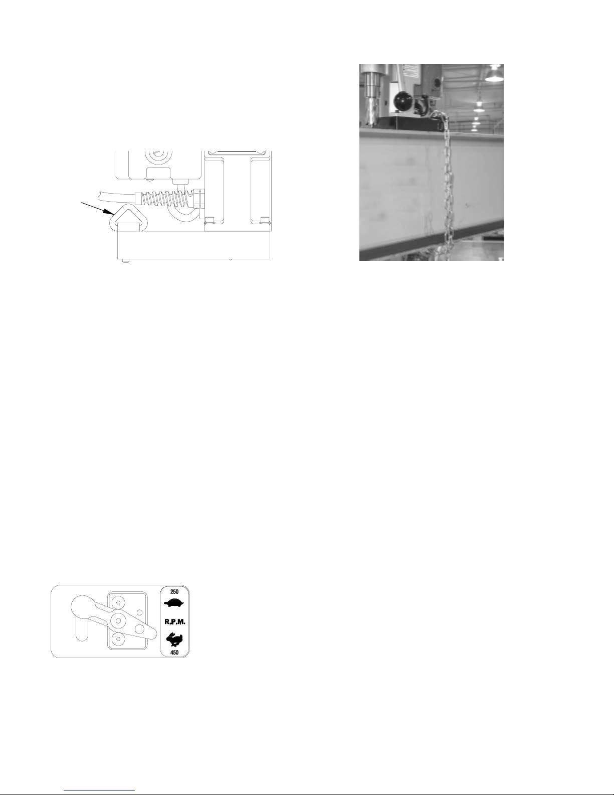
25. SafeElectricalConnection
Wet electrical connections are
shock hazards. To prevent the
cutting fluid from traveling along
the cord and contacting the plug
or power outlet, tie a drip loop as
shown at right. Also elevate
extension cords or gang box
connections.
26. Save These Instructions
IMPORTANTSAFETYINSTRUCTIONS

REVIEWOPERATIONOFCONTROLS
BEFOREINSTALLINGAROTABROACHCUTTER
IMPORTANT: Before turning on the machine, it is impera-
tive that the operator understands the interrelated func-
tionsoftheSAFETYSWITCH,GLIDEPOSTS,
MAGNET SWITCHES, AND MOTOR SWITCHES.
1. Place Magnetic Drill on clean, flat steel plate that is at
least 3/8" thick.
2. Plug unit into proper AC power source. DO NOT use with
DC power.
3. Locate the Magnet ON and OFF switches and the MOTOR
ON and OFF switches as shown below.
MOTOR ON SWITCH —Starts the motor (will not function
unless the magnetic base is energized and the safety switch
is activated).
MOTOR OFF SWITCH —Deactivates motor. Magnetic base
remains energized and safety switch activated.
FEED RATE L.E.D. —Indicates status of power source to the
unit and cutting performance:
Unit plugged in, no load Green Solid
Magnet On, no load Green Solid
Motor On, no load Amber
Ideal Operating Range Flashing Green
Excessive load Solid Red
Low Voltage (when plugged in) Flashing Red
MAGNET ON SWITCH —Energizes the magnetic base and
activates the safety switch. Motor can now be started by
pushing the MOTOR ON switch.
MAGNET OFF SWITCH —De-energizes the magnetic base
and deactivates MOTOR ON switch. (Note: MAGNET OFF
switch will not function while motor is on.)
SAFETY SWITCH —Located in base of drill. Enables motor
operation only when magnet is properly seated on a clean
and flat work surface. Turns motor off if drill unit
should lift or shift while cutting (Fig. 6).
GLIDE POSTS —Lifts magnet and breaks residual magnetic
energy after magnet is turned off. It also acts as a glide point
when drill is being moved from one position to another on the
work surface, thus minimizing wear on magnet. It also
permits easier repositioning and protects the safety switch.
SAFETYSWITCHADJUSTMENT
1. Unplug unit from power source and place it on a flat
sheet of steel that is at least 3/8" thick. Only magnet
portion should be on steel plate. Rear of magnet
(containing Glide Post) should hang over the edge of the
steel plate.
2. Remove Access Hole Screw (04156) from front of
housing.
3. Insert 5/32" Allen Wrench into access hole and back off
(counterclockwise) Microswitch Adjusting Screw (10969)
about three full turns.
4. Turn adjusting screw in (clockwise) about 1/8 turn at a
time (removing wrench, plugging motor to power source,
and turning magnet and motor ON each time) until you
find exactly where motor starts.
CAUTION —Turn switches OFF and unplug motor from
power source prior to each adjustment.
5. After determining point where motor starts, turn adjust-
ment screw clockwise one and a half turns.
6. Plug unit to power source. Turn Magnet and Motor
switches ON. Strike side of magnet at rear with rubber
hammer. Motor should shut off before the magnet
moves 3/4" in any direction.
7. Replace Access Hole Screw.
NOTE: Safety Switch adjustment should be checked
regularly following the procedure outlined in Step 6
above.
Access screw
(P/N 04156)
Safety Switch
Pivot Point

MAINTENANCE
In order to minimize wear on moving parts and to insure
smoother operation and longer life for your magnetic drill, the
following maintenance should be done periodically, based on
use.
1. Regularly tighten all fasteners and replace any worn
components.
2. Check motor brushes and replace if worn.
3. Check power cord and motor cord. If cracked or frayed,
return to authorize repair center for replacement.
REVERSINGTHEFEEDHANDLEASSEMBLY
1. Remove hub by turning mounting screw counter clock
wise.
2. Remount hub by aligning locator pins with matching holes
in feed gear and tightening screw.
INSTALLATIONOF CUTTING FLUIDBOTTLE
1. With Magnetic Drill in operating position, turn feed handle
so that cutter and pilot are above the work surface.
2. Set coolant bottle in carrying handle yoke with valve
facing toward the spindle of the drill. Press down to seat
nipple into port.
3. Tighten mounting screw on back of coolant bottle.
4. To test cutting fluid flow (with the magnet ON and motor
OFF), feed the arbor gently toward the work surface until
the pilot is pushed up into the cutter. Open valve on
coolant bottle cap. Fluid should filter down onto the work
surface through the groove in the pilot.
“ON”
“OFF”
Mounting
Screw
5. To insure proper cutter lubrication, always make sure
that the slot in the pilot is kept clean.
ROTABROACHCUTTERINSTALLATION
1. Disconnect from power source.
2. Lay drill on its side with feed handles up or be sure Arbor
clears table if unit is in normal operating position.
3. Remove set screws from spindle.
4. Insert proper pilot in shank end of Rotabroach Cutter. Pilot
#24131 is recommended for use with spring loaded
ejection on cutters 3/4”diameter and larger.
5. Insert Rotabroach Cutter until flats on cutter shank are
aligned with set screw holes and are exactly perpendicular
to axis of set screw holes. If 1/2" diameter shank cutter
is used, slip (10851) Arbor Adapter over the cutter shank
with adapter hole positioned exactly over flat on cutter
shank prior to inserting into Arbor bore.
6. Insert set screws and tighten. Check to be certain that
cutter is secure.
1. With Magnetic Drill in operating position, turn feed
handle so that cutter and pilot are above the work
surface.
2. Turn cutting fluid bottle valve to “OFF”position.
3. Remove bottle cap, fill with cutting fluid and replace cap.
4. Open cap vent by turning knurled screw 2 turns.
5. Test metering capabilities (MAGNET ON - MOTOR OFF)
by feeding the Arbor gently toward work surface until pilot
is pushed up into Cutter, thus allowing fluid to filter down
onto work surface through groove in pilot.
OPERATIONOFCUTTINGFLUIDBOTTLE
Note: As quill is fed toward material, fluid is drawn from
the bottle. As quill is returned to it’s starting position, fluid
will return to the bottle.
Note: Valve intended for “ON-OFF”operation only. Trying
to regulate coolant-flow with valve may cause valve to
leak. Coolant flow has been pre-determined.
See Page 10 for optional Pressurized Coolant Bottle
Assembly.

Always remember that the magnet's holding power is directly
related to the workpiece thickness and surface condition.
Since magnetic attraction diminishes with thinner material or
rough surfaces, mechanical clamping of drill unit to the
workpiece should be used when cutting thin material (3/8" or
less) or material with uneven surfaces.
Note: Always form a loose knot in the power cord close to
the molded plug. This prevents cutting fluid from running
down the cord and into power receptacle.
1. Make sure workpiece and bottom of magnet are free of
chips, oil, etc.
2. Secure unit to workpiece with safety chain.
3. Position drill by sliding it and gently feeding Arbor so that
pilot point is touching center of hole to be drilled.
4. Turn magnet ON by pressing the MAGNET ON button.
5. Select the proper RPM for the cutter diameter you are
using. Use the 450 setting for 7/16”thru 1-1/16”diameter
and use the 250 setting for 1-1/8”thru 2-3/8”diameters.
Note: The RPM settings for the diameter ranges are to be
used as starting points only. Setting may vary per application.
6. Turn Feed Handle, raising the cutter until the pilot is
above the work surface.
7. Open the cutting fluid bottle valve.
USEOFSAFETYCHAIN
The safety chain should be used to prevent the drill unit from
falling in the event of a power failure or if the magnet breaks
loose from the work surface. The safety chain should be
attached to the drill by running it through the “D”ring located
at the rear of the magnet, and tightly secured.
OPERATINGINSTRUCTIONS
8. Make certain that cutter is clear of workpiece and turn
motor ON by pressing the MOTOR ON button.
9. Feed Rotabroach Cutter slowly into workpiece. Only
after cutting path is established to a depth of about 1/16"
can full force be applied to feed handles.
10.Ease up on feed pressure as cutter starts breaking
through.
11. At conclusion of cut, turn motor OFF by pressing motor
STOP button. Turn Feed Handles to raise Arbor thereby
ejecting the slug if it hasn't already fallen free.
12.Close the cutting fluid bottle valve.
13.Turn magnet OFF by pressing the magnet OFF button.
As the magnet de-energizes, the rear of the magnet
should lift up off the work surface.
14.Disconnect from power source.
15.If necessary, remove chips from cutter and magnet,
preferably wearing leather work gloves and/or with pliers.
16.Disconnect safety chain and you are ready to move unit
to new drilling position.
Special Instructions for Horizontal or Overhead Operation
1. Always Use Safety Chain.
2. Use grease or animal-fat base solid lubricant applied
liberally to cutter.
3. For horizontal use, apply cutting fluid to external parts of
cutter with plastic bottle or oiling can, or use the optional
pressurized coolant bottle assembly (P/N 24140).
“D”Ring
For 1-1/8”thru 2-3/8”
For 7/16”thru 1-1/16”

HINTSFORSMOOTHEROPERATION
1. Keep insides of Rotabroach Cutter clear of chips. Chips
will interfere with cutting to maximum depth as well as
impede free oil flow from arbor to work and can
cause cutter breakage.
2. Keep workpiece, machine, arbor and Rotabroach Cutter
free of chips and dirt.
3. Tighten all bolts regularly.
4. We highly recommend using a light viscosity cutting fluid
(preferably Hougen Cutting Fluid).
5. Occasionally check metering of cutting fluid flow.
Lack of coolant may cause Rotabroach Cutter to freeze
in cut, slug to stick, and may result in poor cutter life.
6. Always start cut with light feed pressure and then
increase sufficiently to achieve maximum cutting rate.
7. Ease off on pressure as cutter begins to break through
at end of cut.
8. Keep magnet and cutter free of chips and dirt.
9. When slug hangs up in cutter, bring cutter down on a flat
surface. This will normally straighten a cocked slug,
allowing it to be ejected.
10.Cut overlapping holes as illustrated, using minimum
steady pressure. When cutter is removing material
whose cross-section is half or less than the cutter
diameter, pilot should be removed and tool should be
fed with care. External lubrication should be used.
Note: When cutting in this manner, cutting fluid may
escape from the cutting area. Tool should be fed with
care, using external lubrication.
11.When cutting large diameter or deep holes, it may be
necessary to stop in the middle of the cut to add cutting
fluid to the reservoir and also remove chips from around
the Arbor. When doing this, do not raise the cutter out of
the hole. Doing so can allow chips to get under the
teethof the cutter and make it difficult to restart the cut.
24072 ARBOR ASSEMBLY
Item
No. Description Qty Part
No.
1 Retaining Ring 1 24164
2 Washer 1 24165
3 Quill ssy 1 24016
4 Thrust washer 1 24091
5 Thrust Bearing 1 24094
6 Seat Thrust washer 1 24013
7 rbor 1 24163
8 Set Screws 2 40222

* Complete drill includes Arbor, but does not include Cutters or Pilots.
**Complete drill includes Arbor, Pilot, and No.# 40040 Arbor Adapter, but does
not include Cutters. Prices for additional gear sets available on request.
OPTIONAL PRESSURIZED COOLANT BOTTLE ASSEMBLY
Part Number 24140
HOUGEN PORTABLE MAGNETIC DRILLS
Item
No. Description
Q
ty
Req'd.
Part
No.
1 Bracket 1 24133
2 Barbed Insert 1 24148
3 Valve 1 24128
4 Adaptor 1 24132
5"O" Rin
g
1 24123
6 lamp 1 24149
7 aptive Screw 1 24110
8 Nylon Washer 1 24168
9Bottle, 1
g
allon 1 24127
Model
No. Description Max. Hole Capacity,
Inches Cutters
Dia. Depth
HMD100 Complete Drill* with carrying case, 450 rpm motor - 115V 1-1/16 3/4 Use "17,000-Series"
Cutters
HMD500 Complete Drill* withcarrying case, 250/450 rpm motor - 115V 2-3/8 3
Use "12,000-Series"
Cutters
10904 Complete Drill* with450 rpm motor - 115V 1-3/8 2
10909 Complete Drill* with 350 rpm motor - 230V 2-1/16 3
10909S Complete Drill* with 350 rpm motor - 230V 2-1/16 3
10914 Complete Drill* with350 rpm motor - 115V 2-1/16 3
10914S Complete Drill* with 350 rpm motor - 115V 2-1/16 3
10925 Power Feed Drill* with350 rpm motor - 115V 2-1/16 3
10926 Power Feed Drill* with 350 rpm motor - 230V 2-1/16 3
10915 Complete Drill** withdual speeds, 115V motor 3-1/16 3 Use "42/43,000-
Series" Cutters
10916 Complete Drill** withdual speeds, 230V motor 3-1/16 3

HMD500MOTORASSEMBLY
Det. PartNo. Description Req'd.
1 24156 HOUSING-MOTOR w/BRUSH HOLDER 1
2 24066 DOOR-ACCESS (MOTOR HOUSING 1
3 24041 ARMATURE-PQ FRAME ASSY 1
4 24042 FIELD- PQ FRAME w/MOTOR CORD 1
5 40373 STRAIN-RELIEF FOR .340 OD CORD 1
6 24080 SCR-SELF TAP #10 X 3-1/4 TYPAB 2
7 24153 SCR-SELF TAPPING #10X1/2"PN HD 2
8 24093 WASHER-SPRING 26MM OD.41MM THK 1
9 24045 BRUSH-CARBON 2
10 24044 CAP-BRUSH 2
11 24108 CONNECTOR-RECEPTACLE HSG
2CRKT 1
12 24114 BAFFLE-MOTOR (NYLON 6/6) 1
13 24059 LABEL-MOTOR ROTABROACH
(Not Shown) 1
14 24058 LABEL-MOTOR SPECIFICATIONS
(Not Shown) 1
15 04171 MOTOR CORD ASSEMBLY 1
16 24098 BEARING-ARMATURE-GEARBOX 1
17 24097 BEARING-ARMATURE-MOTOR HOUSING 1

HMD500HOOK- UP DIAGRAM
Feed Rate L.E.D. Indicates status of power
source to the unit and cutting performance
Unit plugged in, no load Green Solid
Magnet On, no load Green Solid
Motor On, no load Amber
Ideal Operating Range Flashing Green
Excessive Load Solid Red
Low voltage (when plugged in) Flashing Red
Det. Part No. Description Req'd.
Control Panel Assembly (P/N 24130)
1 24117 CIRCUIT BOARD - PUSH BUTTON 1
2 01226 GUARD-PUSHBUTTON SWITCH 1
3 02409 SEAL-SWITCH 15/32-32 GREEN 2
4 24135 L.E.D.-CLEAR LENS COVER 1
5 01228 SEAL-SWITCH 15/32-32 RED 2
Circuit Board Assembly (P/N 24191)
6 03868 SCR-PANHD #6-32 X 3/16 ZINC 5
7 24190 CIRCUIT BOARD - POWER 1
8 24142 COVER-WATER SPLASH-CIRC. BRKR. 1
9 03995 VIBRATION MOUNT 5
10 24141 CIRCUIT BREAKER - 14 AMP 1
Wire Harness Assembly
11 24008 WIRE HARNESS ASSEMBLY 1

HOUGENHMD500

HMD500 PARTS LIST
Part
No. Description Req'd.
01116 SCR-SHC #10-32 X 1 4
01447 HANDLE-FEED; .50 DIA. X 4.94 OAL 3
04156 SCR-BHSCS 5/16-18 X 1/4" LON 1
04158 SCR-SELF-THD #10-24 X 3/8 TYPE F 1
04159 SC R-LHSCS #10- 32 X 5/8" 2
0 4 20 7 S CR S O C SET 3 /8 -16 1
04307 WA SHER FLAT #10 4
10560 WA SHER-#10 EXT. TOOTH LOCK 1
10570 KNOB-FEED 1-23/32 DIA. 1/2-20 THD. 3
10632 RIN -RETA ININ .656 NOM. I.D. 1
10638 BEA RIN -ASSY SAFETY SWITC H 1
10967 CLIP-MICROSWITC H MOUNT IN 1
10968 SP . .045 X .30 O.D. 1
10969 SC R -SHC #10 -32 2
10970 BRACKET 1
10971 SCR-SHC 1/4-20 2
10972 SCR-BHC #6-32 2
10973 NUT-HEX #6-32 2
10974 RIN -RETA ININ 1.00 NOM I.D. 1
10975 SEAL-ASSY SAFETY SWITCH 1
10983 SHIELD MICROSWITCH 1
24011 HUB A SS'Y- FEED 1
24017 EAR SHIFT HA NDLE 1
24026 EAR- 32 & 39 TOOTH 1
24027 EAR & SHA FT ASS'Y #2 1
24032 SPLINE SHAFT EXTENSION 1
24033 HANDLE, CARRYIN -MACHINED 1
24036 WASHER EAR SHIFT SPACER 2
24037 PI N- DOWEL 3/16 X 1- 1/4 1
24038 EAR SHIFT PIN 1
24039 EA R SHIFT YOLK 1
24040 FEED EAR 1
24046 EAR SWITCH PLATE 1
24049 PLUN ER BODY-SAFETY SWITCH 1
24051 STOP-QUILL TRA VEL 1
24053 SPRIN PLUN ER NOSE 2
24063 MA NET ASSEMBLY 1
24064 MOTOR ASSEMBLY 1
24067 HOUSIN ASSEMBLY 1
24070 COOLANT BOTTLE ASSEMBLY 1
24072 QUILL & ARBOR ASSY 1
Part
No. Descr iption Req'd.
24073 POWER CORD ASSY 1
24077 SCR-SHCS #10-32 X 7/8" LON 4
24087 BEARIN BUSHIN 2
24082 SC R -SHC S #6-3 2 3
24083 SPRIN -COMPRESSION .845 OD 1
24092 SPRIN WA SHER 1
24095 LIP SEAL 1
24100 BALL BEARIN 9
24101 SCR-SHSLD 1/4-3/8 1
24102 SPLINE SHAFT A SSY. 1
24103 SPUR EAR & SHAFT A SSY 15 TOOTH 1
24104 SPUR EAR & SHAFT A SSY 14 TOOTH 1
24105 SPUR EA R & SHAFT A SSY 15-20
TOOTH 1
24109 SCR-CA PT. T HUMB 1/4-20 1
24111 MICRO-SWITCH ASSEMBLY 1
24115 CA SE-CA RRYIN HMD500 DRILL 1
24124 CA P-COOLANT BOTTLE W/VENT 1
24125 SPRIN -COMP .30 OD .38L .047 WD 1
24126 O-RIN -7/16 ID 5/8 OD 3/32 W 1
24130 PUSH BUTTON ASSEMBLY 1
24143 PLATE-SPRIN & CHA IN HOLDDOWN 1
24144 RIN -"D" X 1" WIDE 1
24146 EXTENSION PLUN ER 1
24147 SPRIN -COMP .30 OD X 1.13 L X .03 1
24157 COVER AND BEARIN A SSY. 1
24158 EAR BOX AND BEARIN ASSY. 1
2 4 15 9 E A R SWIT C H A ND P LUN ER A SSY. 1
24167 SPRIN 1.25 X .051 2
24168 WAHER FLAT NY LON 1
24191 CIRCUIT ASSEMBLY 1
40038 SCR-SHC #10-32 X 5/8 6
40077 SCR-SHC 1/4-20 X 1 7
40108 SCR-SHC 1/4-20 X 1-1/4 1
40222 SCR- SOC SET 7/16-14 2
40402 WASHER FLAT 1
40449 SPACER 2
41044 SCR-BHC #10-32 X 3/8 9
41046 SCR-SHC #10-32 X 1/2 4
50038 WASHER HELICAL #10 4
51042 SCR-SHC 1/4-20 X 3/8 2
90028 WASHER HELICA L 1/4" 4

NEW
“12,000-Series”Cutter Pilots
Pilots for
Cutter Dia. Part No.
1" D.O.C. Part No.
2" D.O.C. Part No.
3" D.O.C.
7/16" & 12mm 10531 10532 --
1/2 -11/16" &
13 - 18mm 10533 10534 --
3/4 - 2-3/8" &
19 - 51mm 10527 10528 24131
3/4 - 2-3/8" &
19 - 51mm 24131
NNEW
Note: Part No. 24131 for use with spring-
loaded ejection on Model HMD500
“12,000-Series”Tap Drills
Dia.
(in ./mm ) Dec.
Equiv. Part No.
1" D.O.C. Part No.
2" D.O.C. Part No.
3" D.O.C.
3/4" Diameter Shank Cutters
Use with Pilot 10531 or 10532
7/16 .4375 12114 12214 --
12mm .4724 12312 12412 --
3/4" Diameter Shank Cutters
Use with Pilot 10533 or 10534
1/2 .5000 12116 12216 --
9/16 .5625 12118 12218 --
5/8 .6250 12120 12220 --
11/16 .6875 12122 12222 --
13mm .5118 12313 12413 --
14mm .5512 12314 12414 --
15mm .5906 12315 12415 --
16mm .6299 12316 12416 --
17mm .6693 12317 12417 --
18mm .7087 12318 12418 --
3/4" Diameter Shank Cutters
Use with Pilot 10527, 10528 or 24131
3/4 .7500 12124 12224 3-12224
13/16 .8125 12126 12226 3-12226
7/8 .8750 12128 12228 3-12228
15/16 .9375 12130 12230 3-12230
1 1.0000 12132 12232 3-12232
1-1/16 1.0625 12134 12234 3-12234
1-1/8 1.1250 12136 12236 3-12236
1-3/16 1.1875 12138 12238 3-12238
1-1/4 1.2500 12140 12240 3-12240
1-5/16 1.3125 12142 12242 3-12242
1-3/8 1.3750 12144 12244 3-12244
1-7/16 1.4375 12146 12246 3-12246
1-1/2 1.5000 12148 12248 3-12248
1-9/16 1.5625 12150 12250 3-12250
1-5/8 1.6250 12152 12252 3-12252
1-11/16 1.6875 12154 12254 3-12254
1-3/4 1.7500 12156 12256 3-12256
1-13/16 1.8125 12158 12258 3-12258
1-7/8 1.8750 12160 12260 3-12260
1-15/16 1.9375 12162 12262 3-12262
2 2.0000 12164 12264 3-12264
2-1/16 2.0625 -- 12266 --
2-1/8 2.1250 -- 12268 --
2-3/16 2.1875 -- 12270 --
2-1/4 2.2500 -- 12272 --
2-5/16 2.3125 -- 12274 --
2-3/8 2.3750 -- 12276 --
Dia.
(in ./mm ) Dec.
Equiv. Part No.
1" D.O.C. Part No.
2" D.O.C. Part No.
3" D.O.C.
3/4" Diameter Shank Cutters
Use with Pilot 10527, 10528 OR 24131
19mm .7480 12319 12419 12519*
20mm .7874 12320 12420 12520*
21mm .8268 12321 12421 12521*
22mm .8661 12322 12422 12522*
23mm .9055 12323 12423 12523*
24mm .9449 12324 12424 12524*
25mm .9843 12325 12425 12525*
26mm 1.0237 12326 12426 12526*
27mm 1.0630 12327 12427 12527*
28mm 1.1020 12328 12428 12528*
29mm 1.1417 12329 12429 12529*
30mm 1.1812 12330 12430 12530*
31mm 1.2205 12331 12431 12531*
32mm 1.2598 12332 12432 12532*
33mm 1.2993 12333 12433 12533*
34mm 1.3386 12334 12434 12534*
35mm 1.3779 12335 12435 12535*
36mm 1.4174 12336 12436 12536*
37mm 1.4567 12337 12437 12537*
38mm 1.4961 -- 12438 12538*
39mm 1.5354 -- 12439 12539*
40mm 1.5748 -- 12440 12540*
41mm 1.6142 -- 12441 12541*
42mm 1.6535 -- 12442 12542*
43mm 1.6929 -- 12443 12543*
44mm 1.7323 -- 12444 12544*
45mm 1.7717 -- 12445 12545*
46mm 1.8110 -- 12446 12546*
47mm 1.8504 -- 12447 12547*
48mm 1.8898 -- 12448 12548*
49mm 1.9291 -- 12449 12549*
50mm 1.9685 -- 12450 12550*
51mm 2.0079 -- 12451 12551*
“12,000-Series”Rotabroach Cutters
NEW
Cutter
Diameter
(inches) Thread Dec.
Equiv. Part No.
1" D.O.C. Part No.
2" D.O.C.
7/16 1/2-13 .4375 12114 12214
35/64 5/8-11 .5469 12117 12217
21/32 3/4-10 .6563 12121 12221
25/32 7/8-9 .7812 12125 12225

Hougen Manufacturing, Inc.
P.O. Box 2005 •Flint, MI 48501-2005
3001 Hougen Drive •Swartz Creek, MI 48473
Phone (810) 635-7111 •FAX (810) 635-8277
Email: [email protected]
Online: www.hougen.com
Form #04174 7/01 1.5M Printed in U.S.A.
Weld Tooling Corp.
3001 W. Carson Street
Pittsburgh, PA 15204
(412) 331-1776
Factory Authorized Warranty Repair Centers
West
A.C.C.Machinery Co.,Inc
747 Grand Avenue
Phoenix, AZ 85007
(602) 258-7330
ATS Repair Center
2400 West Directors Row
Salt Lake City, UT 84125
(801) 972-3182
Caltool Industrial Supply
470 Hester Street
San Leandro, CA 94577
(510) 729-0600
Kenbil Service Co.
2900 Adams St., B-15
Riverside, CA 92504
(909) 689-6633
Quimby Welding Repair
1603 Northwest 14th Ave.
Portland, OR 97209
(503) 221-1100
Canada
OK Power Tool
14740 115 Avenue
Edmonton, Alberta
Canada T5M 3B9
(403) 454-5111
Outiltech Orleans, Inc.
5695 Rue Rideau
Quebec, Quebec
Canada G2E 5V9
(418) 877-7776
Edward H. Pope, Ltd.
10 Imperial Court
Brampton, Ontario
Canada L6T 4X4
(905) 458-4800
Power Tool Clinic
19835-56 Ave
Langley, B.C.
Canada V3A 3V1
(604) 530-3550
O.T.I. Repair Center Inc
195 Rue Henry Bessemer
Bois Des Filion
Quebec Canada J6Z 4S9
(450) 965-2224
Pennsylvania Tool Sales
and Service, Inc.
625 Bev Road
Youngstown, OH 44512
(330) 758-0845
Southeast
Gardner Southeast Repair
807 Meroney Street
Chattanooga, TN 37405
(423) 756-4722
Mid-South Welding Supply
505 51st. Avenue
Meridian, MS 39307
(601) 483-9331
South
Allied Sales & Service Co.
1508 River Oaks Rd., West
Jefferson, LA 70123
(504) 734-9566
Wilbanks Repair Center
5532 S. 94th East Ave.
Tulsa, OK 74145
(918) 627-8445
Midwest
Ceekay Repair Center
5835 Manchester Ave.
St. Louis, MO 63110
(314) 644-3500
Miller Industrial Supply Co.
1695 N. 21st
Decatur, IL 62525
(217) 428-7787
Hougen Manufacturing, Inc.
3001 Hougen Drive
Swartz Creek, MI 48473
(810) 635-7111
Westbrook Engineering
23501 Mound Road
Warren, MI 48091
(810) 759-3100
Southwest
Arcmaster Repair Center
301 Woodrow Ave
Fort Worth, TX 76105
(817) 531-8101
Rex Supply Repair Center
3715 Harrisburg
Houston, TX 77003
(713) 222-2251
United States - East
A&A Industrial Supplies Inc.
251 Meacham Ave.
Elmont, NY 11003
(516) 437-0114
Awisco Repair Center
55-16 43rd Ave.
Maspeth, NY 11378
(718) 786-7788
Boyer Machinery Co.
2280 Wyandotte Road
Willow Grove, PA 19090
(215) 657-2242
Colony Hardware Supply Co.
15 Stiles Street
New Haven, CT 06512
(203) 466-5252
Hanes Supply Repair Center
10 Cairn Street
Rochester, NY 14609
(716) 826-2636
N.H. Bragg & Sons
90 Perry Road
Bangor, ME 04401
(207) 947-8611
Table of contents
Other Hougen Drill manuals

Hougen
Hougen HMD501 User manual

Hougen
Hougen HMD904 SERIES User manual

Hougen
Hougen Rotabroach HMD100 User manual

Hougen
Hougen 10925 User manual

Hougen
Hougen HMD130 User manual

Hougen
Hougen HMD151 User manual

Hougen
Hougen HMD904 User manual

Hougen
Hougen HMD915 Series User manual

Hougen
Hougen HMD115 Series User manual

Hougen
Hougen HMD505 SERIES User manual

Hougen
Hougen HMD904 User manual

Hougen
Hougen HMD904 User manual

Hougen
Hougen HMD150 SERIES User manual

Hougen
Hougen 925102 User manual

Hougen
Hougen 10914S User manual

Hougen
Hougen HMD917 Series User manual

Hougen
Hougen HMD904 SERIES User manual

Hougen
Hougen HMD151SGP User manual

Hougen
Hougen HMD904 SERIES User manual

Hougen
Hougen HMD904C User manual