Quick Start Guide
HD 360 Panoramic
Fisheye Network Camera
Features and Specifications
A. Overview
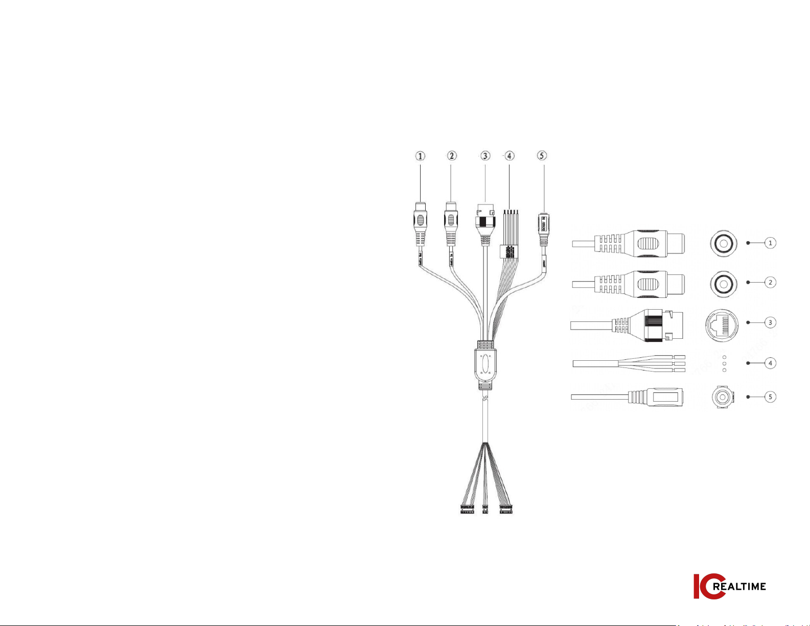
B. Cable Interface
Camera Installation
A. Installation Steps
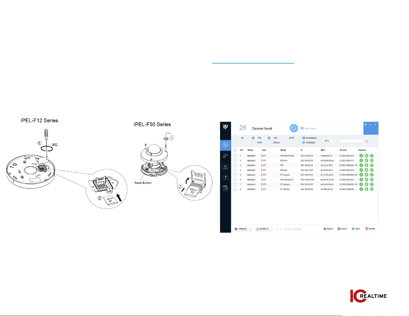
B. Restore Factory Defaults and
Installing SD card
Quick Configuration Tool
A. Overview
B. Operation
Web Operation
A. Network Connection
B. Login and Logout
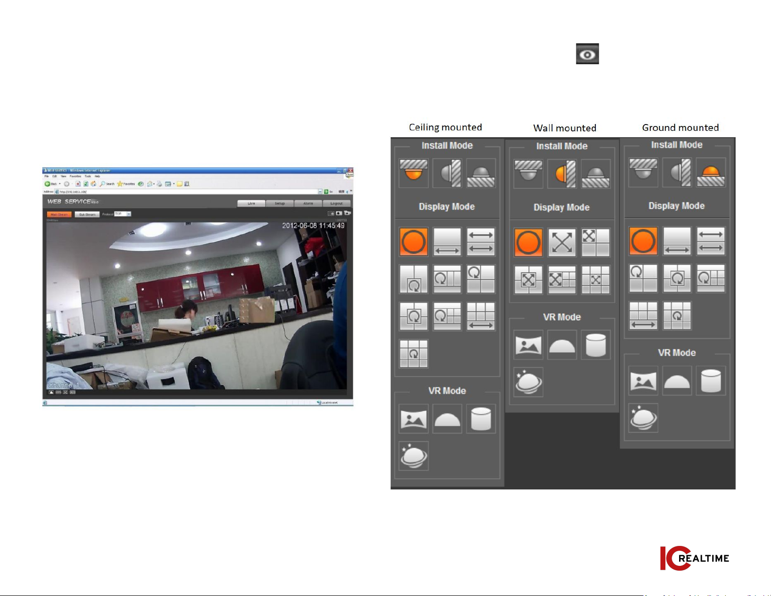
C. Fisheye Dewarping
Appendices
D. FAQ
E. Toxic or Hazardous Elements
2
2
3-4
5
5
5-6
7
7-8
8-9
10
11
Table Of Contents
MARGIN
GUIDES
To see the guides to go:
View / Guides / Show
Guides
www.icrealtime.com
IMPORTANT SAFEGUARDS AND WARNINGS
Electrical Safety
All installation and operation here should conform to your local electrical safety codes. The
power shall conform to the requirement in the SELV (Safety Extra Low Voltage) and the
Limited power source is rated 12V DC in the IEC60950-1. This series product supports PoE
too. Please note: Do not connect these two power supplying sources to the device at the same
time; it may result in device damage! We assume no liability or responsibility for all the fires or
electrical shock caused by improper handling or installation. We are not liable for any problems
caused by unauthorized modification or attempted repair.
Transportation Security
Care must be given to avoid heavy stress, violent vibration or water damage during
transportation, storage and installation.
Installation
Do not apply power to the camera before completing installation. Please install the proper
power cut-off device during the installation connection. Always follow the instruction guide the
manufacturer recommended.
Qualified engineers needed
All the examination and repair work should be done by the qualified service engineers. We are
not liable for any problems caused by unauthorized modifications or attempted repair.
Environment
This series network camera should be installed in a cool, dry place away from direct sunlight,
inflammable, explosive substances and etc. Please keep it away from the electromagnetic
radiation object and environment. Please make sure the CCD (CMOS) component is out of the
radiation of the laser beam device. Otherwise it may result in CCD (CMOS) optical component
damage. Please keep the sound ventilation. Do not allow the water and other liquid falling into
the camera. Lightning-proof device is recommended to be adopted to better prevent lightning
damage. The grounding studs of the product are recommended to be grounded to further
enhance the reliability of the camera.
Daily Maintenance
Please shut down the device and then unplug the power cable before you begin daily
maintenance work. Do not touch the CCD (CMOS) optic component. You can use the blower to
clean the dust on the lens surface. Always use the dry soft cloth to clean the device. If there is
too much dust, please use the water to dilute the mild detergent first and then use it to clean
the device. Finally use the dry cloth to clean the device. Please put the dustproof cap to protect
the CCD (CMOS) component when you do not use the camera.
Accessories
Be sure to use all the accessories recommended by manufacturer. Before installation, please
open the package and check all the components are included. Contact your local retailer ASAP
if something is broken in your package.