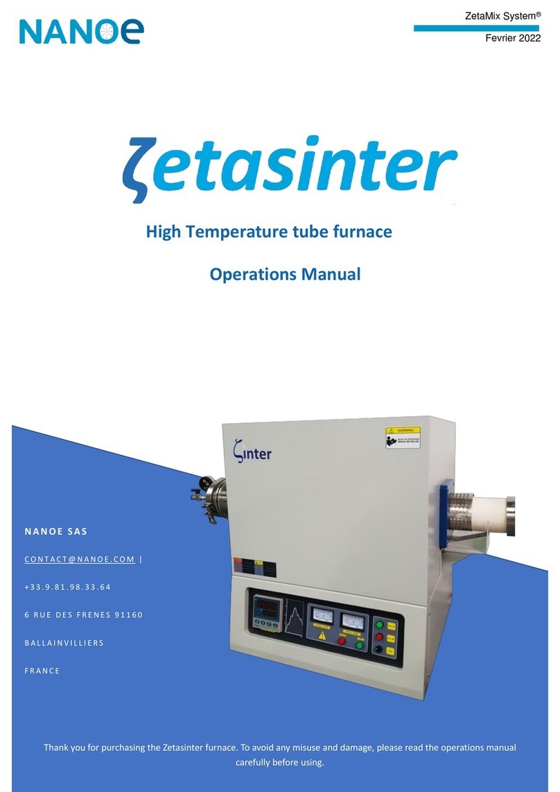
Ideal Vacuum Habanero P1012726 User manual

HRCF-08122022- V 1.1
USER MANUAL
Habanero™Spectroscopy
Reference Cell Furnace
(P1012726)

Copyright © 2022, Ideal Vacuum Products, LLC | (505) 872-0037 | [email protected] | www.idealvac.com
HRCF-08122022 - V 1.12
Ideal Vacuum warrants to the original purchaser, this product to be free from defects in workmanship
and materials for a period of 90 days from the original delivery date. The liability of Ideal Vacuum,
under this warranty, is limited to servicing, adjusting, repairing or replacing any unit or component
part which, at Ideal Vacuum’s sole discretion, is determined to have failed during normal, intended
use. This warranty does not cover improper installation, process related damage, product use
in any way other than dened in this manual, or any misuse, abuse, negligence, accident, or
customer modication to the product.
Prior to returning any product, we require that you contact us by phone or email to determine if
the issue can be resolved quickly. A technical support representative will work with you to resolve
the problem. If the issue cannot be resolved in that manner, we will issue an RMA number and
provide product return instructions.
THIS WARRANTY IS IN LIEU OF ALL OTHER WARRANTIES, EXPRESSED OR IMPLIED,
INCLUDING THE IMPLIED WARRANTY OF MERCHANTABILITY AND THE IMPLIED
WARRANTY OF FITNESS FOR USE OR FITNESS FOR A PARTICULAR PURPOSE. IDEAL
VACUUM SHALL NOT BE LIABLE UNDER ANY CIRCUMSTANCES FOR INDIRECT,
SPECIAL, CONSEQUENTIAL OR INCIDENTAL DAMAGES ARISING OUT OF THE USE OF
THE PRODUCT. THE TOTAL LIABILITY OF IDEAL VACUUM SHALL NOT EXCEED THE
PURCHASE PRICE OF THE PRODUCT UNDER ANY CIRCUMSTANCES.
CUSTOMER SERVICE AND SUPPORT
If you have any questions concerning the installation or operation of this equipment, or if you
need warranty or repair service, please contact us. Customer Service and Technical Support is
available weekdays, from 8am-5pm, Mountain Time.
Phone: (505) 872-0037
Fax: (505) 872-9001
Web: idealvac.com
INTELLECTUAL PROPERTY
At Ideal Vacuum we constantly strive to innovate and improve on existing products. Therefore,
specications and information are subject to change without notice. The Ideal Vacuum Logo
is a registered trademark, Habanero, AutoExplor, and the slogan “Our Products Develop
Tomorrow’s Technologies” are trademarks of Ideal Vacuum Products, LLC. Macor is a
registered trademark of Corning SAS. Windows is a registered trademark of Microsoft
Corporation. Variac is a registered trademark of Instrument Service Equipment, Inc. Reference
to products, trademarks, and registered trademarks owned by other manufacturers is made strictly
for informative purposes and are the sole properties of their respective owners.
Copyright © 2022, Ideal Vacuum Products, LLC. All rights reserved.
WARRANTY

Copyright © 2022, Ideal Vacuum Products, LLC | (505) 872-0037 | [email protected] | www.idealvac.com
HRCF-08122022 - V 1.1 3
TABLE OF CONTENTS
Warranty .......................................................................................................................................2
Customer Service and Support..................................................................................................2
Intellectual Property....................................................................................................................2
Safety............................................................................................................................................5
Important Safety Information.....................................................................................................5
Warning Symbols and Denitions .............................................................................................5
1. Overview ..................................................................................................................................6
1.1 Introduction ......................................................................................................................6
1.2 Physical Specications ....................................................................................................7
1.3 Available Wavelength Reference Cells............................................................................8
2. Basic Installation.....................................................................................................................9
2.1 Power and Control ...........................................................................................................9
2.2 Mounting ..........................................................................................................................9
3. Reference Cell Installation ...................................................................................................11
4. Window Replacement ...........................................................................................................14
4.1 Available Replacement Windows...................................................................................14
4.2 Window Replacement Procedure ..................................................................................15
5. Furnace Control ....................................................................................................................16
5.1 With IVP PID Heater Control..........................................................................................16
5.2 With Variable Transformer .............................................................................................17

Copyright © 2022, Ideal Vacuum Products, LLC | (505) 872-0037 | [email protected] | www.idealvac.com
HRCF-08122022 - V 1.14
LIST OF TABLES
Table 1 - Furnace specications................................................................................................7
Table 2 - Specications of available reference cells..................................................................8
Table 3 - Available replacement windows ...............................................................................14
LIST OF FIGURES
Figure 1 - Tapped mounting holes in base ................................................................................9
Figure 2 - Optical post legs for benchtop placement...............................................................10
Figure 3 - Optical table furnace mounting kit (P1012730).......................................................10
Figure 4 - Remove four end cap screws (LA-11-405) ............................................................. 11
Figure 5 - Grasp and pull on window retaining ring................................................................. 11
Figure 6 - Pull out from end cap..............................................................................................12
Figure 7 - Slide off ceramic holder ..........................................................................................12
Figure 8 - Seat the reference cell into the ceramic holder ......................................................12
Figure 9 - Slide the ceramic holder back onto the mounting rods...........................................13
Figure 10 - Seat the ceramic holder onto the reference cell ...................................................13
Figure 11- Insert the cell holder assembly into the furnace.....................................................13
Figure 12 - Remove screws in window retaining ring.............................................................15
Figure 13 - Carefully remove and replace window.................................................................15
Figure 14 - Plug furnace power and thermocouple cables into controller ..............................16
Figure 15 - Controller navigation buttons ...............................................................................16
Figure 16 - Initial furnace current and target temperatures....................................................17
Figure 17 - Set the furnace target temperature......................................................................17

Copyright © 2022, Ideal Vacuum Products, LLC | (505) 872-0037 | [email protected] | www.idealvac.com
HRCF-08122022 - V 1.1 5
SAFETY
Indicates an imminently hazardous situation that, if not avoided,
will result in death or severe injury.
Indicates an imminently hazardous situation that, if not avoided,
could result in death or severe injury.
Indicates a potentially hazardous situation that, if not avoided,
could result in moderate or minor injury. It may also be used to
alert against unsafe practices.
Indicates a potentially hazardous situation that, if not avoided,
could result in equipment or property damage.
Indicates helpful tips and recommendations, as well as information
for efcient, trouble-free operation.
WARNING SYMBOLS AND DEFINITIONS
This is the universal safety alert symbol. It is used to alert you to potential
personal injury hazards. Obey all safety messages that follow this symbol
to avoid possible injury or death.
Internationally recognized safety symbols may be used with safety warnings to specify the type of
hazard or a safety protocol to follow. For example:
Indicates safety glasses
are required
Indicates an electric
shock hazard
IMPORTANT SAFETY INFORMATION
Thank you for purchasing this equipment from Ideal Vacuum Products. We want you to operate
it safely.
hRead this manual and all associated equipment manuals before
installing or operating this equipment. Failure to follow the warnings
and instructions may result in serious injury or equipment damage.
hKeep this manual in a safe location for future reference.
hThis equipment should only be installed and operated by trained,
qualied personnel, wearing appropriate protective equipment.
hFollow all codes that regulate the installation and operation of this
equipment.

Copyright © 2022, Ideal Vacuum Products, LLC | (505) 872-0037 | [email protected] | www.idealvac.com
HRCF-08122022 - V 1.16
1. OVERVIEW
Ideal Vacuum’s Habanero™ is a benchtop sized reference absorbtion cell heating furnace for
spectroscopy, and can be used with all of our sealed wavelength reference cells. The Habanero
furnace provides a stable temperature and convenient package for many reference cell applications.
It provides an even, elevated temperature to maintain a constant absorption spectrum of tellurium
for laser locking and spectrum calibration. For applications where greater resolution is required,
it can be used in a saturated absorption system for doppler-free absorption spectroscopy. As
congured, the Habanero is ready for use in transmission spectroscopy.
With a maximum operating temperature of 900°C, the Habanero furnace is especially useful
for high temperature references such as tellurium and the excited states of iodine. With its wide
operating range from maximum to ambient, the Habanero can be used with all of Ideal Vacuum’s
sealed wavelength reference cells. Note that care must be taken not to exceed the damage
threshold temperature of alkali and organic reference cells.
Raising the temperature of a reference material that is solid under normal conditions increases the
number density of atoms or molecules in the gas phase. This increases the optical density of the
reference, increasing signal-to-noise ratios and the number of lines that can be condently used
to calibrate a spectrum. Raising the temperature also changes the distribution of populated states,
allowing access to calibration-quality absorption lines beginning from higher rotational, vibrational,
and even electronic states in wavelength ranges inaccessible at normal room temperature. Some
reference materials have absorption lines or peaks that move as a function of temperature. For
these materials, the Habanero furnace can provide the precise long-term temperature control
necessary to maintain laser calibration for the full duration of an experiment.
1.1 INTRODUCTION

Copyright © 2022, Ideal Vacuum Products, LLC | (505) 872-0037 | [email protected] | www.idealvac.com
HRCF-08122022 - V 1.1 7
1.2 PHYSICAL SPECIFICATIONS
Parameter Value
Maximum Heater Temperature 900°C (1652°F)
Minimum Heater Temperature Ambient
Window Diameter/Type Ø1” Uncoated UV Fused Silica, 5 mm Thick,
0.5°Wedge, Wavelength Range: 185-2100 nm
Maximum Window Thickness 8 mm (0.315 in.)
Heater Type Ceramic Fiber
Heater Bore Diameter 50.8 mm (2.0 in.)
Cell Holder Material Macor Ceramic
Maximum Cell Holder Sample Diameter 26 mm (1.024 in.)
Maximum Cell Length (in Holder) 139.7 mm (5.5 in.)
Maximum Mounting Rod Sample Diameter 41.3 mm (1.625 in.)
Maximum Cell Length (on Mounting Rods) 155 mm (6.1 in.)
Heater Sheath Material 304 Stainless Steel
Case Material 10 ga. 5052 H32 Aluminum
Maximum Case Temperature 130°C (266°F)
Cooling Passive Convection
Power Input 100-120 VAC, 50/60 Hz
Maximum Current 3.6 A
Heating Power 425 W
Power Cable 118 cm (3.9 ft.) long with NEMA 15-5 plug
Thermocouple Cable 118 cm (3.9 ft.), Type K Mini Male Connector
Recommended Controller IVP PID Heater Controller (P107361)
Physical Dimensions 212 x 129 x 142 mm (8.34 x 5.08 x 5.60 in.)
Minimum Top Clearance 305 mm (12 in.)
Minimum Side Clearance 76 mm (3 in.)
Recommended Underneath Clearance 76 mm (3 in.)
Weight 5.33 kg. (11.75 lb.)
Table 1 - Furnace specifications

Copyright © 2022, Ideal Vacuum Products, LLC | (505) 872-0037 | [email protected] | www.idealvac.com
HRCF-08122022 - V 1.18
1.3 AVAILABLE WAVELENGTH REFERENCE CELLS
Part # Material Chemical
Formula
Typical Temp.
Range
Wavelength
Range
Dimensions
(OD. x Length)
P1011696 Sodium Na 20-200°C 232-2338 nm 19 mm x 75 mm
P1011695 Potassium K 20-200°C219-4016 nm 19 mm x 75 mm
P1011689 Rubidium Rb 20-80°C 207-1529 nm 19 mm x 75 mm
P1011692 Isotopic
Rubidium
85Rb 20-80°C 207-1529 nm 19 mm x 75 mm
P1011693 Isotopic
Rubidium
87Rb 20-80°C 207-1529 nm 19 mm x 75 mm
P1011694 Cesium Cs 20-120°C 227-3613 nm 19 mm x 75 mm
P1012466 Methane Ch4Ambient
430-1050 nm
3050-3650 nm
7275-8300 nm
10 mm x 75 mm
P1012478 Ethane C2H6Ambient 3050-3650 nm 10 mm x 75 mm
P1012479 Propane C2H8Ambient 2950-4000 nm 10 mm x 75 mm
P1012480 Ethylene C2H4Ambient 3075-3650 nm 10 mm x 50 mm
P1012481 Isotopic
Acetylene
12C2H2Ambient 2985-3125 nm 10 mm x 50 mm
P1012482 Isotopic
Acetylene
13C2H2Ambient 2985-3125 nm 10 mm x 50 mm
P1012483
Isotopic
Carbon
Monoxide
12C16O Ambient
2300-2410 nm
(NIST Telecom
SRM 2515)
10 mm x 150 mm
P1012484
Isotopic
Carbon
Monoxide
13C16O Ambient
1595-1635 nm
2300-2410 nm
(NIST Telecom
SRM 2515)
10 mm x 150 mm
P1012485 Carbon
Dioxide CO2Ambient 2665-2855 nm 10 mm x 50 mm
P1011697 Water H2O -10-100°C 2500-2900 nm 19 mm x 75 mm
P1011698 Isotopic
Tellurium
130Te2550-800°C 420-540 nm 25 mm x 100 mm
P1010959 Iodine I220-70°C 500-910 nm 20 mm x 100 mm
Table 2 - Specifications of available reference cells

Copyright © 2022, Ideal Vacuum Products, LLC | (505) 872-0037 | [email protected] | www.idealvac.com
HRCF-08122022 - V 1.1 9
2.1 POWER AND CONTROL
The Habanero’s resistive heating elements are designed to be powered by 100-120 VAC, 50/60
Hz, 3.6 A and have a heating power of 425 W under these conditions. Reducing the voltage
results in a slower heating rate and reduced maximum temperature.
Power is supplied to the furnace via a permanently attached power cord with a standard NEMA
5-15 plug. The power plug must be connected to a power regulating device, such as our PID
heater controller (p. 16), a variable transformer (Variac), or another user supplied controller.
Direct connection to an unregulated power source (such as the wall or a power strip) will result in
overheating and permanent damage to the furnace.
For temperature monitoring, the Habanero is equipped with a type K thermocouple with a miniature
male straight blade connector.
2. BASIC INSTALLATION
2.2 MOUNTING
For adequate ventilation, at least 3” of clearance on each side and 12” above the furnace is
required. It must be placed on or mounted to a non-combustible working surface. We recommend
elevating it at least 3” above the surface to improve air ow.
The base of the Habanero has eight 8-32 tapped holes for mounting legs or posts.
When the furnace’s internal temperature is high, the furnace’s
exterior surface temperature can reach as much as 130°C (266°F).
Do not touch the furnace when it is heating. Do not put anything
on top of the furnace. Remove all combustibles from the furnace
vicinity (i.e., paper). Do not operate in a fully enclosed space.
Figure 1 - Tapped mounting holes in base

Copyright © 2022, Ideal Vacuum Products, LLC | (505) 872-0037 | [email protected] | www.idealvac.com
HRCF-08122022 - V 1.110
For benchtop use, we recommend using four 3 inch long optical posts for legs screwed in at each
corner of the furnace base (P1012739).
For easiest mounting to an optical table with standard 1” x 1” breadboard tapped holes, we
recommend our optical table furnace mounting kit (P1012736) (shown below), which includes
everything needed for a vibration-free, secure installation. Other optical table accessories are
available, including optical posts and holders in varied lengths, optic mounts, and breadboards.
Figure 2 - Optical post legs for benchtop placement (P1012739)
Figure 3 - Optical table furnace mounting kit (P1012736)

Copyright © 2022, Ideal Vacuum Products, LLC | (505) 872-0037 | [email protected] | www.idealvac.com
HRCF-08122022 - V 1.1 11
3. REFERENCE CELL INSTALLATION
It is not necessary to remove the furnace windows when installing
or replacing a reference cell.
Initial installation or replacement of the reference cell is done when the heater is cold (at ambient
temperature), and requires a 5/64” hex wrench. Wear gloves when performing this procedure.
1. On the side of the furnace opposite the power cable, unscrew the four 6-32 x 3/8” button
head screws on the end cap (LA-11-405) just inside the furnace case.
2. Grasp the window retaining ring and carefully pull the cell holder assembly out of the furnace.
Figure 4 - Remove four end cap screws (LA-11-405)
Figure 5 - Grasp and pull on window retaining ring

Copyright © 2022, Ideal Vacuum Products, LLC | (505) 872-0037 | [email protected] | www.idealvac.com
HRCF-08122022 - V 1.112
3. When the end cap is past the furnace case, grab the end cap and continue gently pulling
the cell holder assembly out.
4. Once the cell holder assembly is out of the furnace, slide off the rst ceramic holder.
5. Notice that the end cap optic hole is off-center. Slide the reference cell in between the rods,
cell stem pointing towards the larger side of the end cap. Seat the cell into the holder.
Figure 6 - Pull out from end cap
Figure 7 - Slide off ceramic holder
Figure 8 - Seat the reference cell into the ceramic holder

Copyright © 2022, Ideal Vacuum Products, LLC | (505) 872-0037 | [email protected] | www.idealvac.com
HRCF-08122022 - V 1.1 13
6. Take the previously removed ceramic cell holder and slide it, circular end rst, back onto
the mounting rods.
7. Carefully slide the ceramic holder over, and seat it on, the reference cell.
8. Carefully slide the cell holder assembly back into the furnace, cell stem up.
9. Secure the assembly to the furnace with the four 6-32 x 3/8” screws. Use a 5/64” hex wrench.
Figure 9 - Slide the ceramic holder back onto the mounting rods
Figure 10 - Seat the ceramic holder onto the reference cell
Figure 11- Insert the cell holder assembly into the furnace

Copyright © 2022, Ideal Vacuum Products, LLC | (505) 872-0037 | [email protected] | www.idealvac.com
HRCF-08122022 - V 1.114
4.1 AVAILABLE REPLACEMENT WINDOWS
4. WINDOW REPLACEMENT
Two 1” diameter, uncoated, wedged fused silica windows are included standard with the Habanero
furnace. Window replacements may be required if the optics become degraded over time due to
elevated temperatures. If focusing or other special considerations are required for an application,
the researcher can substitute windows with their own optics. The furnace uses 1 inch diameter
windows up to a maximum thickness of 8 mm. The windows may be removed entirely, which
results in reduced heating performance and temperature uniformity. Below, Table 4 lists our
available replacement windows. All are 1” diameter (25.4 mm), 5 mm (.197 in.) thick, 0.5°wedge,
and have high surface atness to prevent beam distortion.
Part # Material Maximum
Temperature
Transmission
Range Reflection Loss
P1012275 N-BK7 619°C 350-2000 nm 8.1% @ 587.5618 nm
P1012276 Fused Silica* 1600°C 185-2100 nm 6.8% @ 588 nm
P1012277 Sapphire 1134°C 150-5000 nm 14% @ 1060 nm
P1012278 Calcium
Fluoride
600°C (Humid)
1000°C (Humid) 130-10000 nm 5.4% @ 5000 nm
* Included standard with furnace.
Table 3 - Available replacement windows

Copyright © 2022, Ideal Vacuum Products, LLC | (505) 872-0037 | [email protected] | www.idealvac.com
HRCF-08122022 - V 1.1 15
Removal or replacement of the windows is done when the heater is cold (at ambient temperature),
and requires a 5/64” hex wrench. Wear gloves when performing this procedure.
1. Unscrew the three 6-32 x 3/8” button head screws which secure the window retaining ring
(LA-11-406). Be careful not to drop the screws or retaining ring into the furnace case.
2. Carefully remove the window. Do not let it fall into the furnace case.
3. Install the replacement window in reverse order.
4.2 WINDOW REPLACEMENT PROCEDURE
Figure 12 - Remove screws in window retaining ring
Figure 13 - Carefully remove and replace window

Copyright © 2022, Ideal Vacuum Products, LLC | (505) 872-0037 | [email protected] | www.idealvac.com
HRCF-08122022 - V 1.116
5.1 WITH IVP PID HEATER CONTROL
5. FURNACE CONTROL
1. The controller has four navigation buttons, shown in Figure 14. They are used to select
and change all controller parameters including setting the thermocouple type, starting and
stopping furnace heating, and changing the furnace target temperature.
2. Before using the PID heater controller for the rst time, verify that the thermocouple setting
is set to Type K on the controller.
3. Plug the controller into to a 100-120 VAC source (wall outlet or outlet strip) and switch power
on from underneath the display.
4. Since a thermocouple is not yet plugged in, the display will read “no Cont”.
5. Press and hold down the SET button for 5 seconds.
6. The display should show “CnPt ”, the correct setting for a Type K thermocouple. If it does,
then press the SET button.
7. If the controller shows a CnPt value other than that shown in Figure 15, press the UP or
DOWN ARROW until it does. Then press the SET button to save the setting.
8. Once the thermocouple setting is veried, turn off the controller.
9. Plug the furnace’s power cord into the controller. Use a NEMA 5-20R to IEC C20 adapter
(P1012728) to connect the furnace power plug to the PID heater connector.
10.Plug the furnace’s thermocouple into the controller (Figure 16, next page).
Figure 15 - Verify the Type K thermocouple setting
Follow the instructions below if you have the IVP Furnace and PID Heater Controller Kit with
mounting hardware (P1012730), or if you are using the PID heater controller separately (P107361).
Figure 14 - Controller navigation buttons
y

Copyright © 2022, Ideal Vacuum Products, LLC | (505) 872-0037 | [email protected] | www.idealvac.com
HRCF-08122022 - V 1.1 17
11. Press the power switch to turn on the controller.
12.The rst time the controller is powered and connected to the furnace, the current temperature
(PV) will be ambient. The target temperature (SV) will be 0.0 (Figure 17).
13.The PV (process value) is the furnace’s current temperature, shown in red digits. The SV is
the furnace target temperature, shown in green digits.
14.The controller is factory programmed to turn the furnace on immediately upon power up.
15.To turn off furnace heating and enter a new furnace target temperature, press the ROTATE
button. The display will show “r-S” and RUN (Figure 18, next page).
16.Press the UP ARROW. The display changes to STOP (Figure 19, next page).
17.Press the SET Button to save the selection and go back to the temperature display.
18.Similarly, if r-S is set to STOP, press the ROTATE button. Press the UP ARROW to change
to RUN. Press the SET Button to save the selection and go back to the temperature display.
Figure 16 - Plug furnace power and thermocouple cables into controller
Figure 17 - Initial current and target temperatures

Copyright © 2022, Ideal Vacuum Products, LLC | (505) 872-0037 | [email protected] | www.idealvac.com
HRCF-08122022 - V 1.1 18
19.To change the furnace target temperature, press the UP ARROW. The green SV digits will
icker.
20.Hold down the UP ARROW to increase the target temperature. The value will increase
slowly at rst, then more quickly the longer the UP ARROW is depressed.
21.In Figure 20, our reference cell is Tellurium 130 and our target temperature is 650°C. When
the target is reached, press the SET button to save.
22.When an experiment is completed and you want to turn off the furnace but leave the controller
on, set the r-S value to STOP.
23.Alternatively, at the end of an experiment, turn the controller’s power switch off. The SV value
is retained and as soon as the power switch is turned back on, the furnace will immediately
begin heating if the r-S value is set to RUN.
Figure 20 - Set the furnace target temperature
Figure 18 - Furnace runs on powerup
5.2 WITH VARIABLE TRANSFORMER
If you are controlling the furnace with a variable transformer (Variac), make sure to use a readily
available digital temperature gauge that accepts a Type K thermocouple mini connector. Do not
run full voltage. The furnace will be damaged. Instead, increase the transformer’s voltage slowly
from zero to achieve the desired temperature.
Figure 19 - Furnace does not run on powerup
For more information about setting controller parameters, refer to the SOLO 4848 manual,
included with the controller or download the manual and RS485 serial conguration
software at idealvac.com.
Table of contents
Popular Furnace manuals by other brands

Blue Ridge
Blue Ridge 801UH installation instructions

Trane
Trane UC1 User's information guide

Tempstar
Tempstar F9MAC installation instructions

Lennox
Lennox ML180DF045P24A Unit information

Unitary products group
Unitary products group P1XU / G9D UPFLOW Installation instruction

Empire Heating Systems
Empire Heating Systems GWT-25W-2 Installation instructions and owner's manual