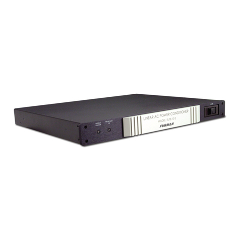
IKONIX apt 400XAC Series User manual

400XAC Series
Modular AC Power Source
Operation Manual for Models
430XAC
460XAC
PART # 39469 Ver. 1.12
January 04th, 2021

DECLARATION OF CONFORMITY
Manufacturer: Associated Power Technologies, Inc.
Address: 28105 N Keith Drive
Lake Forest, IL 60045
Product Name: 400XAC Power Source
Model Number: 430XAC & 460XAC
Conforms to the following Standards:
Safety: EN 61010-1:2010
EMC: EN 61326-1:2013 Class A, IEC 61000-3-3:2008, IEC 61000-3-11:2000, IEC
61000-3-12:2011, EN 61326-1:2013, IEC 61000-4-2:2008, IEC 61000-4-
3:2006+A1:2007+A2:2010, IEC 61000-4-4:2004+A1:2010, IEC 61000-4-
5:2005, IEC 61000-4-6:2008, IEC 61000-4-8:2009, IEC 61000-4-11:2004,
IEC 61000-4-34:2005+A1:2009
Supplementary Information
The product herewith complies with the requirements of the Low Voltage Directive 2014/35/EU,
the EMC Directive 2014/30/EU. and the RoHS Directive 2011/65/EU with respect to the
following substances: Lead (Pb), Mercury (Hg), Cadmium (Cd), Hexavalent chromium (Cr (VI)),
Polybrominated biphenyls (PBB), Polybrominated diphenyl ethers (PBDE), Deca-BDE included.
Last two digits of the year in which the CE marking was affixed: 13
The technical file and other documentation are on file with Associated Power Technologies, Inc.
______________________________
Joseph Guerriero, President
Associated Power Technologies, Inc.
Lake Forest, IL USA, July 20, 2017

i
Table of Contents
1. Introduction....................................................................................................1
1.1 Warranty.................................................................................................1
1.2 Glossary of Terms...................................................................................2
1.1. Safety Symbols ..........................................................................................4
1.3 Safety Precautions .................................................................................4
1.4 Service and Maintenance.......................................................................5
2. Getting Started...............................................................................................6
2.1 Unpacking and Inspection ......................................................................6
2.2 Input/Output Power Considerations........................................................6
2.3 Instrument Power Switch........................................................................8
2.4 Selecting the Appropriate Wire Gauge....................................................8
2.5 Power Cable...........................................................................................9
2.6 Supplied Input Accessories (460XAC)..................................................13
2.7 Environmental Conditions.....................................................................13
2.8 Packaging.............................................................................................14
3. Specifications and Controls .........................................................................15
3.1 Specifications .......................................................................................15
Measurement Considerations..........................................................................27
3.2 Instrument Controls ..............................................................................29
3.2.1 Front Panel Controls......................................................................29
3.2.2 Rear Panel Controls......................................................................31
3.2.3 Soft Keys.......................................................................................32
4. Programming Instructions............................................................................34
4.1 Powering on the Instrument..................................................................34
4.1.1 Set Screen Description..................................................................35
4.1.2 Security .........................................................................................36
4.1.3 Lock...............................................................................................37
4.1.4 Mem Lock......................................................................................37
4.2 System Parameters Description...........................................................38
4.3 Editing System Parameters..................................................................40
4.3.1 Editing Auto Run Mode..................................................................41
4.3.2 Editing Out Mode...........................................................................42
4.3.3 Editing Single Step (PROGRAM Mode only).................................43
4.3.4 Editing Alarm .................................................................................43
4.3.5 Editing Contrast.............................................................................44
4.3.6 Editing Power Up...........................................................................44
4.3.7 Editing Loop Cycle (PROGRAM Mode only) .................................45
4.3.8 Editing V Hi-Lmt & V Lo-Lmt (MANUAL Mode only)......................46
4.3.9 Editing F Hi-Lmt & F Lo-Lmt (MANUAL Mode only) ......................47
4.3.10 Editing Start and EndAngle (MANUAL Mode only).......................48
4.3.11 Editing Results ..............................................................................48
4.3.12 Editing Transient (MANUAL Mode only)........................................49

ii
4.3.13 Editing OC Fold.............................................................................50
4.3.14 Editing Lock...................................................................................50
4.3.15 Editing Mem Lock..........................................................................51
4.3.16 Editing Volt Sense .........................................................................52
4.3.17 Editing Ext Trig ..............................................................................52
4.3.18 Editing Function.............................................................................53
SmartConfig ..................................................................................53
4.4 Using Memories and Steps (PROGRAM Mode only) ...........................55
4.4.1 Selecting a Memory.......................................................................55
4.4.2 Naming a Memory.........................................................................57
4.4.3 Selecting a Step ............................................................................58
4.5 Test Parameters Description.................................................................58
4.6 Editing Test Parameters........................................................................62
4.6.1 Editing Start and EndAngle (PROGRAM Mode only) ...................64
4.6.2 Editing the Memory Cycle (PROGRAM Mode only) ......................65
4.6.3 Editing the Memory (PROGRAM Mode only) ................................66
4.6.4 Editing the Step (PROGRAM Mode only)......................................66
4.6.5 Editing Voltage ..............................................................................67
4.6.6 Editing Frequency..........................................................................68
4.6.7 Editing Transient * (PROGRAM Mode only)..................................68
4.6.8 Editing Trans-Volt* (PROGRAM Mode only)..................................69
4.6.9 Editing Trans-Site* (PROGRAM Mode only) .................................70
4.6.10 Editing Trans-Time* (PROGRAM Mode only)................................71
4.6.11 Editing Trans-Cycle* (PROGRAM Mode only)...............................71
4.6.12 Editing Ramp Up (PROGRAM Mode only)....................................73
4.6.13 Editing Timer Unit (PROGRAM Mode only)...................................74
4.6.14 Editing Delay (PROGRAM Mode only)..........................................74
4.6.15 Editing Dwell (PROGRAM Mode only) ..........................................75
4.6.16 Editing Ramp Down (PROGRAM Mode only) ...............................76
4.6.17 Editing Step Cycle (PROGRAM Mode only)..................................76
4.6.18 Editing A Hi-Lmt & A Lo-Lmt (PROGRAM Mode only)...................77
4.6.19 Editing P Hi-Lmt & P Lo-Lmt (PROGRAM Mode only) ..................78
4.6.20 Editing Ap Hi-Lmt & Ap Lo-Lmt (PROGRAM Mode only)...............79
4.6.21 Editing CF Hi-Lmt & CF Lo-Lmt (PROGRAM Mode only)..............80
4.6.22 Editing PF Hi-Lmt & PF Lo-Lmt (PROGRAM Mode only)..............81
4.6.23 Editing VA Hi-Lmt & VALo-Lmt (PROGRAM Mode only) ..............82
4.6.24 Editing Q Hi-Lmt & Q Lo-Lmt (PROGRAM Mode only)..................83
4.6.25 Editing Prompt...............................................................................84
4.6.26 Editing Connect.............................................................................85
4.6.27 Editing Phase Set..........................................................................86
4.7 Reviewing Test Results.........................................................................86
5. Test Modes ..................................................................................................88
5.1 Description of Test Modes ....................................................................88
5.2 Initializing a Test in PROGRAM Mode..................................................88
5.2.1 AC Output......................................................................................88
5.2.2 DC Output .....................................................................................90

iii
5.3 Initializing a Test in MANUAL Mode......................................................91
5.3.1 AC Output......................................................................................91
5.3.2 DC Output .....................................................................................92
6. Displayed Messages....................................................................................94
6.1 OTP –Over Temperature Protection ....................................................94
6.2 OCP –Over Current Protection............................................................94
6.3 OPP –Over Power Protection..............................................................94
6.4 OVP –Output Voltage Protection .........................................................95
6.5 A-SH –Amplifier Shutdown Protection .................................................95
6.6 RCP –Reverse Current Protection.......................................................95
6.7 LVP –Low Voltage Protection...............................................................95
Displayed if the power source detects a discrepancy between the output
voltage setting of 10V or greater for more than 1 sec. The LED indicator the
Test/Reset key will be blinking.........................................................................95
7. Remote PLC................................................................................................96
7.1 Signal Output........................................................................................96
7.2 Signal Input and Remote Interlock........................................................96
8. Bus Remote Interface USB/GPIB/RS-232...................................................99
8.1 USB/RS-232 Interface..........................................................................99
8.1.1 RS-232 Connector.......................................................................100
8.1.2 Communication Port Configuration..............................................100
8.1.3 Sending and Receiving Commands ............................................100
8.2 GPIB Interface....................................................................................101
8.2.1 GPIB Connector ..........................................................................101
8.2.2 GPIB Address..............................................................................101
8.3 Interface Functions.............................................................................101
8.4 USB/GPIB/RS-232 Interface Command List.......................................102
8.4.1 Basic Commands and Query Commands ...................................102
8.4.2 3Φ4W Queries.............................................................................107
8.4.3 1Φ3W Queries.............................................................................109
8.4.4 Program Commands and Companion Queries............................110
8.4.5 System Commands and Companion Queries .............................113
8.4.6 IEEE 488.2 Common Commands................................................114
9. Calibration Procedure................................................................................118
9.1 Hardware Verification and Calibration Procedure...............................118
Required Measurement Standard. ................................................................118
Required Measurement Equipment...............................................................118
9.2. Activate Non-Calibration Mode...............................................................118
9.3. Adjust the Power Voltage for Control Circuit...........................................118
9.4. Adjust the Amplifier Inverter DC Bus Voltage..........................................119
9.5. Clear the Output High Frequency Ripple and Noise...............................119
9.6. Adjust the Output “0” Volts and “110” Volts DC Offset ............................119
9.7 Software Calibration Procedure..........................................................121
9.8 Enter Calibration Mode.......................................................................122
9.9 Calibration of Voltage 150.0V .............................................................122
9.10 Calibration of Voltage 300.0V.............................................................123

iv
9.11 Calibration of High and Low Current Range.......................................124
9.12 Calibration of Peak Current ................................................................125
10. Options .......................................................................................................126
10.1 Opt. 03 –GPIB Card ..........................................................................126
10.2 Opt. 06 –Ethernet Card......................................................................126
10.3 Ethernet Card Setup...........................................................................127
10.3.1 Saving New Settings ...................................................................129
10.3.3 Power Up.....................................................................................129
10.3.4 Ethernet Card Menu....................................................................131
10.3.5 IP Setup.......................................................................................131
10.3.6 IPAddress...................................................................................132
10.3.7 Gateway IP..................................................................................132
10.3.8 Subnet Mask ...............................................................................132
10.3.9 Device Name...............................................................................133
10.3.10 MAC Address...........................................................................134
10.3.11 Barcode Input ..........................................................................134
10.3.12 Autostart ..................................................................................136
10.3.13 Ethernet Card Settings Commands and Companion Queries..138
10.3.14 Ethernet Card Settings Command Wait Times.........................139
11. Service and Maintenance ..........................................................................140
12. Replacement Parts List..............................................................................141

1
1. Introduction
1.1 Warranty
Ikonix USA, certifies that the power source listed in this manual meets or
exceeds published manufacturing specifications. This power source was
calibrated using standards that are traceable to the National Institute of
Standards and Technology (NIST).
Your new power source is warranted to be free from defects in workmanship and
material for a period of (5) years from date of shipment. We aim to provide an
amazing experience and quality power sources that last a long time. If you’re not
satisfied with your power source, return it within 45 days for a full refund.
Calibrate annually with us, or one of our authorized partners, and we’ll extend
your warranty an additional year for the service life of your power source, and at
least five years after discontinuation. If it breaks during that time, we promise to
fix it for free (unless abuse or excessive damage is present). When your power
source reaches the end of its service life, we’ll responsibly recycle it and give you
a discount on a replacement. Annual calibration and inspection must be made in
each successive year starting one year after the original purchase date in order
to remain eligible for extended warranty coverage beyond the standard warranty
period (five years).
Ikonix USA recommends that your power source be calibrated on a twelve-month
cycle. A return material authorization (RMA) must be obtained from Ikonix USA.
To obtain an RMA please contact our Customer Support team at 1-847-367-4378
or visit aptsources.com. Damages sustained as a result of improper packaging
will not be honored. Transportation costs for the return of the power source for
warranty service must be prepaid by the customer. Ikonix USA will assume the
return freight costs when returning the power source to the customer. The return
method will be at the discretion of Ikonix USA.
Except as provided, herein Ikonix USA makes no warranties to the purchaser of
this power source and all other warranties, expressed or implied (including,
without limitation, merchantability or fitness for a particular purpose), are hereby
excluded, disclaimed and waived.
Any non-authorized modifications, tampering or physical damage will void your
warranty. Elimination of any connections in the earth grounding system or
bypassing any safety systems will void this warranty. This warranty does not
cover accessories not of Ikonix USA manufacture. Parts used must be parts that
are recommended by Ikonix USA as an acceptable specified part. Use of non-
authorized parts in the repair of this power source will void the warranty.
*5 year warranty is valid on any model purchased in 2021 or after.

2
1.2 Glossary of Terms
Alternating Current (AC) - current that reverses direction on a regular basis
(usually 60 times per second in the United States). Measured in amps.
AC Power Source - An instrument that takes one AC voltage and frequency
level and converts it into another AC voltage and frequency level.
Amplifier - a circuit that boosts an input signal from one level to another.
Apparent Power - The total power generated or consumed by a device due to
real and reactive circuit components. Measured in VA (volt-amps).
Calibration - the process of comparing an unknown value with a reference
standard and reporting the results. For example: Applied = 1.30V, Indicated =
1.26V (or Error= -0.04V). Calibration may include adjustment to correct any
deviation from the value of the standard.
Crest Factor - The ratio of peak current (Apeak) to RMS current (Arms).
Complex Power –the vector sum of the real and reactive power components of
a circuit. Measured in VA (volt-amps).
Direct Current (DC) - current that only flows in one direction. Direct current
comes from a polarized source, meaning one terminal is always at a higher
potential than the other. Measured in amps.
Frequency - The number of times a waveform completes a cycle in a period of
time. Measured in hertz.
Inrush Current - A term used to describe the current needed to power a load
upon start-up. Some loads require a large/inrush starting current in order to
operate.
Linear Power Source - a power source that uses a simple amplifier to linearly
increase the amplitude of the output waveform.
Modular - capability that allows the operator to interconnect multiple power
sources in order to increase the power output or power configuration beyond that
of a single instrument.
OC Fold - Over current fold back is a technology used in power sources that
keeps output current constant by reducing the voltage in order to power loads
that may have a high inrush current.

3
PFC - Power Factor Correction is a method by which an inductance is inserted
into the input circuit of a power source to improve the power factor and overall
efficiency of the system.
Phase Angle - the degree of measurement that corresponds to anAC
waveform’s amplitude. Measured from 0 – 360 degrees.
PLC - Programmable Logic Control is an automation method using relay or
digital technology.
Polyphase Mode –the 400XAC AC power sources can be configured to provide
output voltages of up to 600VAC (output configured for 1Φ3W) or provide 3Φ
output power (output configured for 3Φ4W).
Power - A generic term used to describe electrical work being done. There are
many types of power, including real power, reactive power, apparent power, and
complex power.
Power factor - The ratio of real power (watts) to apparent power (VA). Based on
a scale from 0 to 1 to determine how reactive and resistive a load is.
Reactive Power –the power absorbed by capacitive or inductive elements in a
circuit. This power does no work. Measured in VAR (volt-amps reactive).
Real Power –the power that performs work in a circuit. Measured in watts.
Response Time - The time that is needed to regulate the voltage, current,
frequency, and power output when a load is added to the power source.
Safety Agency Listing - A safety mark given to a product that has met stringent
benchmarks as classified by the authorized agency.
SmartConfig –This feature allows the operator to change the output of AC
power source’s Polyphase (3Ø4W) mode to single phase (1Ø2W and 1Ø3W) or
DC mode with a simple button push. Changing the internal cables or dip switches
is not required.
Steady State Current - A term used to describe the current when the load is
running nominally after the inrush current.
Switching Power Source - A power source that uses switching technology
(integrated circuits and components) in order to generate the output waveform.

4
Total Harmonic Distortion (THD) - A percentage that is used to identify the
degree of the noise/unclean signal in a power source’s output waveform.
Transient - a momentary change (spike or dip) in a voltage or current waveform
that can affect the performance of the DUT.
Verification - comparison of measured results against a specification, usually the
manufacturer's published performance figures for the product (e.g. Error = -0.04V,
Spec = ±0.03V, result: "FAIL").
Voltage - The amount of force that is needed to move current from point to point.
Measured in volts.
1.1. Safety Symbols
1.3.1 Product Marking Symbols
Product will be marked with this symbol when it is necessary to refer to
the operation and service manual in order to prevent injury or
equipment damage.
Product will be marked with this symbol when hazardous voltages may
be present.
Product will be marked with this symbol at connections that require
earth grounding.
1.3.2 Caution and Warning Symbols
Calls attention to a procedure, practice, or condition that
could possibly cause bodily injury or death.
Calls attention to a procedure, practice, or condition that
could possibly cause damage to equipment or permanent
loss of data.
1.3 Safety Precautions
•This product and its related documentation must be reviewed for
familiarization with safety markings and instructions before operation.

5
•Before applying power verify that the instrument is set to the correct line
voltage and the correct fuse is installed
To prevent accidental injury or death, these safety
procedures must be strictly observed when handling
and using the test instrument.
1.4 Service and Maintenance
User Service
To prevent electric shock do not remove the instrument cover. There are no user
serviceable parts inside. Routine maintenance or cleaning of internal parts is not
necessary. Any external cleaning should be done with a clean dry or slightly
damp cloth. Avoid the use of cleaning agents or chemicals to prevent any foreign
liquid from entering the cabinet through ventilation holes or damaging controls
and switches, also some chemicals may damage plastic parts or lettering. Any
replacement cables and high voltage components should be acquired directly
from APT or its distributors.
Service Interval
The instrument must be returned at least once a year to anAPT authorized
service center for calibration and inspection of safety related components. APT
will not be held liable for injuries suffered if the instrument is not properly
maintained and safety checked annually.
User Modifications
Unauthorized user modifications will void your warranty. APT will not be
responsible for any injuries sustained due to unauthorized equipment
modifications or use of parts not specified by APT. Instruments returned to APT
with unsafe modifications will be returned to their original operating condition at
the customer’s expense.

6
2. Getting Started
This section contains information for the unpacking, inspection, preparation for
use and storage of your APT product.
2.1 Unpacking and Inspection
Your instrument was shipped in a protective shipping carton designed to protect
the instrument through the shipping process. If the shipping carton is damaged,
inspect the contents for visible damage such as dents, scratches, or broken
display. If the instrument is damaged, notify the carrier and APT’s customer
support department. Please save the shipping carton and packing material for
the carrier’s inspection. Our customer support department will assist you in the
repair or replacement of your instrument. Please do not return your product
without first notifying us.
Safe Lifting and Carrying Instructions
Proper methods of lifting and carrying can help to protect against injury. Follow
the recommendations below to ensure that instruments are handled in a safe
manner.
•Determine if the instrument can be lifted by one individual or requires
additional support.
•Make sure that your balance is centered and your feet are properly
spaced, shoulder width apart behind the instrument.
•Bend at the knees and make sure your back is straight.
•Grip the instrument with your fingers and palms and do not lift unless your
back is straight.
•Lift up with your legs, not your back.
•Keep the instrument close to your body while carrying.
Lower the instrument by bending your knees. Keep you back straight.
2.2 Input/Output Power Considerations
Special care should be taken when making connections to the input and output
terminal blocks located on the rear panel of the 400XAC. Ensure that the
appropriate wire gauges are used to assemble a satisfactory line cord. Failure to
assemble a quality line cord could result in fire or personal injury. Refer to the
following graphs for input/output power requirements:

7
0
500
1000
1500
2000
2500
3000
3500
4000
4500
0 500 1000 1500 2000 2500 3000 3500
430XAC
0
1000
2000
3000
4000
5000
6000
7000
8000
9000
0 1000 2000 3000 4000 5000 6000 7000
460 XAC
Input/VA
Input/VA
Output/VA
Output/VA

8
2.3 Instrument Power Switch
The power switch that is included in the instrument is not considered a
disconnecting device. It only disconnects one current carrying conductor to
power off the device. The user should configure the equipment with an external
switch or circuit breaker for disconnecting it from each operating energy supply
source. In compliance with EN61010-1 for permanently connected equipment
this switch should meet the following guidelines.
a.) It shall be included in the building installation.
b.) It shall be in close proximity to the equipment and within easy reach of
the operator.
c.) It shall be marked as the disconnecting device for the equipment
d.) It shall not interrupt the protective earth conductor.
2.4 Selecting the Appropriate Wire Gauge
Below is a table which provides recommended appropriate wire gauges for the
400XAC.
430XAC Input
L
N
G
12AWG
12AWG
14AWG
430XAC Output
Phase
A
B
C
N
G
As
Bs
Cs
Ns
1Ø2W
10AWG
-
-
10AWG
12AWG
18AWG
-
-
18AWG
1Ø3W
14AWG
14AWG
-
14AWG
14AWG
18AWG
18AWG
-
18AWG
3Ø4W
14AWG
14AWG
14AWG
14AWG
14AWG
18AWG
18AWG
18AWG
18AWG
DC
14AWG
-
-
14AWG
14AWG
18AWG
-
-
18AWG
460XAC Input
Phase
A-L
B-L
C-L
A-N
B-N
C-N
G
1Ø2W
10AWG (A-L/B-L/C-L short)
10AWG (A-N/B-N/C-N short)
12AWG
3Ø3W
12AWG
12AWG
12AWG
A-L/A-N
short
B-L/B-N
short
C-L/C-N
short
10AWG
3Ø4W
16AWG
16AWG
16AWG
10AWG (A-N/B-N/C-N short)
10AWG
460XAC Output
Phase
A
B
C
N
G
As
Bs
Cs
Ns
1Ø2W
8AWG
-
-
8AWG
10AWG
18AWG
-
-
18AWG
1Ø3W
14AWG
14AWG
-
14AWG
16AWG
18AWG
18AWG
-
18AWG
3Ø4W
14AWG
14AWG
14AWG
14AWG
16AWG
18AWG
18AWG
18AWG
18AWG
DC
10AWG
-
-
10AWG
10AWG
18AWG
-
-
18AWG

9
2.5 Power Cable
Before connecting power to this instrument, the protective
ground (earth) terminals of this instrument must be
connected to the protective conductor of the line (mains)
power cord. The main plug shall only be inserted in a socket outlet (receptacle)
provided with a protective ground (earth) contact. This protective ground (earth)
must not be defeated by the use of an extension cord without a protective
conductor (grounding).
The mains plug is used as the disconnecting device and
shall remain readily operable. The socket-outlet shall be
installed. Near the equipment and shall be easily
accessible.
The main plug shall only be inserted in a socket outlet with
a protective ground (earth) contact. This protective ground
must not be defeated by the use of an extension cord
without a protective conductor.
Do not replace the power supply cord with an improperly
rated cord. For North American:A UL listed and CSA
labeled power cord must be used with the instrument in the
United States and Canada. The power cord must include a NEMA5-15 style male
plug, SVT or SJT cord sets, and be rated for at least 125VAC, 10A, number 16
gauge (or 125VAC, 15A, number 14 gauge) wire or larger, and the length of the
cord does not exceed 2 m must be used. For European:A certified power supply
cord not lighter than light PVC sheathed flexible cord according to IEC 60227,
designation H03 VV-F or H03 VVH2-F (for equipment mass not exceeding 3 kg),
or H05 VV-F or H05 VVH2-F2 (for equipment mass exceeding 3 kg), and be
rated for at least 3G 0.75 mm² (for rated current up to 10 A) or 3G 1.0mm² (for
rated current over 10A up to 16 A) wire or larger, and the length of the cord does
not exceed 2 m must be used.
400XAC Input Power Considerations
The 400XAC can be powered with several different input power configurations.
Refer to the diagram below for connecting a single phase, 3 phase wye, and 3
phase delta power source to the instrument:

10
400XAC Output Power Considerations
Figure 1: Input/Output Terminal Block and Output Connection Description
L1
L2
L3
N1
N2
N3
L N
1P2W
L1
N1
L2 N2
L3
N3
A
B
C
3P3W
L1
N1
L2
N2
L3
N3
A
BC
N
3P4W
AC IN
L3
G
N2
AC IN
L2
G
N3
PFC1
360XAC
N1
L1
AC IN
G
PFC3
PFC2
L
1P2W
N3
L1
GN2
L2L3
G N
N1
N3
C
L3
G
3P3W
L1
N1
L2
N2
BAG
L2
N
L3
N1
B
G
N2
L1
N3
A
G
3P4W
C
Power System Rear Panel
460XAC

11
Figure 2: 3Ø4W Configuration (Wye Load)
Figure 3: 3Ø3W Configuration (Delta Load)

12
Figure 4: 1Ø2W Configuration
Figure 5: 1Ø3W Configuration

13
Figure 6: DC Output Configuration
2.6 Supplied Input Accessories (460XAC)
Accessory:
1P2W
3P3W
3P4W
Shorting Bar 39177
-
3
-
Shorting Bar 39178
1
-
1
Shorting Bar 39179
1
-
-
Screw 39243
2
-
1
2.7 Environmental Conditions
Operating Environment
Temperatures: 5º - 40º C (41º - 104º F)
Relative humidity: 20% - 80%
Altitude: 2,000 meters (6,562 feet)
Do not block any ventilation openings to prevent over
heating of the equipment. Keep the ventilation slits
uncovered during operation. Failure to do so could cause
the instrument to overheat and may damage internal

14
components.
The instrument should also be protected against temperature extremes which
may cause condensation within the instrument.
If the instrument is used in a matter not specified by the manufacturer, the
protection provided by the instrument may be impaired.
Storage and Shipping Environment
This instrument may be stored or shipped in environments with the following
limits:
Temperature………………..-40º to +55º C
Altitude…………………….7,620 meters (25,000 feet)
2.8 Packaging
Please enclose the instrument with all options, accessories and test leads. All
returns must be accompanied by a return material authorization (RMA) number
which is provided by the customer support department. Failure to ship your
instrument without a RMA number will result in additional fees for handling and
storage.
APT will not be responsible for any repair costs associated with shipping damage
as a result of improper packaging. The customer is responsible for providing
adequate shipping insurance coverage while shipping an instrument in the event
of loss or damage while in transit.
Standard Accessories
430XAC
460XAC
Interlock Disable Key(1505)
X1
X1
Screw 5*10mm/Machine screw
and washer
N/A
X2
Screw 4*12mm/Flat head cap
screw
X4
X4
Rack Mount (9U)
X2
X2
Handle for rack (3U)
X2
X2
Short Bar for Terminal Assembly
SB-10
A-61060-COP1-A X3
A-61060-COP2-A X1
A-61060-COP3-A X1
A-61060-COP4-A X1
USB Cable
X1
X1
This manual suits for next models
2
Table of contents
