INDUSTRIAL MAID AZTech T3500 User manual
1
Owners Manual
AZTech Model T3500/T4500
INDUSTRIAL AIR CLEANER
Contents
Safety/Inspection ...................................................... 2
Specications............................................................ 3
Installation................................................................. 4
Replacement Parts ................................................... 6
Electrical ................................................................... 7
Troubleshooting/Notes.............................................. 13
Warranty ................................................................... 18

2
SAFETY
PLEASE READ THE FOLLOWING INSTRUCTIONS CAREFULLY BEFORE INSTALLING,
OPERATING OR SERVICING YOUR AIR CLEANER.
Follow all building and safety codes when installing this equipment. Pertaining but not limited to,
the Occupational Safety and Health Act (OSHA), National Electric Code (NEC), Uniform Building
Code (UBC), National Fire Prevention Act (NFPA) & all state and local codes.
A qualied electrician should perform all electrical connections.
Keep Flammable Objects away from the air cleaner and under no condition should a burning
object be allowed into the air cleaning system.
Take proper caution in placing units in buildings with radiant heaters installed. Follow the radiant
heater manufacturer’s guidelines for clearance to combustibles.
Do not mix materials collected in your Air Cleaner. The captured materials could create a
hazardous environment or a condition of operation for which the equipment is not intended. The
Manufacturer is relieved of any liability if the unit is not operated according to this manual.
Do not use the Air Cleaner for an application other than for which it was intended. Consult your
distributor, Applicable Codes, or call Industrial Maid for application assistance.
A re suppression system is not included. Please consult your local re protection specialist for
any required extinguishing equipment.
Consult with your insurance underwriter about any other protection from re damages.
The Manufacturer reserves the right to make design changes, which may improve the air cleaner.
This unit is intended for use to collect ambient smoke, airborne pollutants, and fumes in industrial
and manufacturing facilities. Do not use for the collection of ammable or explosive metals, dust,
fumes, or other potentially hazardous materials.
INSPECTION
Upon receiving your Industrial Maid air cleaner, please inspect for any damage incurred during
shipment. Inspect carefully; some damage may not be noticeable until the unit is installed. Notify
your shipper of any damage immediately. Claims must be led with the shipper within 15 days.
Freight damage claims are the responsibility of the purchaser.

3
Cabinet 14 ga powder coated steel frame. 3/16 polyethylene panels(14 ga steel
panels, optional)
Size 25”H x 72”L x 25”D (single cabinet)
Weight T3500 - 192 lbs.
T4500 - 199 lbs.
Power T3500 208-230/460/3/60 6.0/3.0amps
T4500 208-230/460/3/60 7.6/3.8 amps
Air Volume T3500 - 3,500 CFM
T4500 - 4,500 CFM
Motor T3500 - 2 HP 208-230/460/3/60 TEFC
T4500 - 3 HP 208-230/460/3/60 TEFC
Blower 10 x 10 Belt Drive Forward Curve
Exhaust Four Way adjustable louver
Filters Prelter - (2) 4” Pleats
Main Filter – (2) 24 x 24 x 21, 95%, 10 Pocket Fiberglass Bags
Warranty 3 year limited warranty
SPECIFICATIONS

4
INSTALLATION
The system’s weight must be taken into account when choosing the proper installation method
(see specication). Follow all applicable building and electrical codes.
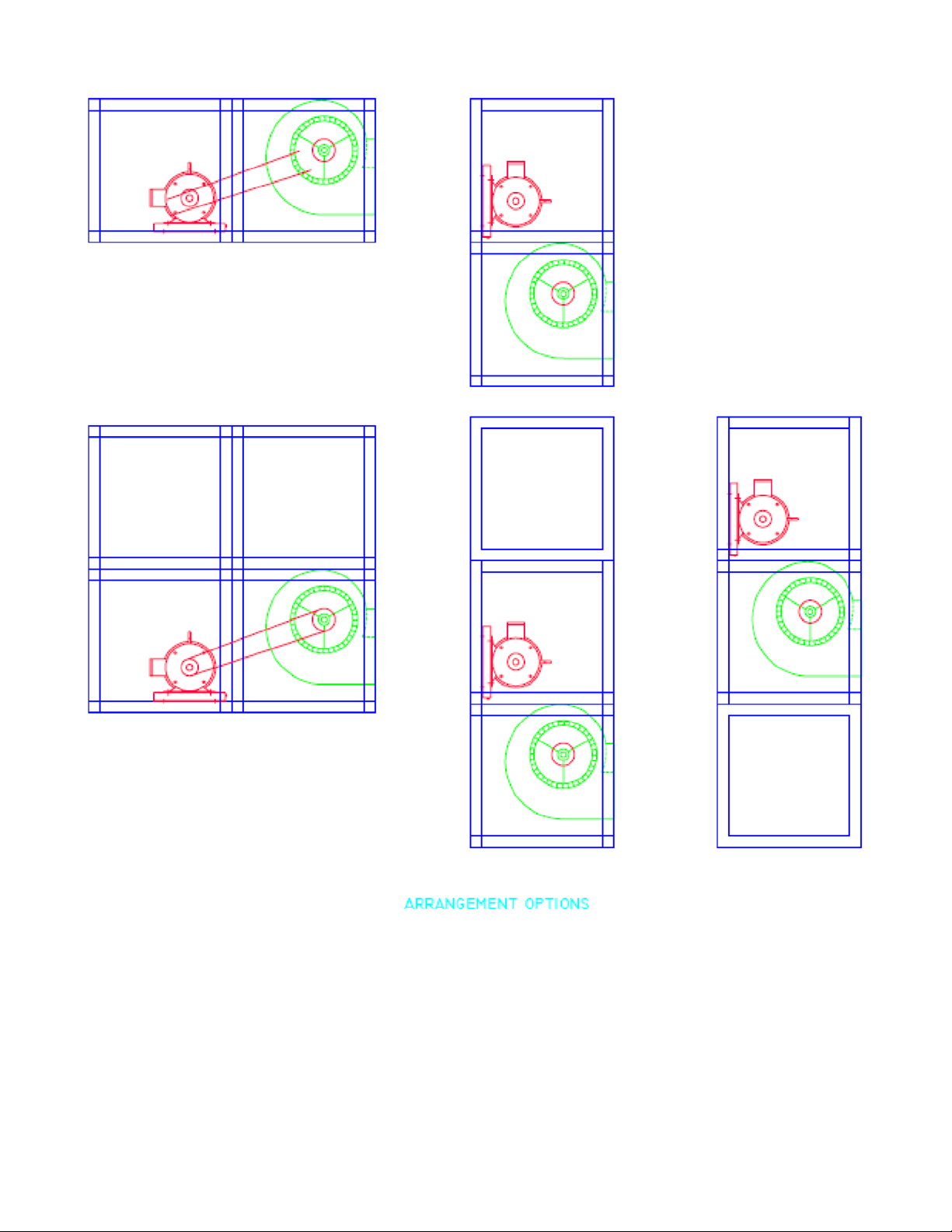
There are three main ways of installing your Model 3500 air cleaner, Chain Hanging (eye bolts
factory installed as option), rod & cradle , or angle braces. Figure 2 illustrates these methods.
Do not chain mount double cabinet units, use (4) 5/8” threaded rod and cradle the collector
(lower right, gure 2).
Figure 1.

5
Mounting materials must be able to support the weight of the air cleaner plus the additional
weight of the material collected. Consult your local building code for proper installation methods
and materials. Failure to use the proper materials could result in injury or damage equipment
and will void the warranty.
Figure 2.
6
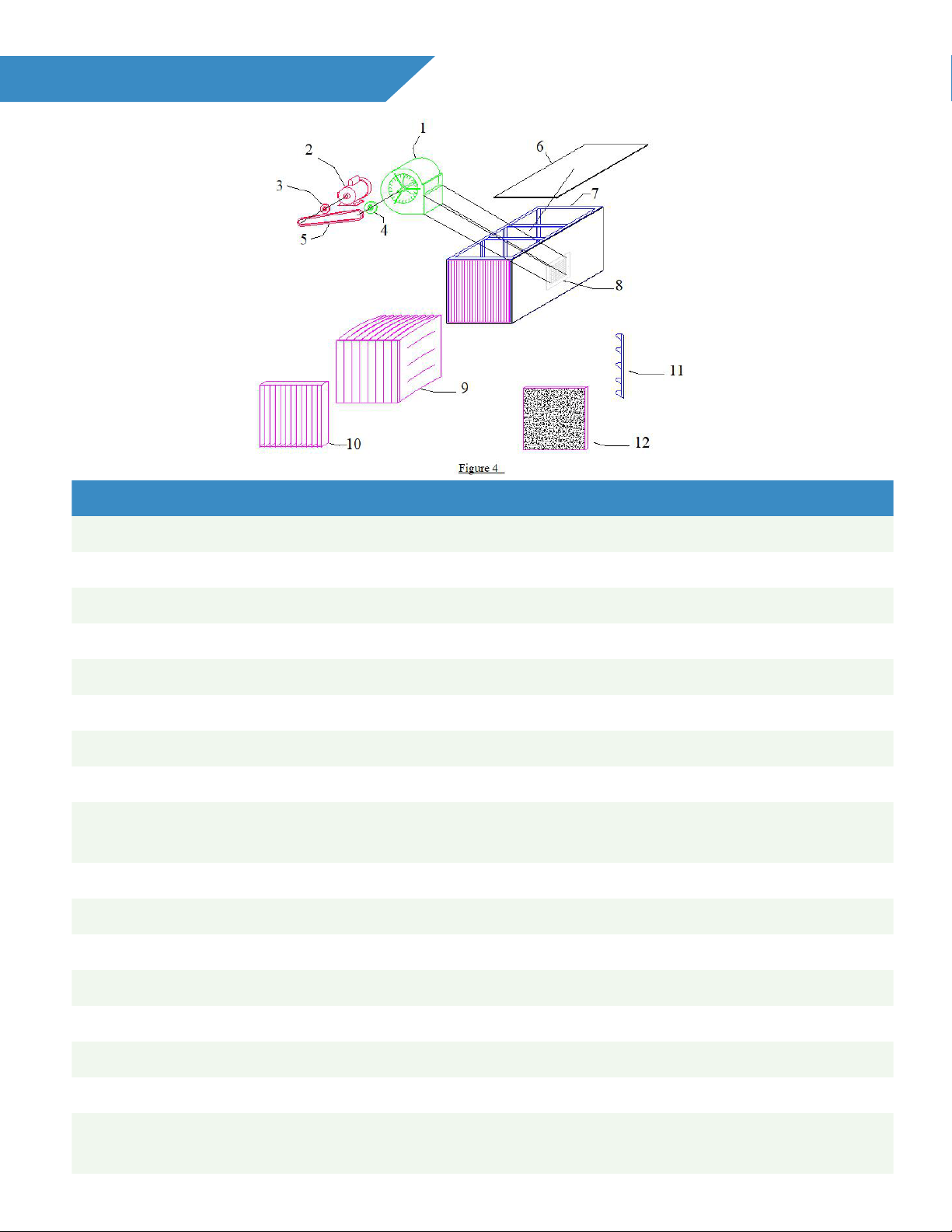
REPLACEMENT PARTS
ITEM PART NUMBER QTY DESCRIPTION
1 BW10-AA10 1 2 & 3 HP BLOWER ASSEMBLY
2A MT02-2431-SG 1 T3500, 2 HP 230/460/3/60 TEFC MOTOR
2B MT03-2433-SG 1 T4500, 3 HP 230/460/3/60 TEFC MOTOR
3 PT78-0035 1 2 & 3 HP DRIVE PULLEY
4A PT34-0005 1 2 HP BLOWER PULLEY, 5” FIXED
4B PT34-0010 1 3 HP BLOWER PULLEY, 10” FIXED
5A PT0A-0040 1 2 HP - A40 DRIVE BELT
5B PT0A-0049 1 3 HP - A49 DRIVE BELT
6A 003500-11PE 3,5 or 7 3/16 POLYETHYLENE PANELS, TOP, BOTTOM,
& BACK
6B 003500-10PE 1 3/16 POLYETHYLENE PANEL, EXHAUST
7 FR35-ASSY 1 14 GA FRAME ASSEMBLY
8 GR07-0013 1 4-WAY ADJUSTABLE EXHAUST GRILLE
9A FB91-2424 2,4,6 or 8 95 % FIBERGLASS BAG FILTER
9B FB61-2424 2,4,6 or 8 65 % FIBERGLASS BAG FILTER
10 FP44-2424 2,4,6 or 8 4” PLEATED PREFILTER
11 FD02-2727 2 2” POLY PAD PREFILTER - OPTIONAL
12 253560-PFHK 2 POLY PAD PREFILTER MOUNTING HOOK -
OPTIONAL

7
ELECTRICAL WIRING
Unit comes wired to a junction box Additional wiring will be required to get power to unit, which is
not supplied with this product.
Motor Starters, disconnect, wiring, overloads, and thermal protection are NOT provided by the
Manufacturer
All Field wiring should be performed by a qualied electrician and must meet all local, NFPA and
NEC codes. Failure to install the proper electrical wiring, thermal protection, and controls will
void the warranty.
After completion of the eld wiring, turn the unit on to check for proper rotation. Rotation is
marked on the side of the blower housing. Backward rotation will result in a much lower air ow,
louder noise, and will over amp the motor. Check the motor nameplate before switching wires
and reversing rotation, to ensure the unit is operating at or below rated amp draw.
8

9
Motor 25 to 50 Feet 100 Feet 150 to 200 Feet
HP 200V 230V 460V 200V 230V 460V 200V 230V 460V
1/3 14 14(16)* 14(18)* 12 12 14(18)* 8 10 14(18)*
1/2 14 14(16)* 14(18)* 12 12 14(18)* 8 10 14(18)*
3/4 14 14(16)* 14(18)* 12 12 14(18)* 8 10 14(18)*
1 14 14(16)* 14(18)* 12 12 14(18)* 8 10 14(16)*
1 1/2 12 14 14(18)* 10 10 14(16)* 6 8 14
2 12 12 14(18)* 8 10 14(16)* 6 6 12
3 10 12 14(18)* 6 8 14 4 6 12
5 8 10 14(16)* 4 6 12 2 4 10
7 1/2 6 8 14 4 4 10 1 2 8
10 6 6 12 3 4 10 1/0 1 6
15 4 4 10 1 2 8 3/0 2/0 4
20 3 4 10 1/0 1 6 4/0 3/0 4
25 2 3 8 2/0 1/0 6 250kcmil 4/0 3
30 1 3 8 3/0 1/0 6 300kcmil 4/0 3
40 1/0 1 8 4/0 3/0 4 400kcmil 300kcmil 1
50 2/0 1 6 250kcmil 3/0 3 500kcmil 350kcmil 1
60 3/0 1/0 6 300kcmil 4/0 3 600kcmil 400kcmil 1/0
75 4/0 2/0 4 350kcmil 250kcmil 2 700kcmil 500kcmil 2/0
100 250kcmil 3/0 4 500kcmil 350kcmil 1 900kcmil 700kcmil 3/0
125 300kcmil 4/0 3 600kcmil 400kcmil 1/0 1250kcmil 800kcmil 4/0
150 350kcmil 250kcmil 2 700kcmil 500kcmil 2/0 1500kcmil 900kcmil 250kcmil
200 500kcmil 350kcmil 1/0 1250kcmil 800kcmil 4/0 1750kcmil 1250kcmil 350kcmil
250 600kcmil 400kcmil 2/0 1500kcmil 900kcmil 250kcmil 2000kcmil 1500kcmil 400kcmil
MOTOR MOUNTING
Motor must be securely fastened to a rigid, at surface to prevent vibration and minimize noise.
For secure mounting use high-quality bolts of the largest possible diameter.
Belt-drive sheaves must be in-line. Use a straight edge to check. Do not over-tighten belts.
Direct coupled installations require a careful check of shaft and coupling alignment, shaft offset
and/or angular misalignment should be less than .002”. Shim motor base as necessary. Do not
depend on a exible coupling to compensate for misalignment.
Table A - Minimum Wire Sizes for 3- Phase Motors
NOTE: kcmil denotes thousand circular mils. AWG sizes formerly given in MCM.
(*) Type S, SO, SJ, SJO, etc. exible cable wire sizes. See NEC article 400 for ampacity.

10
CONNECTING POWER TO MOTOR
To connect motor for proper voltage and rotation, refer to the connection diagram on the
nameplate or inside the terminal/conduit box.
Motor 25 Feet 50 Feet 100 Feet 150 Feet 200 Feet
HP 115V 230V 115V 230V 115V 230V 115V 230V 115V 230V
1 10 14(16)* 6 12 4 10 2 8 1 6
1 1/2 8 14 6 12 3 8 1 6 1/0 6
2 8 14 4 10 2 8 1/0 6 2/0 4
3 6 12 3 8 1/0 6 2/0 4 4/0 3
5 - 10 - 6 - 4 - 2 - 1
7 1/2 - 8 - 6 - 3 - 1 - 1/0
10 - 8 - 4 - 2 - 1/0 - 2/0
Table B - Minimum Wire Sizes for Single Phase Motors
* Type S, SO, SJ, SJO, etc. Flexible cable wire sizes. See NEC Article 400 for ampacity.
NOTE: NEC Article 310-5 --- Minimum conductor size for general wiring at 115-440VAC is
No. 14AWG.Above wire sizes based on approximate 5% voltage drop during starting; copper
conductors; and 75° C type THHW, THW, THWN, RH, RHW insulation, etc. For aluminum
wire, increase two wire size steps minimum. See NEC Article 310 for ampacities of aluminum
conductors.

11
RECOMMENDED MAINTENANCE
WARNING
All aspects of the installation must conform to the requirements of
the NEC, including Article 430 (Motor circuits and Controllers), and all
local codes.
Wherever possible, each motor should be powered from a separate circuit of adequate capacity
to keep voltage drop to a minimum during starting and running. Increase wire size where motor is
located a distance from the power source. Wire size must be adequate to minimize voltage drop
during starting and running. Refer to Tables A and B for suggested wire sizes. Distances shown
are one-way between source and motor. Portable cords, if used, should be as short as possible
to minimize voltage drop. Long or inadequately sized cords, especially on hard starting loads, can
cause motor failure. All electrical connections in system must be secure to prevent voltage drop
and localized heating.
• Determine direction of rotation before connecting driven equipment to prevent damage.
• To prevent bearing damage, do not strike shafts with hammer or other tool.
• If the motor has been damp or wet, then have motor serviced by a qualied motor repair
shop before operating.
Recommended Maintenance
Remove dirt accumulations in and around vent openings, by vacuuming. Dirt accumulations
can cause motor overheating and a re hazard. Enclosed motors can be cleaned with an air
jet; wear eye protection.
Periodically inspect the installation. Check for dirt accumulations; unusual noises or vibration;
overheating; worn or loose couplings, sheaves and belts; high motor current; poor wiring or
overheated connections; loose mounting bolts or guards; and worn motor starter contacts.
Dayton ball-bearing motors without lubrication provision do not require periodic relubrication.
Where motor has provision for bearing lubrication, lubricate as follows:
1. After stopping motor and disconnection power, thoroughly wipe the housing around both of
the motor bearings, ller and drain plugs (on TEFC) ratings, remove fan cover for access
to plugs).
2. Remove ller and drain plugs and install a 1/8” pipe thread lube tting in ller hole.
3. Using a low pressure grease gun, pump new grease into motor until it appears at the drain
hole.
4. Run motor for several minutes to discharge excess grease. Shut motor OFF, replace ller
and drain plugs, and reinstall fan cover.
See Table C for suggested regreasing intervals.

12
MOTOR HP AT 1800 RPM MAX
TYPE OF SERVICE UNDER 50 50 TO 100 OVER 100
Infrequent operation or light duty in clean atmosphere 2 Years 2 Years 1 Year
8 to 16 hours per day in clean, relatively dry atmosphere 2 Years 1 ½ Years 1 Year
12 to 24 hours per day heavy duty use, or if moisture is
present
1 Year 1 Year 6 months
Heavy duty use in dirty, dusty locations; high ambients;
moisture laden atmosphere; constant vibration
4 Months 4 Months 3 Months
NOTE 1: Motors operating faster than 1800 RPM should be relubricated on a more frequent
maintenance schedule. Use a reputablebrand lithium or synthetic-base grease intended for electric
motor ball bearings. Recommended greases include: Standard Oil of California (Chevron) SRI#2,
and Exxon Corp. PolyRex-EM. Keep grease container clean and covered.
Table C – Suggested Regreasing Intervals

13
MOTOR TROUBLESHOOTING
This chart suggests common answers to electric motor problems. The information is not
all-inclusive and does not necessarily apply in all cases. When unusual operating conditions,
repetitive failures, or other problems occur, consult an electric motor service rm.
Symptom Possible Cause(s) Corrective Action
Motor fails to start 1. Blown fuses 1. Replace with time-delay fuses.
Check for grounded winding
2. Voltage too low at motor
terminals due to line drop
2. Consult local power company.
Increase wire size (refer to
Tables A & B). Check for poor
connections
3. Overload in motor starter tripped 3. Check and reset overload
relay in starter. Check heater
rating against motor nameplate
current rating
4. Overload (internal thermal
protector) tripped
4. Check motor load. If motor
has an automatic or manual
reset thermal protector, check
if tripped
5. Improper line connections 5. Check connections against
diagram supplied with motor
6. Motor may be overloaded 6. Reduce load or increase motor
size
Motor does not come up to
speed or takes too long to
accelerate
1. Not applied properly 1. Consult motor service rm for
proper type. Use larger motor
2. Voltage too low at motor
terminals
2. Increase wire size (refer to
Tables A & B). Check for poor
connections. Check for voltage
unbalance (3-Phase)
3. Starting load to high 3. Check load motor is carrying at
the start
4. Excess loading; tight belts 4. Reduce load; increase motor
size. Adjust belts

14
Symptom Possible Cause(s) Corrective Action
5. Defective motor. 5. Replace or repair
6. Inadequate starting torque. High
inertia load
6. Replace with a larger motor
Motor stalls during
operation
1. Overloaded motor 1. Reduce load or increase the
motor size
2. Low motor voltage 2. Verify that nameplate voltage is
maintained
Motor vibrates or is
excessively noisy
1. Motor shaft is misaligned 1. Realign
2. 3-phase motor running on single
phase
2. Check for open circuit, blown
fuses or unbalanced voltages
3. High or unbalanced voltages 3. Check wiring connections.
Consult local power company
4. Worn, damaged, dirty or
overloaded bearings
4. Replace bearings; check
loading and alignment
5. Defective winding. Bent or
bowed shaft
5. Repair or replace
6. Loose sheave or misaligned
coupling
6. Tighten set screw(s); realign
coupling
Motor overheats while
running under load
1. Overloaded 1. Reduce load; increase motor
size; belts may be too tight
2. Dirt blocking ventilation openings 2. Clean motor
3. If 3-Phase, one phase may be
open
3. Check lines for open phase.
Check voltage with motor
disconnected, one fuse may be
blown.
4. Unbalanced supply voltage 4. Check for faulty connections.
Voltage on all three lines
should be balanced within 1%.
Balance single phase loads.
5. Faulty connection 5. Clean, tighten, or replace
6. High or low voltage 6. Check voltage at motor, should
not be more than 10% above or
below rated
7. Defective motor 7. Repair or replace

15
BLOWER OPERATION
After electrical connections are completed, start motor briey to determine the direction of wheel
rotation. If necessary to reverse the rotation, follow instructions given on the motor nameplate or
terminal box cover.
With air system in full operation, and with all ducts attached and inspection door(s) closed, measure
the current input to the motor and compare with nameplate rating to determine if the motor is
operating under safe load conditions.
Blower Maintenance
1. After electrical connections are completed, start motor briey to determine the direction of
wheel rotation. If necessary to reverse. The rotation, follow instructions given on the motor
nameplate or terminal box cover.
2. Follow motor manufacturer’s instructions for motor lubrication. Remove excess lubricant.
3. Follow Replacement Parts Manual for blower bearing lubrication.
4. Check wiring to make sure it is secure and well insulated
BLOWER TROUBLESHOOTING CHART
Symptom Possible Cause(s) Corrective Action
Excessive noise and/or
vibration
1. Foreign object 1. Remove
2. Wheel rubbing on housing 2. Center the wheel
3. Loose wheel or sheave on
shaft
3. Tighten all set screws
4. Motor or blower not secure 4. Tighten Mounting
5. Belt(s) too loose/too tight 5. Adjust Tension
6. Worn belt(s) 6. Replace
7. Mismatched belt(s) 7. Replace
8. Loose or worn bearings 8. Replace
9. Bearing or drive alignment 9. Realign
10. Accumulation of material on
wheel
10. Clean
11. Motor out of balance 11. Replace
12. Wheel out of balance 12. Replace or Re-balance
13. Sheaves eccentric or out of
balance
13. Replace

16
Symptom Possible Cause(s) Corrective Action
Insufcient air ow 1. Blower speed too low 1. Check for correct drives
2. Dampers or registers closed 2. Open
3. Dirty or clogged lters 3. Clean or replace
4. Leaks in duct work 4. Repair
5. Elbows, cabinet walls, or other
obstructions
5. Correct
6. Belt slippage 6. Adjust or replace
Too much air ow 1. Blower speed too high 1. Check for correct drives
2. Filter(s) not in place 2. Install lter(s)
Unit fails to operate 1. Blown fuse or open circuit
breaker
1. Replace fuse or reset circuit
breaker
2. Broken fan belt 2. Replace
3. Defective motor and/or
capacitor
3. Replace
Motor overloads or overheats 1. Blower speed too high or motor
horsepower too low
1. See Speccations for correct
drives and HP
2. System static pressure too low 2. Check static pressure and
correct syst
3. Shorted windings in motor 3. Replace
17
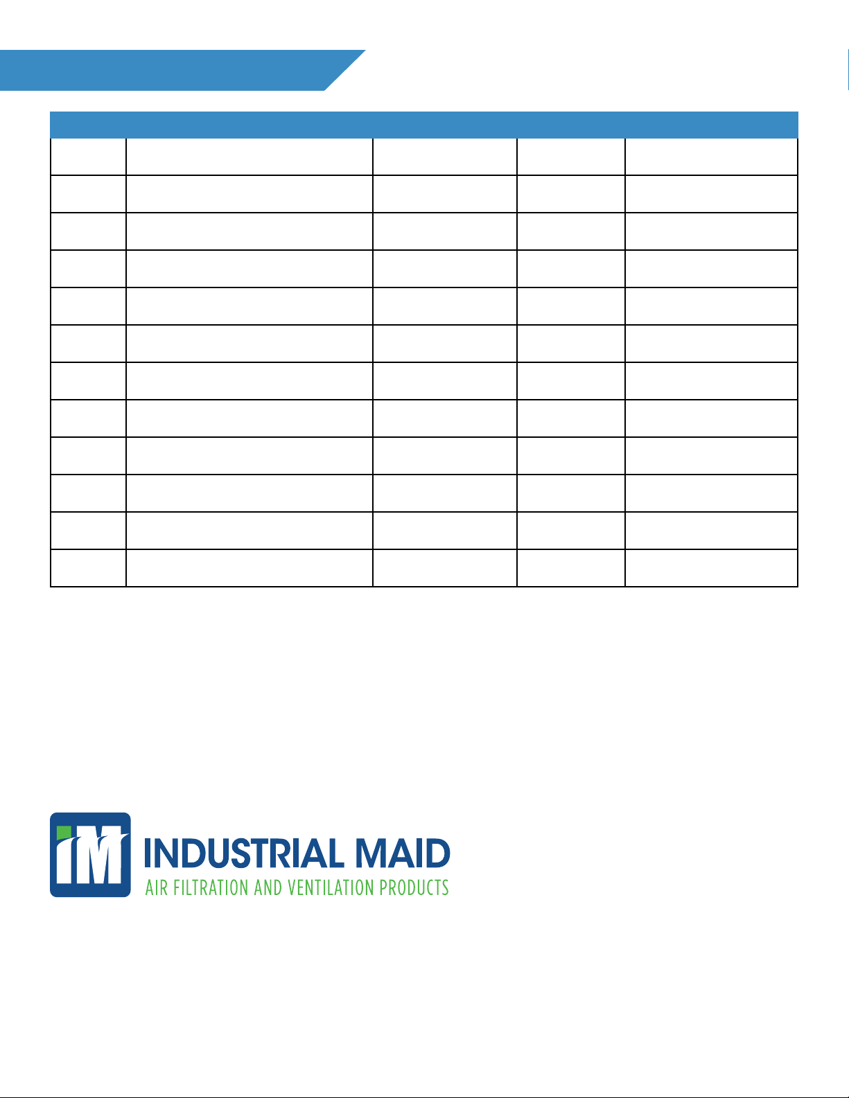
SERVICE RECORD
Date Description Serviced By Location Comments
351 S. 12th Rd.
Cortland, NE 68331
Ph. (402) 798-7116
Fx. (402) 798-7117
www.industrial-maid.com
START UP DATA: (write down for future reference)
MODEL NUMBER____________________________ SERIAL NUMBER_______________________
HP________________________ VOLTAGE____________________MFG. DATE__________________
VOLTAGE - L1_______________________L2________________________L3____________________
AMP DRAW - L1______________________L2________________________L3____________________
OTHER NOTES: ______________________________________________________________________
_____________________________________________________________________________________
PRESSURE GAUGE READING(AT START UP)____________________________________________

18
WARRANTY
1. Limited Product Warranty. Industrial Maid, LLC, 351 S. 12th Rd., Cortland, NE, 68331, hereby
warrants to any owner who has purchased the equipment other than for purposes of resale, as
follows:
A. All components of air cleaners and air ltration equipment manufactured (collectively
“Components”) by Industrial Maid, as well as motors and drives installed on Industrial Maid
units (collectively “Components”) will be manufactured in conformity with stated materials,
dimensions, and tolerances;
B. Components manufactured by Industrial Maid, as well as motors and drives installed in
Industrial Maid units, will, in normal use and service, be free from defects in material and
workmanship for a period of thirty-six (36) months;
C. Components not manufactured by Industrial Maid (other than motors and drives) are not
included within the thirty-six (36) month Warranty. These excluded items include HMI
Control Panels, motor starters, disconnects, lters, duct work, and installation not supplied by
Industrial Maid. The Limited Product Warranty on these items, when sold by Industrial Maid
as part of the unit, is twelve (12) months and parts only.
D. Upon delivery, Industrial Maid will convey good and marketable title to the Components
to Owner free and clear of all liens and encumbrances other than those arising in favor of
Industrial Maid, including the purchase money security interest.
2. Duration of Warranty/Notice Requirements. The warranties set forth in Section1 above shall
apply to covered defects in Components that are discovered by Owner within the respective
thirty-six (36) months or twelve (12) months following the Invoice Date (the “Warranty Period”)
and are reported to Industrial Maid in writing within thirty (30) calendar days following their
discovery (the “Notice Period”).
3. Exceptions and Exclusions. Notwithstanding anything herein to the contrary, the warranties set
forth in Section 1 above do not cover any of the following, each of which are hereby expressly
excluded therefrom:
A. Defects that are not discovered during the Warranty Period;
B. Defects that are not reported to Industrial Maid in writing within the Notice Period;
C. Usual and customary deterioration or wear resulting from normal use, service and exposure;
D. Consumable items such as lters, belts, and lter hammer are not warranted;
E. Any Components that are installed outside of the United States, Canada, or Mexico, United
Kingdom and European Union;
F. Any xtures, equipment, materials, supplies, accessories, parts, or Components that have
been manufactured and/or furnished by any third party;
G. Any shortages in or damage to any Industrial Maid Components at delivery, all of which shall
be exclusively governed by the invoice or Purchase Agreement;
H. The durability and/or variation in the appearance or color of Components;
I. Any Components which have been removed from the Industrial Maid unit on which they were
originally installed;
J. The effect or inuence any Industrial Maid Components may have on any pre-existing or
other structures, including without limitation, any damage associated with loads imposed by
the Industrial Maid Components on such structures;

19
K. Any defect and/or any loss, damage, cost or expense incurred by Owner or any third party to
the extent the same arise out of, relate to or result, in whole or in part, from any one or more
of the following:
i. Damage in transit or in handling;
ii. Theft, vandalism, accident, war, insurrection, re or other casualty;
iii. Incorrect installation, servicing or operation;
iv. Defects or damage caused by Owner or any third party, including misuse, neglect or
accident;
v. Exposure to marine environments, including frequent or sustained salt or fresh water
spray;
vi. Operation beyond factory rated capacity;
vii. Exposure to corrosive, chemical, ash, smoke, fumes, or the like generated or released
either within or outside of the structure on which the Components are installed from
sources such as chemical plants, plating operations, foundries, kilns, fertilizer plants or
paper plants regardless of whether or not such facilities are owned or operated by Owner
or an unrelated third party;
viii.Any Industrial Maid Components that have been altered, modied or repaired by Owner
or any third party without Industrial Maid’s prior written consent;
ix. The placement or attachment of any xtures, equipment, accessories, materials, parts
or Components not furnished by Industrial Maid on or to any of the Industrial Maid
Components without the prior written approval of Industrial Maid;
x. Exposure to or contact with animals, animal waste and/or decomposition;
xi. The failure of Owner and/or any third party to:
a. properly handle, transport and/or store any Industrial Maid Components;
b. properly select and prepare a location that is adequate for where the Industrial Maid
Components will be installed;
c. properly erect and install the Industrial Maid Components, including, without limitation,
installing an improper material or material containing defects that are detectable
by visual inspection, or the failure to erect the Components in conformity with the
Industrial Maid’s Manuals;
d. properly design, construct and install all required heating, ventilation, air conditioning,
and mechanical systems;
e. properly design, construct and install all required insulation systems; and/or
f. properly maintain, operate, and use, if applicable, any Industrial Maid Components
either before or after installation.
4. Resolution of Warranty Claims. In the event Industrial Maid is notied of a warranty claim
within the notice Period, in conformity with the notice requirements set forth in Section 2 above,
Industrial Maid shall, with the full cooperation of Owner, immediately undertake an investigation
of such claim. To the extent Industrial Maid shall determine, in its reasonable discretion, that
the warranty claim is covered by the foregoing Limited Product Warranty, Industrial Maid will, as
Owner’s sole remedy provide:
A. Parts only replacement: Ship replacement Components to the Owner as soon as is
reasonably possible and at Industrial Maid’s sole cost and expense. Industrial Maid shall
not be responsible to Owner for the cost of dismantling any defective Components or
installing replacement Components, all of which shall be and for all purposes remain the sole

20
responsibility of Owner.
5. Warranty Not Transferable. This Warranty applies to original Owner and is not transferable.
As such, this Warranty does not cover any Industrial Maid’s Components that are sold or
otherwise transferred to third parties or any subsequent purchaser of the structure on which the
Components are originally installed.
6. Limitation on Warranties, Liabilities, and Damages. Owner expressly agrees that the
allocation of the risk, liability, loss, damage, cost, and expense arising from defects in the
Components as set forth above are fair and reasonable and acknowledge that such allocation of
risk was negotiated by the parties and was reected in the Purchase Price of the Components.
Accordingly, the Owner expressly agrees as follows:
A. Disclaimer of Implied Warranties. EXCEPT AS IS OTHERWISE EXPRESSLY SET FORTH
HEREIN, INDUSTRIAL MAID MAKES NO OTHER REPRESENTATIONS OR WARRANTIES
OF ANY KIND, WHETHER EXPRESS OR IMPLIED, BY OPERATION OF LAW OR
OTHERWISE WITH RESPECT TO ANY GOODS OR SERVICES THAT INDUSTRIAL
MAID SELLS OR PROVIDES TO OWNER INCLUDING WITHOUT LIMITATION ANY
REPRESENTATION OR WARRANTY WITH RESPECT TO MERCHANTABILITY OR
FITNESS FOR ANY PARTICULAR PURPOSE OR USE, SUCH WARRANTIES ARE
EXPRESSLY DISCLAIMED.
B. Limitation on Liability. EXCEPT AS IS OTHERWISE EXPRESSLY SET FORTH IN
SECTION 4 ABOVE, INDUSTRIAL MAID’S LIABILITY TO OWNER FOR ANY GOODS OR
SERVICES WHICH DO NOT CONFORM TO THE WARRANTIES SET FORTH ABOVE
SHALL NOT, IN ANY EVENT, EXCEED THE ACTUAL ORIGINAL COST PAID BY OWNER
AS TO SUCH NON-CONFORMING COST OF SUCH NON-CONFORMING GOODS OR
SERVICES.
C. Limitation on the Nature of Damages. EXCEPT AS EXPRESSLY PROVIDED IN SECTION
4 ABOVE, INDUSTRIAL MAID SHALL NOT, UNDER ANY CIRCUMSTANCES, BE LIABLE
TO OWNER OR ANY THIRD PARTY FOR ANY SPECIAL, INDIRECT, INCIDENTAL,
CONSEQUENTIAL, LIQUIDATED OR PUNITIVE DAMAGES OF ANY NAME, NATURE OR
DESCRIPTION. INDUSTRIAL MAID IS NOT RESPONSIBLE FOR LOSS OF USE, LOSS
OF TIME, INCONVENIENCE FOR ANY REASON.
7. Applicable Law. This Standard Limited Warranty shall be governed by, and construed in
accordance with, the internal laws of the State of Nebraska, USA. Any legal action or proceeding
arising under or with respect to this Agreement shall be brought only in the district courts of
Nebraska, or the United States District Court for the District of Nebraska. Industrial Maid and
Owner each hereby accepts for itself and in respect of its property, generally and unconditionally,
the jurisdiction of the aforesaid courts and each hereby irrevocably waives any objection thereto,
including, without limitation, personal jurisdiction or forum non conveniens.
This Limited Product Warranty gives you specic legal rights. No agent, employee, or representative
of Industrial Maid, nor any dealer, installer, fabricator, or other person is authorized to modify
this Warranty in any respect. The invalidity of all or a part of any of the provisions of this Limited
Product Warranty shall not affect or invalidate any other provision of this Limited Product Warranty.
Questions about this Limited Product Warranty may be directed to Industrial Maid, email: sales@
industrial-maid.com, phone: 1-877-624-3247 or visit our website at industrial-maid.com.
This manual suits for next models
1
Table of contents
Other INDUSTRIAL MAID Air Cleaner manuals


