Infinova V1121-308 User manual

Infinova 51 Stouts Lane, Monmouth Junction, NJ 08852 U.S.A. www.infinova.com
Tel: 1-888-685-2002 (USA only) Tel: 1-732-355-9100 Fax: 1-732-355-9101 sales@infinova.com
V2.0 1002
INFINOVA CCTV VARI-FOCAL LENS MANUAL
V1121-308, V1122-308, V1123-308, V1121-2812, V1122-2812, V1123-2812,
V1121-550, V1122-550, V1123-550, V1121-20100, V1122-20100
Thank you very much for purchasing this Infinova CCTV lens.
In order to understand the lens specifications and performances,please read this manual thoroughly. Please handle the lenswith care.
MOUNTTYPE
CS mount is equipped with Infinova CCTV lens as follow. Before you use the lens, please make sure that the mount type matches that on your camera.
CS MOUNT
V1121-308, V112
2
-308, V1123-308, V1121-2812, V112
2
-2812, V1123-281
2
, V1121-550, V112
2
-550, V1123-550, V1121-20100, V112
2
-2010
0
INSTALLATION ON CAMERA
The lens can be installed by screwing it clockwise into CS-mount on the CCTVcamera. Once the lens is screwed in completely to its mechanical stop position,
you will then be able to rotate lens chassis back to suit the set-up position of the camera.
WIRINGDIAGRAM
Please read the user’s manual for the devices such as the camera and controller before wiring. Then please follow the chart below to insure the right connection.
V1123-308, V1123-2812, V1123-550 V1122-2812, V1122-550, V1122-308, V1122-20100
Cable
Red--------Power Supply Black-----GND
White-----VS or V signal Shield-----GND
Cable
Orange------Control (-) Yellow------Control (+)
Red----------Drive (+) Black--------Drive (-)
*Connecting Red (Power Supply) and Black (GND)
Cables in the other way to the camera by mistake may
Cause the failure of the lens internal circuit.
*When adding plus Voltage to Drive (+). Will move to the opening
direction.
IRIS
V1122-308, V1122-2812, V1122-550, V1122-20100 if the camera has a selection switch betweenVideo and DC. Please set it to DC.
V1123-308, V1123-2812, V1123-550 if the camera has a selection switch between Video and DC. Please set itVideo.(LEVELADJUSTMENT)
LEVELADJUSTMENT
MONITOR SCREEN V1123-308 V1123-2812, V1123-550
To Make Brighter Rotate C/W Rotate counter C/W
To Make Dimmer Rotate counter C/W Rotate C/W
*C/W = clockwise
The video signal level is continuously adjustable from Low to High. If the brightness of the monitor screen dose not appears natural, please adjust the level as
instructed.
Automatic Light Compensation (ALC) and level adjustment (LEVEL) can be accomplished by rotating the respective screws a couple of times until the optimal
image is obtained. (ALCADJUSTMENT)
ALCADJUSTMENT
LIGHT MEASUREMENT V1123-2812, V1123-550 V1123-308
Setting exposure to “Peak” light Rotate counter C/W Rotate C/W
Setting exposure to “Average” light Rotate C/W Rotate counter C/W
*If any hunting is observed on the screen, setALC to average exposure image.
*C/W=clock wise
TO INSURE LONGTERM USE
*Please remove dust on the lens by usinga blower or soft brush.Avoid touching the lens surface.
*In order to remove fingerprints or oil stains on the lens surface, use lens cleaning paper or clean cotton cloth with a little cleaning liquid. Then, wipe off the
stains lightly starting from the center of the lens surface. Please wipe the lens body with a silicon cloth. Avoid usin
g any organic solvents such as thinner or benzene.
SPECIFICATION
MODEL V1121-308,V1122-308
V1123-308 V1121-2812, V1122-2812
V1123-2812 V1121-550,V1122-550
V1123-550 V1121-20100
V1122-20100
Imager Size 1/3″
Focal Length 3.0-8mm 2.8-12mm 5-50mm 20-100mm
MANUALIRIS F 1.0~CLOSE F 1.4~CLOSE F 1.4~CLOSE F 1.6~CLOSE
Aperture
Range AUTO IRIS F 1.0~360 F 1.4~360 F 1.4~ CLOSE F 1.6~360
Horizontal (TELT) 36.0°, (WIDE) 91.0° (TELE) 24.1°, (WIDE) 97.4° (TELE) 5.6°, (WIDE) 53.6° (TELE)2.8°, (WIDE)13.6°
Angle of
View Vertical (TELT) 27.0°, (WIDE) 67.0° (TELE) 18.1°, (WIDE) 72.5° (TELE) 4.2°, (WIDE) 40.3° (TELE) 2.1°, (WIDE)10.2°
Mount-Type CS
Dimension 40.2mm 54.6mm 59.2mm 110mm
Infinova 51 Stouts Lane, Monmouth Junction, NJ 08852 U.S.A. www.infinova.com
Tel: 1-888-685-2002 (USA only) Tel: 1-732-355-9100 Fax: 1-732-355-9101 sales@infinova.com
SPECIFICATION
MODEL V1121-308,V1122-308
V1123-308 V1121-2812, V1122-2812
V1123-2812 V1121-550,V1122-550
V1123-550 V1121-20100
V1122-20100
Auto iris (by manual) V1121-308 V1121-2812 V1121-550
V1121-20100
Model V1123-308 V1123-2812 V1123-550 V1122-20100
Power Supply DC8.5-16V
Auto Iris
(VIDEO) Input Signal VS or V Signal
Model V1122-308 V1122-2812 V1122-550 V1122-20100
Resistance of Drive 190Ω+10% (20oC)
Resistance of 554Ω+10% (20oC) 417Ω+10% (20oC) 1150Ω+10% (20oC) 700Ω+10% (20oC)
Auto Iris
(DC)
MaxVoltage 6V
Specifications are subject to change without notice.
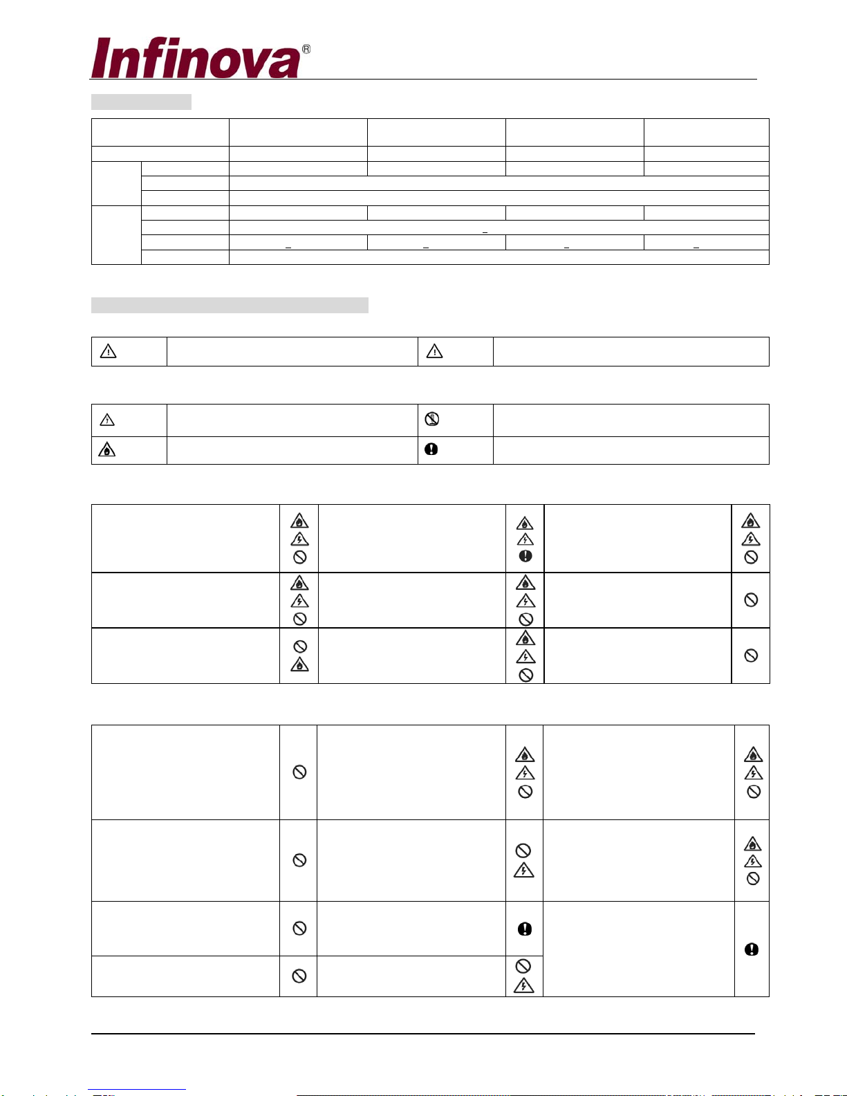
INFINOVAPRODUCT SAFETY PRECAUTIONS
These precautionary statements are classified into two levels of danger depending on the content and grade of elements that comprise the product.
Warning! If the user does not obey these instructions and misuses
the product, serious injury or loss of life may occur. Caution! If the user does not obey these instructions and misuses the
product, serious injury and/or property damage may occur.
The following symbols are used in these precautionary statements.
Shock! This symbol warns that an electrical current is present
and electric shock may occur. Do not! This symbol means that you should not disassemble the
product.
Fire! This is a fire hazard symbol that means there is the
p
ossibility of igniting fire. Direction! This symbol means that you should pay attention to certain
handling
p
rocedure
s
.
WARNING
Don’t disassemble the unit or try to put
any foreign substance in it, especially
metal of flammable matter. Doing so
could cause electrical shock and/or fire.
Don’t scratch, open, twist or heat the
connector cable because doing so may
cause fire and/or electric shock.
Don’t attempt to use product it you
suspect something isn’t right as in seeing
smoke or detecting a strange smell. If you
use the product under these conditions
fire and/or electric shock could occur.
Please keep the unit away from water. If
water should get inside the unit, stop
using immediately, otherwise electric
shock and/or fire may occur.
If the connector cable is cracked or
damaged, please exchange. If you
continue to use the damaged cable, fire
and/or electric shock may results.
Don’t look through the lens directly at the
sun since this could cause blindness.
Don’t place the unit near extreme heat,
flame or gas since combustion may occur
resulting in fire.
Don’t try to repair the unit or any power
source since that may cause fire and/or
electric shock.
Keep the product out of the reach of
children. If the product fell on a child,
injury could occur.
CAUTION
Don’t place the product in locations with
extremely low or high temperatures. Don’t
use the product in areasthat are hotter than
60 degrees Centigrade or colder than –10
degrees Centigrade. Such extremes will
effect the quality performance of the
product and could damageit.
Don’t plug in or pull out the cable to or
form an electrical outlet with wet hands.
This may result in electric shock.
Don’t place the product near a stove or
humidifier or any place where there is
high heat or moisture. Fire and/or electric
shock may occur.
Don’t point the lens directly at the sun or
other sensor light since that could damage
the image sensor on the camera and result
in poor image quality.
When attaching the lens to the camera
body, make sure you grip it securely to
avoid the possibility of the lens falling
and becoming damage.
If you going to connect the product with
another product, please read the connection
instructions from both product manuals
carefully before attempting any connection.
Otherwise damage may result to one or
both products.
Don’t drop or hit the product forcefully.
This may cause product performance
failure.
When strong the lens, keep it out of direct
sunlight. Fire could occur as result of the
light being reflected off the lens onto a
flammable substance.
Don’t place the connector cable next to a
heater since it could melt and cause fire
and/or electric shock. Don’t place in dusty and humid place.
Fire and/or electric shock may occur.
If you going to use a lens that has a tripod
mount but are using camera body that is
heavier than the lens, please use the tripod
mount on the camera. Failure to do so
could result in severe damage to the lens.
This manual suits for next models
10
Table of contents


