Ingersoll N40 User manual

ngersoil
ROTARY MOWER
N40, N44, N46
M40, M44, M46
L40, L44, L46
K40, K44. K46
Operator's Manual 9-51563
r#tft
taa-a
lngersoll . . . the new name to say for Case garden tractors.
lngersoll Equipment Co., lnc. Winneconne, Wisconsin 54986-9576
\r/
GTtal
k
Digitally signed by GTtalk
DN: cn=GTtalk, o=Gttalk,
ou,
m, c=US
Date: 2011.08.31 18:08:22
-04'00'
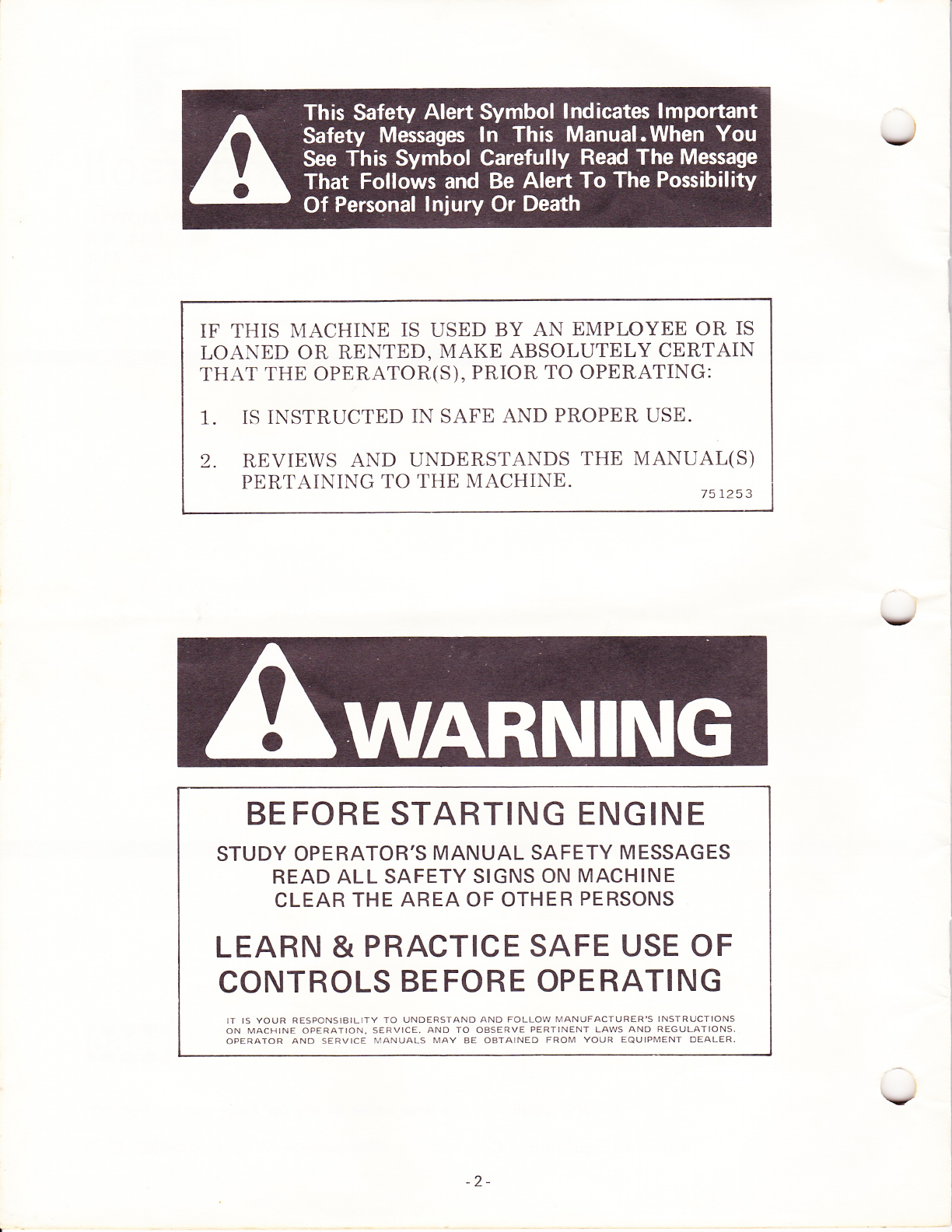
IF THIS N{ACHINE IS USED BY AN EMPLOYEE OR IS
LOANED OR RENTED, MAKE ABSOLUTELY CERTAIN
THAT THE OPERATOR(S), PRIOR TO OPERATING:
1. IS INSTRUCTED IN SAFE AND PROPER USE.
2. REVIEWS AND UNDERSTANDS THE MANUAL(S)
PERTAINING TO THE MACHINE. 751253
v
v
BEFORE STARTING ENGINE
STUDY OPERATOR'S MANUAL SAFETY MESSAGES
READ ALL SAFETY SIGNS ON MACHINE
CLEAR THE AREA OF OTHER PERSONS
LEARN & PRACTICE SAFE USE OF
CONTROLS BEFORE OPERATING
II IS YOUR RESPONSIBILITY TO UNDERSTAND AND FOLLOW MANUFACTURER'S INSTRUCTIONS
ON MACHINE OPERATION. SERVICE. AND TO OBSERVE PERTINENT LAWS AND REGULATIONS.
OPERATOR AND SERVICE [lANUALS MAY BE OBTAINED FROM YOUR EQUIPMENT OEALER.
-2-
\7
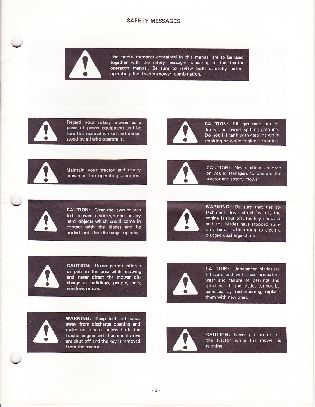
SAFETY MESSAGES
!
-3-

IMPORTANT; Always install new decals whenever
the old decals are destroyed, lost,
painted over or illegible. When indi-
vidual parts are replaced that have
decals attached, be sure to install a
new decal with the new part. Re-
placement decals are available from
your Dealer.
-4-
\z

v
v
Avoid operatinq tractor on hi!ls:des and slopes. To mini-
mize the possibility of accidenis r',trile ooerating on hills
and/or rough terrain, obey a comb;nailon of rules, prac-
tices and good common sense.
These include:
1. Reading, understanding, and obeying ail rvritten safety
messages appearing on decais on the machine and in
operator's manuals.
2. Learning from your operator's rnanual and carefully
f rom EXPERIENCE holv io operaie your tractor cor-
rectly. Know your tractor's limiiations.
3. Knowing the terrain on which you are operating your
tractor. There are terrain conditions on which yor.rr
tractor cannot be operated!
4. Learning to expect changes in operating conditions.
Adding or removing attachments or weight to your
tractor will make your tractor perform differently.
Rain, snow, loose gravel, wet grass, etc., change the
tractive conditions of the terra:n recuiring changes in
your operating technique oi- no: io ope!'ate on that
ter ra i n.
The following paragraphs rvill cover Jrese practices one at
a time. Read and study 'rhem. The examples provided are
not all inclusive but vrill g:ve yo,; a firm understanding of
the requirements for avo;d ng accidents while operating
your tractor.
Case lawn and garden tractors are designed and built to
comply with the Voluntary Standard ANSI 871.1 1980
(American National Standards lnstitute).
THE OPERATOR IS THE SOLE JUDGE AS TO THE
DEGBEE OF SLOPE ON WHICH THIS TRACTOR CAN
BE SAFELY OPERATED. IF IN DOUBT THAT THIS
TRACTOR CAN BE SAFELY OPERATED ON A PAR-
TICULAR SLOPE, DO NOT OPERATE ON THAT
SLOPE! COMMON SENSE MUST PREVAIL.
Read, Understand, @y'
Safety messages are found on the tractor and in the op-
erator's manuals. Theseq! be understood by the 114-
tor operator to be of value. Be sure that these messages
are studied before starting and/or operating the tractor by
an operator not familiar with this particular tractor.
HI LLSIDE (SLOPE) OPERATION
Learn to Opgg3.1S
Learn your tractors controls from decals on the tractor
and from instructions in the operator's manual. Practice
how to properly manipulate these controls. Practice must
be done in a flat area, clear of obstacles and bystanders.
Learn your tractors operating characteristics and limita-
tions. These include:
a, amount of engine power available
b. engine governor response
c. tractive ability
d, steering characteristics
e. braking characteristics
f. movement of travel lever
g. forward and reverse ground speeds
h. speed of attachment lift
i. and others
Attempting any operation which approaches or exceeds
the tractor's limitation is risking an accident.
Know the Terrain:
Know the terrain on which you are working. Find hidden
obstacles by walking through and inspecting the area
prior to operating your tractor on it. Mark obstacles, such
as, rocks, ruts or holes with a 6 ft. long pole and red flag
and ggy well clear of these obstacles when ope3!!S.
Operate your tractor at a ground speed slow enough to in-
sure complete control at all times.
Place the transmission in low range and regulate the travel
control lever slowly and smoothly to maintain this safe
speed.
Always drive in a forward direction when proceeding
downhill. Never drive up a hill. lf necessary, back up a
hill to the desired position. Always back up loading ramps
and tilt bed trailers. lf necessary to turn while on a hill,
always turn downward.
Your judgement, based on operating experience is the
final word in deciding if you should negotiate any given
hill or slope. lf you are in doubt about safety - g-I1\!
OFF THE SLOPE.
Under no circumstances should an inexperienced operator
attempt to use your tractor on slopes or hillsides.
v
-5-
Other manuals for N40
1
This manual suits for next models
11
Other Ingersoll Lawn Mower manuals


