Isel SK11 User manual

isel Germany AG, April 2019, deutsch
© isel Germany AG, April 2019, english
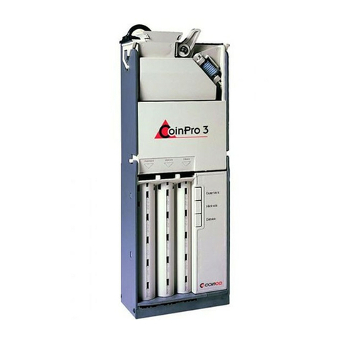
Figure 1: Turned tool changing station SK20
Turned tool changing station
SK11 and SK20
Assembly manual

Turned tool changing station SK11 and SK20
2/ 27 April 2019
About this assembly manual
Abbreviations used in this manual
MD
Machinery Directive 2006/42/EC
EMCD
EMC Directive 2004/108/EC
LVD
Low Voltage Directive 2006/95/EC
Symbols used in this manual
Various symbols are used in this manual to draw your attention to important information /
circumstances, and dangers.
Warning!
Warning of dangers which can result in harmful effects on the health, physical injury,
or death.
Warning! Life-threatening voltage
Warning of danger from electrical current. Non-observance can result in severe injury
or death.
Attention!
This symbol identifies information which must be observed in order to avoid damage
or malfunctions.
Information:
This symbol identifies important information and instructions.
Observance of safety instructions
Before you commission the SK 11 and SK20 turned tool changing stations, work
with them, or carry out expansions and/or modifications to the electrical
installation of the turned tool changing station / in the housing of the turned
tool changing station, you must carefully read the safety instructions in this
assembly manual.

Turned tool changing station SK11 and SK20
3/ 27 April 2019
The information, technical data, and dimensional specifications contained in this document
correspond to the state of the art at the time of publication. However, any print errors and mistakes
cannot be entirely ruled out. We appreciate your assistance with any recommendations for
improvement or notification of errors.
It should be stressed that the software and hardware names used in our documents are subject to
the trademark, copyright, and legal patent protection of the respective companies.
All rights reserved. No part of our documentation may be reproduced, processed using electronic
systems, duplicated, or disseminated in any other form (print or other process) without the written
consent of isel Germany AG.
isel Germany AG machines and controllers and their original accessories are CE
compliant and marked accordingly. Commissioning is not permitted for any other
machine parts and components to which the CE safety guidelines must be applied
until all corresponding requirements have been fulfilled.
isel Germany AG assumes no warranty if you carry out any modifications of the
turned tool changing station.
Manufacturer: isel Germany AG
Bürgermeister-Ebert-Strasse 40
36124 Eichenzell, Germany
Tel.: +49 6659 981-0
Fax: +49 6659 981-776
Email: [email protected]
http://www.isel.com
Revisions
Date of
change
Reason for change
Changed by
c
08/04/2019
Layout adaption, Declaration of Incorporation for (partly completed) base
machines
KJ
b
10/04/2015
Technical data
a
16/01/2015
Schematic representation
RL
28/11/2014
First print
RL

Turned tool changing station SK11 and SK20
4/ 27 April 2019
Table of contents
1General information .............................................................................................................. 5
1.1 Intended use .................................................................................................................... 5
1.2 Safety instructions ............................................................................................................ 5
2Product description ...............................................................................................................7
2.1 Types ............................................................................................................................... 7
2.1.1 Turned tool changing station SK11...........................................................................................7
2.1.2 Turned tool changing station SK20...........................................................................................7
3Connections........................................................................................................................... 8
3.1 Electrical connection......................................................................................................... 8
3.2 Pneumatic connection..................................................................................................... 10
4Assembly and commissioning.............................................................................................10
4.1 Assembly of turned tool changing station SK11, SK20 ........................................................ 10
4.1.1 SK11 assembly ......................................................................................................................10
4.1.2 SK 20 assembly......................................................................................................................11
4.2 Establishing connections................................................................................................. 11
4.3 Commissioning............................................................................................................... 16
5Technical data .....................................................................................................................23
6Maintenance and service ....................................................................................................25
7Faults .................................................................................................................................266
8Disposal .............................................................................................................................266
9 Declaration of incorporation for partly completed machinery............Fehler! Textmarke nicht
definiert.7

Turned tool changing station SK11 and SK20
5/ 27 April 2019
1General information
1.1 Intended use
The SK11 and SK20 turned tool changing stations are space-saving tool storage units with tool
slots arranged in a circle. The SK11 turned tool changing station is designed to hold and
temporarily store up to 12 milling and/or machining tools with SK11 tool holding fixtures. The SK20
changing station can accommodate up to 14 milling and/or machining tools. After actuation by the
operator, the automatic tool release takes place from a freely selected storage slot. Please refer to
the technical data for more precise features of the tools. The control of the changing station takes
place by means of the TCHUni.dll file offered by ISEL. The changing station has internal power
electronics and offers the possibility of connecting external components to an I/O interface.
General information:
Carefully read the entire assembly manual and follow the instructions. Non-observance of this
assembly manual can result in property damage, severe bodily injury, or death.
All important information about the assembly, programming, and operation of your SK11 or SK20
turned tool changing station can be found in this manual. It also provides you with important
information and notices for your safety.
1.2 Safety instructions
The SK11 and SK20 turned tool changing stations are designed
according to the state of the art and generally recognised good
engineering principles.
The equipment may only be operated in technically fault-free
condition. Faults must be rectified immediately. Children and
untrained persons may not commission the equipment.
The equipment may only be used for the intended purpose:
Changing station for milling tools with SK11 holding fixture for
SK11 turned tool changing station and SK20 holding fixture for
SK20 turned tool changing station. Control takes place by means
of the TCHUni.dll file offered by ISEL.
Do not reach into the turned tool changing station as long as the
machine is switched on and the compressed air is connected.
Prevent fires which can occur due to excessively hot tools in the
turned tool changing station.

Turned tool changing station SK11 and SK20
6/ 27 April 2019
Work may only be carried out by authorised, qualified personnel
in consideration of the regulations of the electrical and
electronics industry, as well as accident prevention regulations.
The mains plug must be pulled out before opening the housing
and performing any work on the electrical installation.
Ensure that the turned tool changing station is sufficiently
cleaned on a regular basis.
Assembly and use of the equipment must take place in
accordance with the standards of the assembly / conformity
declaration. The regulations and thresholds observed by the
manufacturer do not safeguard against unintended use of the
equipment.
The equipment may not be exposed to high air humidity and
heavy vibrations.
Store this assembly manual in a safe location and require all
users to comply with its contents!

Turned tool changing station SK11 and SK20
7/ 27 April 2019
2Product description
2.1 Types
Type
Description
Item no.
SK11 turned tool changer
11 storage slots for SK11
239100 4900
SK20 turned tool changer
14 storage slots for SK20
239100 6630
2.1.1
Turned tool changing station SK11
Powder-coated RAL3011 aluminium
housing
12 type SK11 tool slots arranged in a
circle
Monitoring of tool slot and changer
opening
Integrated power electronics
Linear movement of toolholder and
changer opening
Control by means of ISEL TCHUni.dll via
RS232 interface
Compatible with isel CNC machines
2.1.2
Turned tool changing station SK20
Powder-coated RAL3011 aluminium
housing
14 type SK20 tool slots arranged in a
circle
Monitoring of tool slot and changer
opening
Integrated power electronics
Linear movement of toolholder and
changer opening
Control by means of ISEL TCHUni.dll via
RS232 interface
Compatible with isel CNC machines

Turned tool changing station SK11 and SK20
8/ 27 April 2019
3Connections
All turned tool changing stations are optimised for operation with isel
control units. Connection cables may not be extended; otherwise the
optimal operation of the SK11 or SK20 turned tool changer can no longer
be guaranteed.
3.1 Electrical connection
*We reserve the right to technical modifications
2nd RS232 serial interface plug connection
Pin
Signal
Identification
1
n.c.
not assigned
2
RXD
RXD RS 232
3
TXD
TXD RS 232
4
n.c.
not assigned
5
Digital GND
Digital ground
6
n.c.
not assigned
7
n.c.
not assigned
8
n.c.
not assigned
9
n.c.
not assigned
If you should not have an additional RS232 serial interface on your control
computer, we recommend using a USB-RS232 adapter,
Item no.: 561050.
No.
Element
Description
2
COM
RS232 serial interface to the machine control unit
3
System IN
Voltage supply and interface to the safety circuit
4
System OUT
Connection jack for 2nd changing system
5
External I/O
Inputs and outputs for length measurement transducers,
light barriers, etc.

Turned tool changing station SK11 and SK20
9/ 27 April 2019
3. System IN plug connection
Pin
Signal
Identification
1
Stop1 IN
CH1 standstill monitor
2
Enable
Tool changer release
3
n.c.
not assigned
4
+24V
Logic +24V voltage supply
5
GND 24V
Logic GND voltage supply
6
+ Power
Motor +24V voltage supply
7
GND Power
Motor GND voltage supply
8
GND Power
Motor GND voltage supply
9
Stop2 IN
CH2 standstill monitor
10
Ready OUT
No errors of motors / power units
11
+24V
Logic +24V voltage supply
12
GND 24V
Logic GND voltage supply
13
+ Power
Motor +24V voltage supply
14
+ Power
Motor +24V voltage supply
15
GND Power
Motor GND voltage supply
4. System OUT plug connection
Pin
Signal
Identification
1
Stop1 OUT
CH1 standstill monitor, HIGH signal on standstill
2
Enable
Tool changer release
3
n.c.
not assigned
4
+24V
Logic +24V voltage supply
5
GND 24V
Logic GND voltage supply
6
+ Power
Motor +24V voltage supply
7
GND Power
Motor GND voltage supply
8
GND Power
Motor GND voltage supply
9
Stop2 OUT
CH2 standstill monitor, HIGH signal on standstill
10
Ready IN
No errors of motors / power units
11
+24V
Logic +24V voltage supply
12
GND 24V
Logic GND voltage supply
13
+ Power
Motor +24V voltage supply
14
+ Power
Motor +24V voltage supply
15
GND Power
Motor GND voltage supply

Turned tool changing station SK11 and SK20
10 / 27 April 2019
5. External I/O pin configuration
Pin
Signal
Identification
1
+24V
+24V voltage supply
2
User IN1
Input 1, freely programmable in the user software
3
User IN9
Input 9, freely programmable in the user software
4
User OUT1
Output 1, freely programmable in the user software
5
GND 24V
GND voltage supply
6
LMT IN
Length measurement transducer input, optional
7
User IN2
Input 2, freely programmable in the user software
8
User IN10
Input 10, freely programmable in the user software
9
User OUT2
Output 2, freely programmable in the user software
3.2 Pneumatic connection
No.
Description
1
Connection to compressed air supply
The turned tool changer requires an operating pressure of 8 bar and must be connected to
a maintenance unit. Required hose diameter 6mm.
4Assembly and commissioning
4.1 Assembly of turned tool changing station SK11, SK20
Ensure that you have a stable and secure foundation for the turned tool changing
station prior to commissioning. Avoid collision with other components of the
machine.
4.1.1 SK11 assembly
Figure 2: SK11 fastening
Fasten all five fastening points on the turned changer to the
mounting area of your machine with machine screws (not included
in the scope of supply) and ensure that it is flat and level.
Attention: The turned changer must be positioned in the
travel range of your CNC machine.

Turned tool changing station SK11 and SK20
11 / 27 April 2019
4.1.2 SK 20 assembly
Figure 3: SK20 fastening
4.2 Establishing connections
Attention! Switch off the mains voltage and pull out the mains plug before
connecting the tool changer! Shut off the compressed air and ensure the
absence of pressure!
Only authorised, qualified experts may carry out work on the electrical
equipment of the machine. After completion of the integration of the
turned tool changing station and prior to the initial commissioning, the
machine must undergo inspection in accordance with EN 60204-1:2006,
section 18.7. Route the cable without crossing other high-voltage cables.
Avoid sharp bends and corners when routing the cable and ensure that the
cable is not pinched and cannot be damaged as a result of movements of
the machine. Only use suitable cable guidance systems.
Fasten all six fastening points on the turned changer to the
mounting area of your machine with machine screws (not included
in the scope of supply) and ensure that it is flat and level.
Attention: The turned changer must be positioned in the
travel range of your CNC machine.

Turned tool changing station SK11 and SK20
12 / 27 April 2019
System IN interface
1)
Connect the 15 pin Sub D of the orange cable to the
System IN
slot on the turned changer.
Route the cable into the switch cabinet.
2)
Figure 4: X3 terminal strip on the last output stage
Disconnect the black AMP plug
strip, STOP1 OUT, STOP2 OUT, …
to Logic GND at terminal X3 of the
last output stage IMD 10/20/40.
3)
Plug in the black AMP plug of the
turned changer at this position.
Ensure that the colours match
(brown and green must be the
same).

Turned tool changing station SK11 and SK20
13 / 27 April 2019
4)
Figure 5: Connection to the safety circuit module
Connect the System OUT cable to
the appropriate jack on the turned
changer and route the cable to
the SKM-S1.2-E safety circuit
module in the switch cabinet.
White and black wires are already
connected at terminals X5:E1.3
and X5:E1.4 (standstill monitor of
motor modules without turned
changer). Disconnect these and
make the following connections.
white -> X5:E1.3, Stop1 IN
brown -> X5:E1.4, Stop2 IN

Turned tool changing station SK11 and SK20
14 / 27 April 2019
5)
Figure 6: Voltage supply diagram
Establishing voltage supply:
The turned tool changing station
also requires a 24V DC voltage
supply.
We recommend using a 24V
power supply unit with at least
100 watts. The voltage
connection must be made after
the main contactors
(disconnection on Emergency
STOP).
Establish the connections as
follows:
white/blue +24V
white/green and brown/green GND
The green/yellow conductor
must be connected to the
machine's protective earth
conductor.
5)
Insulate the open ends of conductors which are not needed, or completely disconnect and
remove them.
6)
Connect the COM interface to the control computer (iPC15 / iPC25).
7)
Ensure that there is an appropriate compressed air connection.
8)
Connect any accessories via the external I/O interface.
Ensure that there is a sufficient protective circuitry of the outputs with the use of
inductors, e.g. self-induction recuperation diodes.

Turned tool changing station SK11 and SK20
15 / 27 April 2019

Turned tool changing station SK11 and SK20
16 / 27 April 2019
4.3 Commissioning
Commissioning takes place with the isel ProNC software.
You should check all settings and adapt them to your tool changer.
Start ProNC,
under the menu
Settings
->
Control unit
->
Tool management
->
Changing station 1
you will find
Setup
Follow the window step-by-step (tab by tab) and adjust the necessary settings.
Here you enter your tool
changing station type.
Select the number of tool
slots.

Turned tool changing station SK11 and SK20
17 / 27 April 2019
Determine the direction
from which the tool
changer should run.
Specify the minimum
clearances before critical
movements here.
Adjust the I/Os. For this
purpose, pay attention to
the Help in ProNC.

Turned tool changing station SK11 and SK20
18 / 27 April 2019
You configure your tool
changer here. Enter the
start and/or end position of
the tool changer,
specify the interface, and
specify the individual tool
slots. Also use the detailed
Help in ProNC.
By clicking on
Parameters
you can change the speed
setting for the changing
station.
Specify the number of steps
required for a complete
rotation of the tool changer
as follows:
Gear reduction x motor step
resolution
For SK20:
5400 steps per rotation
For SK11:
800 steps per rotation
This provides the
advantage of moving the
tool changer over the
shortest path to reach the
tool.
Specify the speeds for the
tool change.

Turned tool changing station SK11 and SK20
19 / 27 April 2019
4.3.1 Teaching in the tool slots
You must define each individual tool slot in the turned tool changer. For this purpose, we recommend
arranging tool slots increasing in ascending order, beginning with 1. However, the storage slots may
also be freely assigned.
1
2
3
4
5
67
8
9
10
11
12
tool positions
12
3
4
5
6
78
9
10
11
12
13 14
tool positions
Recommended arrangement of the tool storage
slots in the SK20 turned tool changer with 14
storage slots.
You reach the drive
control of the turned
tool changer with the
Teach button.
Recommended arrangement of the tool storage
slots in the SK11 turned tool changer with 12
storage slots.

Turned tool changing station SK11 and SK20
20 / 27 April 2019
Move the turned tool changer until storage slot 1 is centred in the tool change opening.
Attention: Do not reach into the moving changing station. Danger of severe
injury.
For better control: Both tappets of the tool holder must be above the pressure plate of the ejection
cylinder.
Check the positioning of the storage slot. If everything is correct and the tool can be driven out
without danger or damage, adopt the position.
Approach the 2nd storage slot. It must also be centred in the tool change opening. Perform the same
check of the tappet as with the first storage slot.
Adopt the position and proceed with the other positions in the same manner as with storage slots 1
and 2.
When all storage slots have been taught in, please check again whether the individual positions of the
tools have actually been "ADOPTED".
For this purpose, have the turned changing station repeatedly approach the various storage slots and
check the position of the toolholder in the tool change opening.
Tappet of the tool holder
Pressure plate
Ejection cylinder
This manual suits for next models
1
Table of contents