JAMO DVR 50 User manual

1
DVR 50 - Rev. 011105-2
Jamo Service manual
DVR 50
Rev. 011105-2
DVR 50
Contents
To service personnel .......... 2 - 4 Faultfinding.................... 9 Remote control ................................ 56
Specifications........................... 5 Audio board .................10 Cabinet ...................................... 57 - 61
DVR 50 diassembly ................. 6 VFD board ....................23 Cables ............................................... 62
System overview......................7 MPEG board ................ 25 Legend and abbreviations .............. 63
Block diagram..........................8 Loader.......................... 54
HOME CINEMA SYSTEM
IMPORTANT NOTICE
This manual is intended for Jamo retailers and their appointed service representatives. Jamo assume that basic service procedures inherent to
the industry,and specifically Jamo products, are already known and understood by the users and will for that reason not be restated here.
WARNING Failure to follow appropriate service and safety procedures when servicing this product may result in personal injury,
destruction of expensive components and equipment or/and shortening the product life or/and failure of the product
to perform as specified. For these reasons Jamo strongly advice product owners that all service required should be
performed by an authorized Jamo retailer or the appointed service representative.
WARNING Static discharge can destroy expensive components, equipment or/and shorten the product life. Discharge any static
electricity accumulated in your body or materials in the vicinity of the workplace by grounding.
IMPORTANT This manual does not in its self constitute authorization, certification or establish a principle agent or partner
relationship of any form.
IMPORTANT Jamocontinuallystrivetoimprovetheirproductsandasaconsequenceofthese modificationsareinevitable.Specifications
are subject to change without notice or obligation to retrofit. Should any discrepancy appear in this manual, please
contact Jamo Call center.
IMPORTANT
Disconnect all mains power before disassembly or part replacement. Recheck all work before reapplying mains power to the unit.

2
DVR 50 - Rev. 011105-2
To service personnel
WARNING: Chemical content notice
The solder used in this product contains LEAD. In addition, other electrical/electronic and/or
plastic components may also contain traces of chemicals found to cause cancer and/or birth
defects or other reproduction harm.
Avoid prolonged, unprotected contact between the solder and your skin! Do not inhale solder
fumes or expose eyes to solder/flux vapor! If you have been in contact with solder or components
located inside the enclosure of this product, wash your hands before handling food.
Environmental information
• The system is made of recyclable materials which can be reused if disassembled by
authorized personnel.
• Please follow local regulations for the disposal of packaging materials, used batteries and
discarded units.
Important safety notice!
This product utilizes components, having special characteristics or critical for safety. These
parts are identified by mark in the schematic diagram, exploded views and spare part lists.
It is essential that these critical parts are only replaced with components specified by the
manufacturer.This is to prevent electrical shock, fire or other hazards.
Never modify the original design unless the modification is approved by the manufacturer.
General Service guidelines
When servicing, observe the original lead dress. If a short circuit is found, replace all parts which
have been overheated or damaged by the short circuit.
After servicing, see to it that all the protective devices such as insulation barriers, insulation
papers shields are properly installed.
Avoid use, of excessive force and unspecified use of glue.This may damage the product or make
future servicing impossible.
Before packing for shipment back to the costumer, make sure that the product is free of dirt and
finger marks. The product should appear as presentable as possible in order to fulfill customer
expectations.
Leakage current measurement
When service or repair has been completed,it is important to verify that all exposed conductive
surfaces are properly insulated from the circuits and mains voltage. Please make following
leakage current measurements to prevent the customer from being exposed to shock hazards.
See figure 1.
• Plug the mains cord directly into the AC outlet. Do not use an isolation transformer for
these measurements.
• Connect a 1.5K Ohm, 10 watts resistor, in parallel with a 0.15uF capacitor, between each
exposed metallic part on the product and a good earth ground such as a water pipe, as
shown in Figure 1.
• Check each exposed metallic part.
• Reverse the mains plug in the AC outlet and repeat each of the above measurements.
• Leakage current must not exceed 0,5 mA.
In case a measurement is outside the limits specified, there is a risk of shock hazard, and the
product should be repaired and rechecked before it is returned to the customer.
These leakage current measurements are according to IEC 60065 and UL 6500.
figure 1.

3
DVR 50 - Rev. 011105-2
To service personnel
Prevention of Electro Static Discharge (ESD)
Some semiconductor (solid state) devices can be damaged by static electricity. Such
components commonly are called Electrostatically Sensitive (ES) Devices. Examples
of typical ES devices are integrated circuits and some field-effect transistors and
semiconductor components. The following guidelines and techniques should be used
to help reduce the incidences of component damage caused by electro static discharge
(ESD).
• Immediately before handling any semiconductor component or semiconductor-
equipped module, discharge any ESD in your body by touching a known earth
ground. Do not remove a replacement ES device from its protective package until
immediately before you are ready to install it.
• Use a discharging ESD wrist strap during any work on the product. And use a
conductive table top or table mat. (This equipment is commercially available at a
relative low cost)
Caution! Remove the wrist strap for potential shock reasons prior to applying
power to the device under test.
• Install conductive flooring or floor mats under the workplace. And use heel straps
or conductive shoes.
• After removing an electronic assembly equipped with ES devices, place the
assembly on a conductive surface, to prevent ESD buildup or exposure of the
assembly.
• Use only a grounded soldering iron to solder or unsolder any semiconductor and
make sure that all instruments used are grounded properly.
• Use only an anti-static solder removal device. Some solder removal devices not
classified as “anti-static (ESD protected)” can generate electrical charge sufficient
to damage ES devices.
• Do not use Freon-propelled chemicals. These can generate electrical charges
sufficient to damage ES devices.
• Immediately before removing the protective material, touch the protective
material to the chassis or known earth ground of which the device will be
installed.
Caution! Be sure no power is applied to the chassis or circuit,and observe all other
safety precautions.
• Minimize bodily motions when handling unpackaged replacement ES devices.
(Otherwise harmless motion such as the brushing together of your clothes fabric
or the lifting of your foot from a carpeted floor can generate static electricity (ESD)
sufficient to damage the product).
Cleaning the product
The outside of the product may be cleaned using a damp cloth with mild detergent.
Never use abrasives or solvents like Methanol as these may damage the product.
Excessive use of water may damage the cabinet, speaker units or cause electrical shock
or short circuit.

4
DVR 50 - Rev. 011105-2
To service personnel
Preparing Jamo products for shipment
If possible, use the original packing material for any shipping. Otherwise, repack the product
using:
• A reinforced cardboard box, strong enough to carry the weight of the product.
• At least 6 cm / 2.36 inches of shock-absorbing material around the product.
• Nonabrasive dust-free material for the other parts.
• Nonabrasive wrapping for the product. (Dust and dirt cover)
• Repack the product in a manner to ensure that it cannot shift in the box during transport.
Never ship products, like speakers and subwoofers, with spikes mounded. Spikes can penetrate
the cardboard and other packing material causing serious damage.
Never pack accessories, mains cord etc. in a way that it could damage the product.
The Jamo warranty does not cover damage during shipment.The product warranty is described
in the user’s manual and on the Jamo homepage.
Receiving products
When products are received, the following procedure should be followed:
1. Inspect the outer box for damage.
2. Carefully unpack all items from the box and check for damage.
3. Check that nothing is missing according to the delivery note.
4. If you note any physical damage not stated in the fault description or missing items,
contact the sender immediately and clarify the matter.
Damage during transport is not covered by the Jamo warranty.
How to order spare parts
When ordering spare parts, we would like you to state both the Part description and Item no.
This is to avoid times consuming misunderstandings and extra shipments.
DVR 50 Serial No.:
On all DVR 50 units you will find a Serial number on the rear panel. Fig. 44-0401/8
The number is made up of tree sections. The fist section is the factory code (two digits). The
next section is the revision number (two digits). The rest of the serial number is a running serial
number starting with 3001001100.
DVR 50 models:
Manual revision No.
On the front page, in bottom right hand corner, you will find the manual revision number. The
number is basically the release date followed by a product status number. (day month year -
status No.)
The following list shows the products status No.:
• 1 is for products still in production.
• 2 is for discontinued products for which spare parts are still available.
• 3 is for discontinued products for which spare parts are no longer available.
Please note! The latest service manuals are available for download on the Jamo homepage.
Item No. Rear label Tuner model Region code Power cable Video cable TV System Countries
83990 DVR 50 - US KST-MV011MA0-B0 1 US S-video NTSC US, Canada
83991 DVR 50 - EUR KST-MV114MA1-B0 2 EU Scart PAL Europe,South Africa,Israel
83992 DVR 50 - UK KST-MV114MA1-B0 2 UK Scart PAL UK, Ireland
83993 DVR 50 - AUS KST-MV011MA0-B0 4 AUS S-video PAL Australia, New Zealand
83994 DVR 50 - LA KST-MV011MA0-B0 4 US S-video NTSC Argentina, Brazil, Mexico
83995 DVR 50 - CHN KST-MV011MA0-B0 6 EU S-video PAL China
83996 DVR 50 - TW KST-MV011MA0-B0 3 US S-video NTSC Taiwan
83997 DVR 50 - ASIA KST-MV011MA0-B0 3 EU S-video PAL Korea, Singapore
83998 DVR 50 - RUS KST-MV114MA1-B0 5 EU S-video PAL Russia
83999 DVR 50 - CHILE KST-MV011MA0-B0 4 EU S-video PAL Chile
XX

5
DVR 50 - Rev. 011105-2
Specifications
System .....................................................................................................................................................................DVD-Receiver
Weight (kg/lb) .....................................................................................................................................................................4,4/9,7
Dimensions (HxWxD/mm/in) .........................................................................................70x430x295/2,76x16,93x11,61
PowerConsumption ................................................................................................................................................. Max 120W
RatedOutput6Ohm1Khz10 ......................................................................................................................... 2 x 50/50/2 x 50
RatedOutput6Ohm1Khz1 ........................................................................................................................... 2 x 35/35/2 x 35
TuningRange ....................................................................................................................87,5 - 108.0Mhz / 522 - 1611 kHz
RadioSNRatio .....................................................................................................................................................................> 70dB
DiscFormats .....................................................CD/CD-R/CD-RW/DVD-Video/DVR-R/DVD-RW/DVD+R/DVD+RW/
VideoInputs ................................................................................................................................................................................ No
ProgressiveScan .................................................................................................................................................. Yes, PAL/NTSC
VideoOutputs .......................................................................................... Composite, S-Video, RGB(Scart), Component
PowerConsumption ................................................................................................................................................. Max 120W
AudioOutputs................................................................................................................................1x Analog/ 1x Optical Dig.

6
DVR 50 - Rev. 011105-2
DVR 50 diassembly

7
DVR 50 - Rev. 011105-2
DVR 50 System overview
1 DVD Loader
2 Tuner DVD receiver module EU/US
3 PSU assy Audio DVR 50
4 Audio board
5 VFD board
6 MPEG board
51 3
6
2
4
Top view
Rear view
Zoom for more information
* For board replacement remove following screws
12
3
4
5 7
6
8 9 10
11 12 13 14
15 16 17 18 19
1. FM antenna
2. AM antenna
3. SCART connector
4. Component video output
5. Composite video output
6. S-Video output
7. Analog audio output
8. TV analog input
9. Video analog input
10. Auxiliary analog input
11. Subwoofer output
12. Optical audio input
13. Coaxial audio input
14. Optical audio output
15. Surround speaker centre out
16. Surround speaker right out
17. Surround speaker left out
18. Right speaker out
19. Left speaker out
20. AC input
20
21
22
23
24
Detailed overview of the back panel
21. Tuner
22. Audio board
23. PSU board
21. - 22. - 23. - 24. Rear Panel
For board replacement
remove following screws
High voltage
Do not touch
during operation!

8
DVR 50 - Rev. 011105-2
DVR 50 Block diagram

9
DVR 50 - Rev. 011105-2
DVR 50 Faultfinding
The following guide is base on service reports sent in by service partner’s world wide.Try the suggested corrections in
the same order as they are listed.
Before replacing modules and components always make sure that product in front of you has the latest Firmware
version.The Firmware version can be checked in the hidden menu.To access the hidden menu:
Press LOAD to open the loader tray
Press INFO followed by 2,7,6 and you have now accessed the hidden menu.
Press MENU to close the hidden menu again.
The latest Firmware (instructions included) can be downloaded from the Jamo website under download.
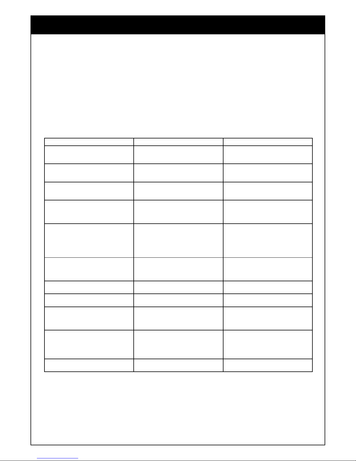
Symptom Possible cause Correction
The unit will not power up. • Bad internal cable connections.• Burned FUSE
on the PSU module.• Defective PSU module.
• Secure all cable connections.*(1)• Replace
FUSE and check unit.*(2)• Replace the PSU
module.
The unit will not BOOT. • Faulty or incorrectly burned Firmware CD.•
Bad internal cable connections.• Defective
MPEG module.• Defective LOADER module.
• Open the loader tray*(3) and try with a new
CD.• Secure all cable connections.• Replace the
MPEG module.• Replace the LOADER module.
No light in the display. • Bad internal cable connections.• Defective
VFD module.• Defective PSU module.•
Defective MPEG module.
• Secure all cable connections.• Replace the
VFD module.• Replace the PSU module.•
Replace the MPEG module.
The LOADER tray will not open. • Bad internal cable connections.• Defective
Audio module.• Defective MPEG module.•
Defective VFD module.• Defective LOADER
module.
• Secure all cable connections.• Replace the
Audio module.• Replace the MPEG module.•
Replace the VFD module.• Replace the LOADER
module.
“Noisy” LOADER • Out of balance- or off centred discs.• Loos
LOADER brackets.• Copy protection.• Poor
quality or poorly recorded media.• Defective
LOADER module.
• Discard the bad discs.• Tighten the LOADER
bracket. (see instruction under LOADER
module)• Some copy protection systems will
disrupt the playing of music. Check with other
discs.• Discard the bad discs.• Replace the
LOADER module.
Audio faults.Front speakers (Left/Right)Center
speaker.SUR speakers (Left/Right)
• Copy protection.• Bad internal cable
connections.• Defective Audio module.•
Defective PSU module.
• Some copy protection systems will disrupt
the playing of music. Check with other discs.•
Secure all cable connections.• Replace the
Audio module.• Replace the PSU module.
Audio faults.No Radio.No TV/Video/Aux.No I/O
digital/optical
• Bad internal cable connections.• Defective
Audio module.• Defective MPEG module.
• Secure all cable connections.• Replace the
Audio module.• Replace the MPEG module.
Faults on TV signals or the 12V controls.
(Missing voltage)
• Bad internal cable connections.• Defective
MPEG module.
• Secure all cable connections.• Replace the
MPEG module.
The DVR 50 unit does not respond to
commands from the remote control.
• No batteries are inserted in the remote
control.• The batteries are worn out.• Bad
internal cable connections.• Defective VFD
module.• Defective MPEG module.
• Insert new batteries.(2 x “AAA”R6P)• Replace
with new batteries.(2 x“AAA”R6P)• Secure all
cable connections.• Replace the VFD module.•
Replace the MPEG module.
The DVR 50 does not respond to any
commands.
• Power supply fluctuations or other
abnormalities such as static electricity may
interrupt correct operation.• The DVR 50
operation may have been interrupted by a non
standard disc.
• In order to completely reset the DVR 50,
unplug the power cable from the AC outlet.
Wait at least 30 seconds to allow all capacitors
to fully discharge.(personal settings will not
be affected)
The DVR 50 does not respond to some
operating commands during playback.
• Operations may not be permitted by the disc. • Read the instructions on the disc.
*(1) Especially REV. 01 units are prone to bad internal cable connections do to cable length and ferrite blocks.
*(2) The PSU module FUSE is located under the heat sink.Warning! Do not replace the FUSE unless the mains cord has
been removed! High voltage Warning! Do not touch the heat sink during operation!
*(3) The loader module can be opened by pressing the STANDBY button simultaneously with powering up the unit.
(Reconnecting the power cable)

10
DVR 50 - Rev. 011105-2
DVR 50 Audio board
Replacing the DVR 50 Audio board
• Disconnect the power cord from the AC outlet and take all necessary ESD
precaution.
• Remove the Lid. (See instruction under Lid)
• Disconnect all cables going to and from the Audio board.
• Unscrew the 4 screws holding the Audio board. See picture 44-0400/3
• Replace the board with a new Audio board. Note 1
• Reconnect the cables. Note 2
• Test the DVR 50 unit.
Important notes!
Note 1:
If washers is present. Be careful not to loose any of the isolation washers when
removing the board. There must be two plastic washers between the Audio
board and the PSU heat sink. See picture 44-0400/2. after Rev. 4 boards dos not
have washers.
Note 2:
Early models (approximately 30 units) got a sliced up Audio - MPEG cable.Special
care should be taken when refitting it after service. The sliced cables are only
seen on board Rev. 2 boards. See picture 44-0401/4
Ref. No. Item No. Part description PCS. Remarks
174101 PCB assy Audioboard DVR-50 1Rev. ≥ 4
DVR 50 Electronic moduls
Fig. 44-0400/3
Fig. 44-0400/2
Fig. 44-0401/4

11
DVR 50 - Rev. 011105-2
Components having special characteristics or critical for safety are
identified by mark and must be replaced with components
specified by the manufacturer.
Schematic diagram is subject to change without notice.
1
2
3
4
5
A B C D E F
Schematic diagram - Audio board 1/10 11
AUX_L
AUX_R
VCR_L
VCR_R
TUN_L
TUN_R
TV_L
TV_R
AUX_L
AUX_R
VCR_L
VCR_R
TUN_L
TUN_R
TV_L
TV_R
+3.3V
GND
+3.3V
+2.5V
GND
+12V
-12V
+3.3V
A_GND
+12V
-12V
+5V
+3.3V
+2.5V
GND
+3.3V
GND
+3.3V
+5V
GND
GND
+3.3V
+3.3V
GND
+3.3V
GND
A_GND
A_GND
Page 2 Page 3
Page 5
Page 6
Page 7
Page 8
Page 9 Page 10
Page 11
Page 12
Sigma Connector
SIGMA_CON.SCH
SDA
SCL
/INT
/RESET
/SPDIF_ERR_SENSE
GND
HI_MCLK
TV_R
TV_L
TUN_R
TUN_L
VCR_R
VCR_L
AUX_R
AUX_L
COAX_SPDIF
DVD_SPDIF
OPT_SPDIF
DIT_SPDIF
LINEOUTL
LINEOUTR LFE
+3.3V
A_GND
Equalizer DSP
EQ_DSP.SCH
EQ_DATA3
EQ_DATA2
EQ_DATA1
EQ_LRCLK
EQ_SCLK
EQ_MCLK
SDA
SCL
+3.3V
GND
/RESET
AMP_MCLK
AMP_SCLK
AMP_LRCLK
AMP_DATA1
AMP_DATA2
AMP_DATA3
S/PDIF Transmitter
S/PDIF_TX.SCH
+3.3V
+5V
/RESET
GND DIT_LRCLK
DIT_DATA
DIT_SCLK
DIT_MCLK
DIT_SPDIF
/Audio
Power Supply Connector
PSU_CON.SCH
GNDR
AMP_MCLK
AMP_SCLK
AMP_LRCLK
AMP_DATA1
AMP_DATA2
AMP_DATA3
SCL
SDA
/MUTE
/ERR_RCVY
/A_RESET
LFE
VCC5V
+12VR
-12VR
Analog Output
ANA_OUT.SCH
/RESET
DAC_DATA
DAC_LRCLK
DAC_MCLK
GND
+3.3V
LINEOUTL
LINEOUTR
DAC_SCLK
/A_RESET
A_GND
DSP
DSP.SCH
EQ_MCLK
EQ_SCLK
EQ_LRCLK
EQ_DATA1
EQ_DATA2
EQ_DATA3
DAC_MCLK
DAC_LRCLK
DAC_DATA
DIT_MCLK
DIT_SCLK
DIT_LRCLK
DIT_DATA
DIR_MCLK
DIR_SCLK
DIR_LRCLK
DIR_DATA
CLK_SEL
ADC_MCLK
ADC_LRCLK
ADC_SCLK
ADC_DATA
+3.3V
+2.5V
GND
SCL
SDA
/INT
/RESET
SEL_A
SEL_B
/ERR_RCVY
/MUTE
/Audio
MCLK
DAC_SCLKSPDIF_ERR
/SPDIF_ERR_SENSE
/A_RESET
Clock
CLOCK.SCH
+3.3V CLK_SEL
MCLKGND
HI_MCLK
Power Supply
PWR_SUP.SCH
+12VR
-12VR
VCC5V
GNDR
+12V
-12V
+5V
+3.3V
+2.5V
GND
Analog Input
ANA_IN.SCH
ADC_MCLK
ADC_LRCLK
ADC_SCLK
ADC_DATA
SEL_A
SEL_B
+12V
-12V
+3.3V
A_GND
AUX_L
AUX_R
VCR_L
VCR_R
TUN_L
TUN_R
TV_L
TV_R /RESET
S/PDIF Receiver
S/PDIF_RX.SCH
+3.3V
GND
OPT_SPDIF
DVD_SPDIF
COAX_SPDIF
DIR_LRCLK
DIR_SCLK
DIR_DATA
DIR_MCLK
/INT
SDA
SCL
/RESET
MCLK
SPDIF_ERR

12
DVR 50 - Rev. 011105-2
Components having special characteristics or critical for safety are
identified by mark and must be replaced with components
specified by the manufacturer.
Schematic diagram is subject to change without notice.
1
2
3
4
5
A B C D E F
Schematic diagram - Audio board 2/10 12
+3.3VD +3.3VA
+3.3VD +3.3VA
+3.3VD
+3.3VD
SEL_A
SEL_B
ADC_DATA
ADC_LRCLK
ADC_SCLK
ADC_MCLK
+12V
-12V
A_GND
AUX_R
VCR_L
VCR_R
TUN_L
TUN_R
TV_L
TV_R
/RESET
+3.3V
AUX_L
+
C313
10uF/16V
C310
100nF
R310
150R
R320
Not Mounted
C316
100nF
R318
120R
R306
100K
L301
BEAD
R325 0R0
C312
1uF/50V
R328 0R0
+
C314
10uF/16V
R311
100K
C307
10uF/16V
R303
100K
Z301
BZX84-C4V7
R307
100K
R317
120R
C301
100nF
C306
10nF
R312
150R
C308
100nF
U301 HEF4052B
X0
12
X1
14
X2
15
X3
11
Y0
1
Y1
5
Y2
2
Y3
4
EN
6
A
10
B
9
X13
Y3
VDD
16 GND 8
VEE
7
U302
CS5333-KZ
VL 1
MCLK 2
SCLK 3
SDATA 4
VA 5
GND
6
LRCK 7
DIV 8
DIF 9
TST
10
FILT+ 11
REF_GND 12
AINR
13 AINL
14
VQ 15
RST 16
R304
100K
R326 0R0
R329 0R0
R308
100K
R316
120R
R313
47K
C302
100nF
+
C303
10uF/16V
Z302
BZX84-C4V7
R314
120R
R315
120R
C311
1uF/50V
R319
120R
R301
100K
C309
10uF/16V
R309
100K
C315
100nF
R305
100K
+
C305
10uF/16V
R321
0R0
R324 0R0
R327 0R0
R322 0R0 C304
10nF
R302
100K
R323 0R0

13
DVR 50 - Rev. 011105-2
Components having special characteristics or critical for safety are
identified by mark and must be replaced with components
specified by the manufacturer.
Schematic diagram is subject to change without notice.
1
2
3
4
5
A B C D E F
Schematic diagram - Audio board 3/10 13
+3.3VD
+3.3VD
DAC_DATA
DAC_LRCLK
DAC_MCLK
GND
LINEOUTL
LINEOUTR
+3.3V
/RESET
DAC_SCLK
/A_RESET
A_GND
Connection between analog and digital ground is done here.
R406
3K3
R408
10K
+
C407
1uF/50V
R405
560R
Q402
2N3906
R410
3K3
+
C405
10uF/16V
R409
10K
C410
100nF
Q403
2N3904
R411
10K
+
C409
1uF/50V
L402
BEAD
Q401
2N3904
R401
10K
R412
Not Mounted
+
C402
10uF/16V
Q404
2N3904
C404
1.5nF
R402
560R
U401 CS4340
RST
1
SDATA
2
SCLK/DEM
3
LRCK
4
MCLK
5
DIF1
6
DIF0
7
DEM0
8FILT+ 9
VQ 10
REF_GND 11
AOUTR 12
AGND 13
VA 14
AOUTL 15
MUTEC 16
L401
BEAD
R407
3K3
C408
100nF
R403
3K3
C406
1.5nF
R404
10K
+
C403
10uF/16V
R413
10K
C401
100nF
L403
BEAD

14
DVR 50 - Rev. 011105-2
Components having special characteristics or critical for safety are
identified by mark and must be replaced with components
specified by the manufacturer.
Schematic diagram is subject to change without notice.
1
2
3
4
5
A B C D E F
Schematic diagram - Audio board 4/10 14
+3.3VA
+3.3VD
+3.3VD
+3.3VD
+3.3VA
+3.3V
CLK_SEL
GND
MCLK
HI_MCLK
U902A 74HC74
D
2
CLK
3
Q5
Q6
S
4
R
1
C905
100nF
U901A
74HC00
3
1
2
X901
Not Mounted
R907
Not Mounted
R901
1M
C901
10pF
U901E
74HC00
14
7
R908
0R0
U901B
74HC00
6
4
5
X902
24.576 MHz
R902
220R
C902
10pF
L901
BEAD
R905
33R
U902C
74HC74
Vcc 14
Vss
7
U902B 74HC74
D
12
CLK
11
Q9
Q8
R
13
S
10
U901C
74HC00
8
9
10
R903
1M
C903
10pF
L902
BEAD
R906
51R
R904
220R
C906
1uF/50V
C904
10pF
U901D
74HC00
11
12
13
C907
100nF

15
DVR 50 - Rev. 011105-2
Components having special characteristics or critical for safety are
identified by mark and must be replaced with components
specified by the manufacturer.
Schematic diagram is subject to change without notice.
1
2
3
4
5
A B C D E F
Schematic diagram - Audio board 5/10 15
GPIO10
+2.5VD
+2.5VD
+2.5VD+2.5VD
+2.5VD
+2.5VD
GPIO10
+3.3VD
+2.5VA+2.5VD
+3.3VD
+3.3VD
+3.3VD
+2.5VA
+3.3VD
+3.3VD
+3.3VD
+3.3VD
EQ_DATA1
EQ_DATA2
EQ_DATA3
EQ_LRCLK
EQ_SCLK
EQ_MCLK
DIR_LRCLK
DIR_SCLK
DIR_DATA
ADC_LRCLK
ADC_SCLK
ADC_DATA
DIR_MCLK
DAC_DATA
DAC_LRCLK
DAC_MCLK
SCL
CLK_SEL
DIT_MCLK
DIT_SCLK
DIT_LRCLK
DIT_DATA
/Audio
MCLK
ADC_MCLK
DAC_SCLK
SPDIF_ERR
/A_RESET
/ERR_RCVY
SEL_A
/RESET
SEL_B
SDA
/INT
/MUTE
GND
+3.3V
+2.5V
/SPDIF_ERR_SENSE
Title
Size Do cument Number R ev
Date: Sheet of
DSP 3.0
Audio Processing Board
A3
511
Wednesday June 04 2003
Amplifier error signal FF
Revision history
3.0: GPIO5 used to reset amp, R528 added.
3.0: Ports DET_AUX, DET_VCR, DET_TV is removed.
3.0: R529 & R530 added.
3.0: D503 added.
3.0: R508-R511 & R527changed to 1K.
3.0: C516-C519 added.
A capacitor pair (1uF and 0.1uF) must be placed at each power pin
C509
100nF
R512
10K
C511
100nF
+
C503
1uF/50V
C502
100nF
R525
33R
U502A
74HC74
D
2
CLK
3
Q5
Q6
S
4
R
1
R501
4K7
R530
3K3
R524 33R
C519
100nF
R522
33R
L501
BEAD
R529
3K3
R527
1K
D501
BAV99
C514
220pF
R513
3K3
R528
4K7
+
C505
1uF/50V
R520
200K
C504
100nF
U502C
74HC74
Vcc 14
Vss
7
R502
4K7
Q502
2N3904
C517
100nF
U502B
74HC74
D
12
CLK
11
Q9
Q8
R
13
S
10
R521
33R
R517
10K
+
C507
1uF/50V
R508
1K
R514
3K3
R507
4K7
R515
4K7
C506
100nF
R519
10K
C510
100nF
R523
33R
R503
3K3
R518
10K
R526 4K7
D502
BAV99
U503A
74LVC157A
1A
2
1B
3
2A
5
2B
6
3A
11
3B
10
4A
14
4B
13
1Y 4
2Y 7
3Y 9
4Y 12
G
15
A/B
1
D503
BAV99
+
C508
1uF/50V
R509
1K
R510
1K
R504
3K3
+
C501
1uF/50V
R506
4K7
C516
100nF U503B
74LVC157A
Vcc 16
Vss
8
R516
4K7
+
C512
2.2uF/50V
Q501
2N3904
C513
10nF
R505
4K7
U501
CS493264-CL
VD 1
DGND1 2
AUDATA3 3
GPIO10 4
GPIO11 5
SCDIN 6
SCL
7
GPIO7
8
GPIO6
9
GPIO5
10
GPIO4
11
VD2
12
DGND2
13
GPIO3
14
GPIO2
15
GPIO1
16
GPIO0
17
CS
18
SDA
19
INT
20
GPIO8
21
SDATAN1
22
VD3
23
DGND3
24
SCLKN1
25
LRCLKN1
26
SDATAN2
27
SCLKN2
28
LRCLKN2 29
CLKIN 30
CLKSEL 31
FILT2 32
FILT1 33
VA 34
AGND 35
RESET 36
DD 37
DC 38
AUDATA2 39
AUDATA1 40
AUDATA0 41
LRCLK 42
SCLK 43
MCLK 44
C518
100nF
R511
1K

16
DVR 50 - Rev. 011105-2
Components having special characteristics or critical for safety are
identified by mark and must be replaced with components
specified by the manufacturer.
Schematic diagram is subject to change without notice.
1
2
3
4
5
A B C D E F
Schematic diagram - Audio board 6/10 16
AVSS1
+3.3VA1
+3.3VD
AVSS2
+3.3VA2
+3.3VD
+3.3VD
+3.3VA2
AVSS1 AVSS2
+3.3VA1+3.3VD
EQ_DATA3
EQ_DATA2
EQ_DATA1
EQ_LRCLK
EQ_SCLK
EQ_MCLK
SCL
/RESET
AMP_MCLK
AMP_SCLK
AMP_LRCLK
AMP_DATA1
AMP_DATA2
AMP_DATA3
SDA
+3.3V
GND
TAS3103
TAS3103
C702
100nF
R706 0R0
L705
BEAD
R702 0R0
C709
10nF
L701
BEAD
U701
Not Mounted
SCLKIN
1
PWRDN
2
REG_EN
3
XTALI 4
XTALO 5
AVDD_CAP 6
A_VDSS 7
AVSS 8
MCLKI
9
TEST
10
MICROCLK_DIV
11
I2C_SDA
12
I2C_SCL
13
SDIN1
14
SDIN2
15
SDIN3
16
SDIN4
17
GPIO0
18
GPIO1
19
GPIO2
20
GPIO3
21
PLL0
22
PLL1
23
CS0
24
CS1
25
RST
26
I2CM_S
27
DVSS 28
DVDD_CAP 29
SDOUT1 30
VDSS 31
SDOUT2 32
SDOUT3 33
MCLKO 34
SCLKOUT1 35
SCLKOUT2 36
ORIN
37
LRCLK
38
R707
33R
C704
100nF
C708
10nF
C712
10nF
+
C713
1uF/50V
R703 0R0
U702
Not Mounted
SCLKIN
1
PWRDN
2
REG_EN
3
XTALI 4
XTALO 5
AVDD_CAP 6
A_VDSS 7
AVSS 8
MCLKI
9
TEST
10
MICROCLK_DIV
11
I2C_SDA
12
I2C_SCL
13
SDIN1
14
SDIN2
15
SDIN3
16
SDIN4
17
GPIO0
18
GPIO1
19
GPIO2
20
GPIO3
21
PLL0
22
PLL1
23
CS0
24
CS1
25
RST
26
I2CM_S
27
DVSS 28
DVDD_CAP 29
SDOUT1 30
VDSS 31
SDOUT2 32
SDOUT3 33
MCLKO 34
SCLKOUT1 35
SCLKOUT2 36
ORIN
37
LRCLK
38
C705
10nF
L702
BEAD
+
C701
1uF/50V
R708
33R
L703
BEAD
C711
10nF
C707
10nF
C714
100nF
R704 0R0
+
C703
1uF/50V
L704
BEAD
C706
10nF
R705 0R0
R701 0R0
C710
10nF

17
DVR 50 - Rev. 011105-2
Components having special characteristics or critical for safety are
identified by mark and must be replaced with components
specified by the manufacturer.
Schematic diagram is subject to change without notice.
1
2
3
4
5
A B C D E F
Schematic diagram - Audio board 7/10 17
+12VR
-12VR
VCC5V
GNDR
+12V
-12V
+2.5V
+3.3V
+5V
GND
Z802
AMS117
VIN
3
VOUT
2
ADJ
1
44
+
C802
47uF/16V
R803
301R
R805
301R
+
C805
47uF/16V
R804
510R
R806
301R
+
C804
47uF/16V
R801
10R
+
C803
47uF/16V
+
C801
47uF/16V
Z801
AMS117
VIN
3
VOUT
2
ADJ
1
44
R802
10R

18
DVR 50 - Rev. 011105-2
Components having special characteristics or critical for safety are
identified by mark and must be replaced with components
specified by the manufacturer.
Schematic diagram is subject to change without notice.
1
2
3
4
5
A B C D E F
Schematic diagram - Audio board 8/10 18
AD1
AD2
AD1AD0
AD0
VL+
AD2
VL+
SCL
DIR_DATA
DIR_MCLK
/INT
SDA
/RESET
MCLK
GND
COAX_SPDIF
DVD_SPDIF
OPT_SPDIF
+3.3V
DIR_LRCLK
DIR_SCLK
SPDIF_ERR
This ground should be returned
directly to AGND of U1
I2C Adress: 0010 + AD2 + AD1 + AD0
U102B
NC7SZ125M5
5
3
L103
BEAD
R106
47K
C110
220nF
C114
10nF
R105 33R
L102
BEAD
C104
10uF/16V
R104 33R
R102
1K
R108
Not Mounted
U101
CS8416-CS
RXP3
1
RXP2
2
RXP1
3
RXP0
4
RXN
5
VA+
6
AGND
7
FILT
8
RST
9
RXP4
10
RXP5
11
RXP6
12
RXP7
13
AD0
14 AD1 15
SCL 16
SDA 17
AD2 18
GPO1 19
GPO0 20
VL+ 21
DGND 22
VD+ 23
RMCK 24
OMCK 25
SDOUT 26
OSCLK 27
OLRCK 28
C113
10nF
C106
1nF
C102
100nF
R110 4K7
C107
100nF
R109 Not Mounted
C111
10nF
C115
10uF/16V C103
1nF
C105
100nF
R101
75R
R103
47K
C116
100nF
R107 Not Mounted
U102A
NC7SZ125M5
42
1
C109
10nF
L101
BEAD
C108
1nF
C112
10nF
C101
10uF/16V

19
DVR 50 - Rev. 011105-2
Components having special characteristics or critical for safety are
identified by mark and must be replaced with components
specified by the manufacturer.
Schematic diagram is subject to change without notice.
1
2
3
4
5
A B C D E F
Schematic diagram - Audio board 9/10 19
VL+
VL+
DIT_SPDIF
+3.3V
+5V
/RESET
DIT_LRCLK
DIT_SCLK
DIT_DATA
DIT_MCLK
GND
/Audio
Orig BitU BitV BitC Bit
C201
10uF/16V
R207
Not Mounted
R204
0R0
C206
1nF
C204
10uF/16V
R208
0R0
R203
Not Mounted
C202
100nF
L201
BEAD
U201 CS8405-CS
COPY/C
1
VL2+
2
EMPH
3
SFMT0
4
SFMT1
5
VD+
6
DGND
7
DGND
8
RST
9
ILRCK
12
ISCLK
13
SDIN
14 TCBL 15
AUDIO 19
VL3 20
OMCK 21
DGND 22
VL+ 23
H/S 24
APMS
10
TCBLD
11
CEN 16
V17
U18
TXN 25
TXP 26
VL4 27
ORIG 28
R205
Not Mounted
R202
Not Mounted
C203
1nF
L202
BEAD
R206
0R0
R201
0R0
C205
100nF
R209
Not Mounted

20
DVR 50 - Rev. 011105-2
Components having special characteristics or critical for safety are
identified by mark and must be replaced with components
specified by the manufacturer.
Schematic diagram is subject to change without notice.
1
2
3
4
5
A B C D E F
Schematic diagram - Audio board 10/10 20
+3.3VD
+3.3VD
+3.3VD
+3.3VD
+3.3VD
+3.3VD
SDA
/INT
GND
DIT_SPDIF
LINEOUTL
LINEOUTR
TV_L
TV_R
VCR_L
VCR_R
AUX_L
AUX_R
COAX_SPDIF
OPT_SPDIF
LFE
SCL
/RESET
+3.3V
/SPDIF_ERR_SENSE
TUN_L
HI_MCLK
DVD_SPDIF
TUN_R
A_GND
Audio Signal Connector
Digital ground
Analog ground
L026
L039
L021
L034
L023
C005
100pF
C004
100pF
C002
100pF
L041L040
U001G
74HC14
13 12
L027
L037
L020
L032
L017
J002
1224SM-24-40
1
2
3
4
5
6
7
8
9
10
11
12
13
14
15
16
17
18
19
20
21
22
23
24
L028
L019
L030
C006
100nF
U001D
74HC14
89
D001
BAV99
L035
D003
BAV99
U001E
74HC14
14
7
L038
U001A
74HC14
2 1
L018
U001C
74HC14
65
L033
C001
100pF
D002
BAV99
C007
100pF
L024
J001
1224SM-24-40
1
2
3
4
5
6
7
8
9
10
11
12
13
14
15
16
17
18
19
20
21
22
23
24
L036
C515
100nF
L022
U001B
74HC14
4 3
L025
L029
L031
C003
100pF
U001F
74HC14
11 10
D004
BAV99
Other manuals for DVR 50
2
Table of contents
Other JAMO Home Theater System manuals