Johnson P4HUE30N13006 User manual

CONTENTS
GENERAL INFORMATION . . . . . . . . . . . . . . . . . . . . . . . . . . . . .3
UNIT INSTALLATION. . . . . . . . . . . . . . . . . . . . . . . . . . . . . . . . . .4
VENTING . . . . . . . . . . . . . . . . . . . . . . . . . . . . . . . . . . . . . . . . . . .7
DUCTWORK . . . . . . . . . . . . . . . . . . . . . . . . . . . . . . . . . . . . . . . .8
UPFLOW APPLICATIONS . . . . . . . . . . . . . . . . . . . . . . . . . . . . .8
HORIZONTAL APPLICATION . . . . . . . . . . . . . . . . . . . . . . . . . .9
GAS PIPING . . . . . . . . . . . . . . . . . . . . . . . . . . . . . . . . . . . . . . .10
ELECTRICAL POWER CONNECTION . . . . . . . . . . . . . . . . . . .11
ELECTRICAL CONTROL CONNECTIONS . . . . . . . . . . . . . . .12
SAFETY CONTROLS . . . . . . . . . . . . . . . . . . . . . . . . . . . . . . . .13
TSTART-UP AND ADJUSTMENTS . . . . . . . . . . . . . . . . . . . . .14
ACCESSORY CONNECTIONS . . . . . . . . . . . . . . . . . . . . . . . . .16
OPERATION AND MAINTENANCE . . . . . . . . . . . . . . . . . . . . .18
TROUBLESHOOTING . . . . . . . . . . . . . . . . . . . . . . . . . . . . . . . .20
HORIZONTAL (WITHOUT FILTER) . . . . . . . . . . . . . . . . . . . . .22
FILTER PERFORMANCE-PRESSURE DROP
INCHES W.C. . . . . . . . . . . . . . . . . . . . . . . . . . . . . . . . . . . . . . . .23
WIRING DIAGRAM . . . . . . . . . . . . . . . . . . . . . . . . . . . . . . . . . .24
INSTALLATION
INSTRUCTIONS
CAUTION: READ ALL SAFETY GUIDES BEFORE YOU
START TO INSTALL YOUR FURNACE.
SAVE THIS MANUAL
MULTI-POSITION
GAS-FIRED FURNACES
COMMERCIAL BELT DRIVE
UPFLOW / HORIZONTAL MODELS: P4HUE30N13006
130 MBH OUTPUT
035-17443-000Rev. A (800)

035-17443-000Rev. A (800)
2Unitar
y
Products Group
CONTENTS
GENERAL INFORMATION . . . . . . . . . . . . . . . . . . . . . . . . . . . . . . 3
DESCRIPTION . . . . . . . . . . . . . . . . . . . . . . . . . . . . . . . . . . . . 3
INSPECTION . . . . . . . . . . . . . . . . . . . . . . . . . . . . . . . . . . . . . 3
NOTES, CAUTIONS & WARNINGS . . . . . . . . . . . . . . . . . . . . 3
LIMITATIONS AND LOCATION . . . . . . . . . . . . . . . . . . . . . . . 3
UNIT INSTALLATION. . . . . . . . . . . . . . . . . . . . . . . . . . . . . . . . . . . 4
COMBUSTION AIR . . . . . . . . . . . . . . . . . . . . . . . . . . . . . . . . 4
Air Source from Outdoors . . . . . . . . . . . . . . . . . . . . . . . . . . . 4
Special Combustion and Ventilation Considerations . . . . . . 5
Specially Engineered Installations . . . . . . . . . . . . . . . . . . . . 5
Combustion Air Quality . . . . . . . . . . . . . . . . . . . . . . . . . . . . . 5
VENTING . . . . . . . . . . . . . . . . . . . . . . . . . . . . . . . . . . . . . . . . . . . . 7
CATEGORY 1 - VERTICAL VENTING . . . . . . . . . . . . . . . . . . 7
CATEGORY 1 - 450 F. MAX. VENT TEMP. . . . . . . . . . . . . . 7
HORIZONTAL SIDEWALL VENTING . . . . . . . . . . . . . . . . . . 7
VENT SAFETY CHECK PROCEDURE . . . . . . . . . . . . . . . . . 7
DUCTWORK . . . . . . . . . . . . . . . . . . . . . . . . . . . . . . . . . . . . . . . . . . 8
UPFLOW APPLICATIONS . . . . . . . . . . . . . . . . . . . . . . . . . . . . . . . 8
SUPPLY PLENUM CONNECTION . . . . . . . . . . . . . . . . . . . . 8
Return Duct Connection . . . . . . . . . . . . . . . . . . . . . . . . . . . . 8
FILTER INSTALLATION . . . . . . . . . . . . . . . . . . . . . . . . . . . . 8
Bottom Return . . . . . . . . . . . . . . . . . . . . . . . . . . . . . . . . . . . . 9
HORIZONTAL APPLICATION . . . . . . . . . . . . . . . . . . . . . . . . . . . . 9
SUPPLY PLENUM CONNECTION . . . . . . . . . . . . . . . . . . . . 9
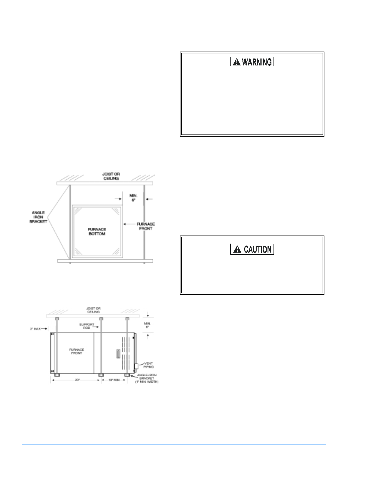
ATTIC INSTALLATION . . . . . . . . . . . . . . . . . . . . . . . . . . . . . 9
CRAWL SPACE INSTALLATION . . . . . . . . . . . . . . . . . . . . 10
GAS PIPING . . . . . . . . . . . . . . . . . . . . . . . . . . . . . . . . . . . . . . . . . 10
ELECTRICAL POWER CONNECTION . . . . . . . . . . . . . . . . . . . . 11
FURNACE CONTROL CIRCUIT . . . . . . . . . . . . . . . . . . . . . 11
BLOWER MOTOR CIRCUIT . . . . . . . . . . . . . . . . . . . . . . . . 11
ELECTRICAL CONTROL CONNECTIONS . . . . . . . . . . . . . . . . . 12
SAFETY CONTROLS . . . . . . . . . . . . . . . . . . . . . . . . . . . . . . . . . . 13
TSTART-UP AND ADJUSTMENTS . . . . . . . . . . . . . . . . . . . . . . . 14
IGNITION SYSTEM CHECKOUT / ADJUSTMENT . . . . . . . 14
CHECKING GAS INPUT . . . . . . . . . . . . . . . . . . . . . . . . . . . 14
Example - Checking Gas Input . . . . . . . . . . . . . . . . . . . . . . 14
ADJUSTMENT OF MANIFOLD GAS PRESSURE . . . . . . . . 15
ADJUSTMENT OF TEMPERATURE RISE . . . . . . . . . . . . . 16
ADJUSTMENT OF FAN-OFF CONTROL SETTINGS . . . . . 16
ACCESSORY CONNECTIONS . . . . . . . . . . . . . . . . . . . . . . . . . . 16
OPERATION AND MAINTENANCE . . . . . . . . . . . . . . . . . . . . . . 18
SEQUENCE OF OPERATION . . . . . . . . . . . . . . . . . . . . . . . 18
CONTINUOUS BLOWER . . . . . . . . . . . . . . . . . . . . . . . . . . . 18
INTERMITTENT BLOWER - COOLING . . . . . . . . . . . . . . . . 18
HEATING CYCLE . . . . . . . . . . . . . . . . . . . . . . . . . . . . . . . . . 18
HOT SURFACE IGNITION SYSTEM . . . . . . . . . . . . . . . . . . 18
MAINTENANCE . . . . . . . . . . . . . . . . . . . . . . . . . . . . . . . . . . 18
AIR FILTERS . . . . . . . . . . . . . . . . . . . . . . . . . . . . . . . . . . . . 18
LUBRICATION . . . . . . . . . . . . . . . . . . . . . . . . . . . . . . . . . . . 19
BLOWER CARE . . . . . . . . . . . . . . . . . . . . . . . . . . . . . . . . . . 19
BURNER REMOVAL / CLEANING . . . . . . . . . . . . . . . . . . . . 19
CLEANING THE HEAT EXCHANGER . . . . . . . . . . . . . . . . . 19
Lower Heat Exchanger Access . . . . . . . . . . . . . . . . . . . . . . 19
Upper Heat Exchanger Access . . . . . . . . . . . . . . . . . . . . . . 20
TROUBLESHOOTING . . . . . . . . . . . . . . . . . . . . . . . . . . . . . . . . . 20
FURNACE CONTROL DIAGNOSTICS . . . . . . . . . . . . . . . . 20
BLOWER PERFORMANCE CFM -UPFLOW/
HORIZONTAL (WITHOUT FILTER) . . . . . . . . . . . . . . . . . . . . . . . 22
FILTER PERFORMANCE-PRESSURE DROP
INCHES W.C. . . . . . . . . . . . . . . . . . . . . . . . . . . . . . . . . . . . . . . . . 23
WIRING DIAGRAM . . . . . . . . . . . . . . . . . . . . . . . . . . . . . . . . . . . . 24
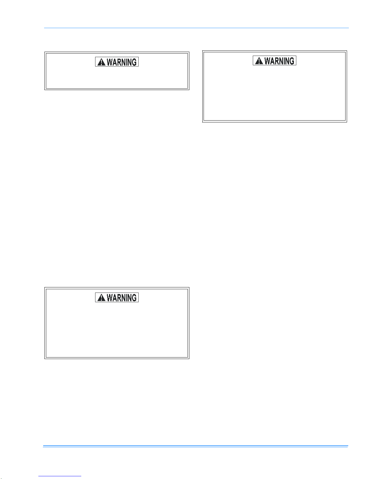
IMPROPER INSTALLATION MAY CREATE A
CONDITION WHERE THE OPERATION OF THE
PRODUCT COULD CAUSE PERSONAL INJURY
OR PROPERTY DAMAGE.
IMPROPER INSTALLATION, ADJUSTMENT,
ALTERATION, SERVICE OR MAINTENANCE
CAN CAUSE INJURY OR PROPERTY DAMAGE.
REFER TO THIS MANUAL FOR ASSISTANCE
OR ADDITIONAL INFORMATION, CONSULT A
QUALIFIED INSTALLER, SERVICE AGENCY OR
THE GAS SUPPLIER.
THIS PRODUCT MUST BE INSTALLED IN
STRICT COMPLIANCE WITH THE ENCLOSED
INSTALLATION INSTRUCTIONS AND ANY
APPLICABLE LOCAL, STATE, AND NATIONAL
CODES INCLUDING BUT NOT LIMITED TO,
BUILDING, ELECTRICAL AND MECHANICAL
CODES.
The furnace area must not be used as a broom
closet or for any other storage purposes, as a fire
hazard bay be created. Never store items such as
the following on, near or in contact with the fur-
nace.
1. Spray or aerosol cans, rags, brooms, dust mops,
vacuum cleaners or other cleaning tools.
2. Soap powders, bleaches, waxes or other cleaning
compounds; plastic items or containers; gasoline,
kerosene, cigarette lighter fluid, dry cleaning fluids
or other volatile fluid.
3. Paint thinners and other painting compounds.
4. Paper bags, boxes or other paper products
Never operate the furnace with the blower door
removed. To do so could result in serious personal
injury and/or equipment damage.

035-17443-000 Rev. A (800)
Unitar
y
Products Group 3
GENERAL INFORMATION
DESCRIPTION
This Cate
g
or
y
I furnace is desi
g
ned for installation in a resi-
dential or commercial application. A Cate
g
or
y
1 furnace has
a fan assisted combustion s
y
stem equipped with an inte
g
ral
mechanical means to draw products of combustion throu
g
h
the combustion chamber and heat exchan
g
er. It ma
y
be
installed in a basement,
g
ara
g
e, equipment room, alcove,
attic or an
y
other indoor location where all required clear-
ances to combustibles and other restrictions are met. It is
desi
g
ned for natural
g
as-fired operation, but ma
y
be con-
verted to propane (LP) usin
g
the INP0349 kit.
Hi
g
h altitude and propane (LP) chan
g
es or conversions
required in order for the appliance to satisfactoril
y
meet the
application must be made b
y
an authorized distributor: in
Canada, a certified conversion station or other qualified
a
g
enc
y
, usin
g
factor
y
specified and/or approved parts.
This furnace ma
y
be used onl
y
as a Cate
g
or
y
1 unit.
The furnace must be installed so that all electrical compo-
nents are protected from water.
INSPECTION
As soon as a unit is received, it should be inspected for possi-
ble dama
g
e durin
g
transit. If the dama
g
e is evident, the
extent of the dama
g
e should be noted on the carrier’s frei
g
ht
bill.
A separate request for inspection b
y
the carrier's a
g
ent
should be made in writin
g
. Also, before installation, the unit
should be checked for belt, screws or bolts which ma
y
have
loosened in transit.
NOTES, CAUTIONS & WARNINGS
The installer should pa
y
particular attention to the words:
NOTE, CAUTION and WARNING. NOTES are intended to
clarif
y
or make the installation easier. CAUTIONS are
g
iven
to prevent equipment dama
g
e. WARNINGS are
g
iven to alert
the installer that personal injur
y
and/or equipment or propert
y
dama
g
e ma
y
occur if installation procedures are not handled
properl
y
.
LIMITATIONS AND LOCATION
This furnace should be installed in accordance with all
national / local buildin
g
/ safet
y
codes and requirements, or in
the absence of local codes, with the National Fuel Gas Code,
ANSI Z223.1 - (latest edition) or, in Canada, CAN/CGA
B149.1 or.2 - (latest edition), and other applicable codes.
Use onl
y
the t
y
pe of
g
as approved for this furnace; refer to
the furnace ratin
g
plate.
For installations above 2,000 feet, reduce input 4% for each
1,000 feet above sea level. Canadian installations must be
derated 10% for elevations from 2,000 ft. to 4,500 ft. Use
1PS0301 kit to properl
y
derate this furnace.
The furnace shall not be connected to a chimne
y
flue servin
g
a separate appliance desi
g
ned to burn solid fuel.
Check the ratin
g
plate and power suppl
y
to be sure that elec-
trical characteristics match. All models are factor
y
wired for
208 / 230 VAC, 1 phase, 60 Hertz power suppl
y
.
A furnace installed in a residential
g
ara
g
e must be located so
that all burners and burner i
g
nition devices are located no
less than 18" above the
g
ara
g
e floor, and located or pro-
tected to prevent dama
g
e b
y
vehicles.
Each furnace in this series is a Category I furnace,
suitable for common venting with other gas-fired
appliances as allowed by the National Fuel Gas
Code, NFPA 54/ANSI Z223.1-latest edition.
This appliance is not to be used for temporary
heating of buildings or structures under construc-
tion.
Do not install this furnace in a corrosive or contam-
inated atmosphere.
Do not install this furnace in a mobile home or rec-
reational vehicle.
Furnaces shall not be installed directly on carpet-
ing, tile or other combustible material other than
wood flooring.
Continuous return air temperature must not be
below 55 °F (13 °C).
Only use natural gas in furnaces designed for nat-
ural gas. Only use propane (LP) gas for furnaces
that have been properly converted to use propane
(LP) gas. Do not use this furnace with butane.
Using wrong gas could create a hazard, resulting
in damage, injury or death.

035-17443-000Rev. A (800)
4Unitar
y
Products Group
The size of the unit should be based on an acceptable heat
loss calculation for the structure. ACCA, Manual J or other
approved methods ma
y
be used. (See Table 3 on pa
g
e 6).
The furnace should be located usin
g
these
g
uidelines:
1. Where a minimum amount of vent pipin
g
and elbows will
be required.
2. As centralized with the air distribution as possible.
3. Where adequate combustion air will be available.
4. In an area where ventilation facilities provide for safe lim-
its of ambient temperature under normal operatin
g
con-
ditions.
5. Where it will not interfere with proper air circulation in the
confined space.
6. Where the vent will not be blocked or restricted.
7. Where sufficient space is provided to allow proper ser-
vice access. Minimum recommended service clearances
are as follows:
Twent
y
-four (24) inches between the front of the furnace
and an adjacent wall or another appliance, when access
is required for servicin
g
and cleanin
g
.
Ei
g
hteen (18) inches at the side where access is
required for passa
g
e to the front for servicin
g
, inspection
or replacement of flue / vent connections.
8. Where it will not interfere with the cleanin
g
, servicin
g
or
removal of other appliances.
9. Where the followin
g
minimum clearances (in inches) to
combustibles can be maintained: Table 1 on pa
g
e5.
UNIT INSTALLATION.
COMBUSTION AIR
All installations must compl
y
with Section 5.3, Air for Com-
bustion and Ventilation of the National Fuel Gas Code, ANSI
Z223.1 or Sections 7.2, 7.3 or 7.4 of CAN/CGA B149.1 or.2
Installation Code - latest editions.
An unconfined space is not less than 50 cubic feet per 1000
Btu/hr input ratin
g
for all appliances installed in that area.
Rooms communicatin
g
directl
y
with the space containin
g
the
appliances are considered part of the unconfined space, if
openin
g
s are not furnished with doors.
A confined space is an area with less than 50 cubic feet per
1000 Btu/hr input ratin
g
for all appliances installed in that
area.
The followin
g
must be considered to obtain proper air for
combustion and ventilation in confined spaces.
Air Source from Inside the Building
Two permanent openin
g
s, one within 12 inches of the top of
the confined space and one within 12 inches of the bottom,
shall each have a free area of not less than one square inch
per 1,000 Btuh of total input ratin
g
of all appliances located in
the space. The openin
g
s shall communicate freel
y
with inte-
rior areas havin
g
adequate infiltration from the outside.
NOTE: At least 100 square inches free area shall be used for
each opening.
Air Source from Outdoors
1. Two permanent openin
g
s, one within 12 inches of the
top of the confined space and one within 12 inches of the
bottom, shall communicate directl
y
, or b
y
means of
ducts, with the outdoors or to such crawl or attic spaces
that freel
y
communicate with the outdoors.
a. Vertical Ducts - Each openin
g
must have a free
area of not less than one square inch per 4,000 Btuh
of total input of all appliances located in the space.
EXAMPLE:
b. Horizontal Ducts - Each openin
g
must have a free
area of not less than one square inch per 2,000 Btuh
of total input of all appliances located in the space.
NOTE: Ducts must have the same cross-sectional area as
the free area in the opening to which they are connected. The
minimum dimension of rectangular ducts shall be three
inches.
2. One permanent openin
g
, commencin
g
within 12 inches
of the top of the enclosure shall be permitted where the
equipment has clearances of at least 1 inch from the
sides and back and 6 inches from the front of the appli-
ance. The openin
g
shall communicate throu
g
h a vertical
or horizontal duct to the outdoors, or spaces (crawl or
attic) that freel
y
communicate with the outdoors and shall
have a minimum free area of:
a. 1 sq. in. per 3000 Btu per hr of the total input ratin
g
of all equipment located in the enclosure.
Remove blower shipping support, located under
blower assembly, only after unit has been posi-
tioned for installation or damage may occur.
Total Input of All Appliances
= Square Inches Free Area
4000

035-17443-000 Rev. A (800)
Unitar
y
Products Group 5
b. Not less than the sum of the areas of all vent con-
nectors in the confined space.
3. Louvers, Grilles and Screens
a. In calculatin
g
free area, consideration must be
g
iven
to the blockin
g
effects of louvers,
g
rilles and
screens.
If the free area of a specific louver or
g
rille is not known, refer
to Table 2 to estimate free area.
NOTE: If mechanically operated louvers are used, a means
to prevent main burner ignition and operation must be
provided should louvers close during startup or operation.
Special Combustion and Ventilation Considerations
Operation of a mechanical exhaust, such as an exhaust fan,
kitchen ventilation s
y
stem, clothes dr
y
er or fireplace ma
y
cre-
ate conditions requirin
g
special attention to avoid unsatisfac-
tor
y
operation of
g
as appliances.
Specially Engineered Installations
The above requirements shall be permitted to be waived
where special en
g
ineerin
g
, approved b
y
the authorit
y
havin
g
jurisdiction, provides an adequate suppl
y
of air for combus-
tion, ventilation and dilution of flue
g
ases.
Combustion Air Quality
The recommended source of combustion air is to use the out-
door air suppl
y
. Excessive exposure to contaminated com-
bustion air will result in safet
y
and performance related
problems. However, the use of indoor air in most applications
is acceptable, except as follows:
1. If the furnace is installed in a confined space it is recom-
mended that the necessar
y
combustion air come from
the outdoors b
y
wa
y
of attic, crawl space, air duct or
direct openin
g
.
2. If outdoor combustion air is used, there must be no expo-
sure to the installations or substances listed in #3 below.
3. The followin
g
t
y
pes of installations ma
y
require OUT-
DOOR AIR for combustion, due to chemical exposure.
a. Commercial buildin
g
s
b. Buildin
g
s with indoor pools
c. Furnaces installed in laundr
y
rooms
d. Furnaces installed in hobb
y
or craft rooms
e. Furnaces installed near chemical stora
g
e areas
f. Permanent wave solutions
g
. Chlorinated waxes and cleaners
h. Chlorine based swimmin
g
pool chemicals
i. Water softenin
g
chemicals
j. De-icin
g
salts or chemicals
k. Carbon tetrachloride
l. Halo
g
en t
y
pe refri
g
erants
m. Cleanin
g
solvents (such as perchloroeth
y
lene)
n. Printin
g
inks, paint removers, varnishes, etc.
o. H
y
drochloric acids
p. Cements and
g
lues
q. Antistatic fabric softeners for clothes dr
y
ers
r. Masonr
y
acid washin
g
chemicals
TABLE 1: UNIT CLEARANCES TO COMBUSTIBLES (ALL DIMENSIONS ARE IN INCHES)
ALL SURFACES IDENTIFIED WITH THE UNIT IN AN UPRIGHT CONFIGURATION
APPLICATION TOP FRONT REAR LEFT
SIDE RIGHT
SIDE FLUE FLOOR /
BOTTOM CLOSET ALCOVE ATTIC LINE
CONTACT
UPFLOW / HORIZONTAL MODELS - UPFLOW APPLICATION
UPFLOW 1 6 0 0 3 6 COMBUSTIBLE YES YES YES NO
UPFLOW B-VENT 1 3 0 0 0 1 COMBUSTIBLE YES YES YES NO
UPFLOW / HORIZONTAL MODELS - HORIZONTAL APPLICATION
HORIZONTAL 1 6 0 0 3 6 COMBUSTIBLE NO YES YES YES1
HORIZONTAL
B-VENT 1 3 0 0 0 1 COMBUSTIBLE NO YES YES YES1
1. Line contact only permitted between lines formed by the intersection of the rear panel and side panel (top in horizontal position) of
the furnace jacket and building joists, studs or framing.
TABLE 2: ESTIMATED FREE AREA
Wood or Metal
Louvers or Grilles Wood 20-25%
Metal 60% - 70%1
1. Do not use less than 1/4 in. mesh
Screens2
2. Free area of louvers and grilles varies widely; installer
should follow louver or grille manufacturer’s instruc-
tions.
1/4 in. mesh or larger 100%

035-17443-000Rev. A (800)
6Unitar
y
Products Group
FIGURE 1: DIMENSIONS
TABLE 3: RATINGS & PHYSICAL/ELECTRICAL DATA
MODEL INPUT
MBH
OUTPUT
MBH
AFUE1AIR TEMP
RISE °F
MAX.
OUTLET
TEMP. °F
BLOWER
TOTAL
UNIT
AMPS
M
AX
.
OVER-
CURRENT
PROTECT
M
IN
.
W
IRE
SIZE
(
AWG
)
@ 75FT.
ONE
WAY
2
OPER
WGT.
(LBS)
.
MOTOR
HP
NOMINAL
MOTOR
AMPS
@230V
SIZE
P4HUE30N13006 160 130 78 25 - 55 150 1-1/2 10 12 x 15 250
208/230 VAC (ONLY) 15 20 12
115 and 208/230 VAC (SPLIT) 6 & 11 15 12
115 VAC (ONLY)327 30 10
1. AFUE numbers are determined in accordance with DOE test procedures.
2. Wire size and overcurrent protection must comply with the National Electrical Code (ANSI / NFPA-70-latest edition)
3. Motor must be converted for 115 VAC operation.
•For altitudes above 2,000 ft., reduce capacity 4% for each 1,000 ft. above sea level. Refer to Form 650.74-N1.1V.
•Wire size based on copper conductors, 60°C, 3% voltage drop.
•See Replacement Parts list for LP gas and High Altitude conversion kits. External filter kits (bottom & side) are also available for
models above.
•Continuous return air temperatures must not be below 55°F (13°C)
Note: Vent must be increased to 5”usin
g
adaptor provided (7”tall).
All dimensions are in inches and are approximate.

035-17443-000 Rev. A (800)
Unitar
y
Products Group 7
VENTING
CATEGORY 1 - VERTICAL VENTING
Cate
g
or
y
1 ventin
g
consists of verticall
y
ventin
g
one or more
appliances in B-vent or masonr
y
chimne
y
(as allowed), usin
g
sin
g
le wall metal pipe or B-vent connectors. T
y
pe B vent s
y
s-
tem extends in a
g
eneral vertical direction and does not con-
tain offsets exceedin
g
45 de
g
rees, except that a vent s
y
stem
havin
g
not more than one 60-de
g
ree offset is permitted.
NOTE: This appliance may be common vented with another
gas appliance as allowed by the following codes and stan-
dards.
The furnace ratin
g
plate lists the maximum vent
g
as tempera-
ture. This temperature must be used to select appropriate
ventin
g
materials and clearances. A t
y
pical example is shown
below.
CATEGORY 1 - 450 F. MAX. VENT TEMP.
All installations must be vented in accordance with the
National Fuel Gas Code, NFPA 54 / ANSI Z223.1 - latest edi-
tion. For reference, the National Fuel Gas Code Handbook,
available from NFPA (item JP-54HB96) is recommended.
The appliance must also be vented in compliance with all
local utilit
y
and code requirements. In Canada, the furnace
must be vented in accordance with the National Standard of
Canada, CAN / CGA-B149.1 and.2 - latest editions.
HORIZONTAL SIDEWALL VENTING
For applications where vertical ventin
g
is not possible, the
onl
y
approved method of horizontal ventin
g
is throu
g
h the
use of an auxiliar
y
power venter. Approved power venters are
Fields Controls Model SWG-4Y or Tjernlund Model GPAK-JT.
Follow all application and installation details provided b
y
the
manufacturer of the power venter.
VENT SAFETY CHECK PROCEDURE
The followin
g
steps shall be followed with each appliance
connected to the ventin
g
s
y
stem placed in operation, while
an
y
other appliances connected to the common ventin
g
s
y
s-
tem are not in operation.
1. Seal an
y
unused openin
g
s in the common ventin
g
s
y
s-
tem.
2. Inspect ventin
g
s
y
stem for proper size and horizontal
pitch, as required in the National Fuel Gas Code ANSI
Z223.1 or the CAN / CGA B149 Installation Codes and
these instructions. Determine that there is no blocka
g
e
or restriction, leaka
g
e, corrosion or other deficiencies
which could cause an unsafe condition.
3. Insofar as is practical, close all buildin
g
doors and win-
dows and all doors between the space in which the appli-
ance(s) connected to the ventin
g
s
y
stem are located and
other spaces of the buildin
g
. Turn on clothes dr
y
ers and
an
y
other appliances not connected to the common vent-
in
g
s
y
stem.
Turn on an
y
exhaust fans, such as ran
g
e hoods and
bathroom exhausts so the
y
will operate at maximum
speed. Do not operate a summer exhaust fan. Close fire-
place dampers.
4. Follow the li
g
htin
g
instructions. Place the appliance
bein
g
operated in operation. Adjust thermostat so appli-
ance will operate continuousl
y
at full input rate.
5. Test for draft hood equipped appliance spilla
g
e at the
draft hood relief openin
g
after 5 minutes of main burner
operation. Use the flame of a match or candle.
6. After it has been determined that each appliance con-
nected to the ventin
g
s
y
stem properl
y
vents when tested
as outlined above, return doors, windows, exhaust fans,
fireplace dampers and an
y
other
g
as-burnin
g
appliance
to its previous condition of use.
7. If improper ventin
g
is observed durin
g
an
y
of the above
tests, the ventin
g
s
y
stem must be corrected.
8. An
y
corrections or resizin
g
of the common ventin
g
s
y
s-
tem must be in accordance with the National Fuel Gas
Code, ANSI Z223.1 or Section 7, Ventin
g
S
y
stems and
Air Suppl
y
for Appliances, CAN/CGA B149.1 or.2 Instal-
lation Code - latest editions. If the common vent s
y
stem
must be resized, it should be resized to approach the
minimum size as determined usin
g
the appropriate
tables in Appendix G of the above codes.
It is the responsibility of the installer to verify
proper vent system operation.
A furnace shall not be connected to a chimney flue
serving a separate appliance designed to burn
solid fuel.
This furnace requires the use of a special 4" to 5"
vent adapter. It is provided with the furnace and
must be installed.
If this furnace is replacing a common-vented fur-
nace, it may be necessary to resize the existing
vent line and chimney to prevent oversizing prob-
lems for the new combination of units. Refer to the
National Fuel Gas Code, ANSI Z223.1 or CAN/
CGA B149.1 or .2 Installation Code - latest edi-
tions.

035-17443-000Rev. A (800)
8Unitar
y
Products Group
DUCTWORK
The duct s
y
stem desi
g
n and installation must:
1. Handle an air volume appropriate for the served space
and within the operatin
g
parameters of the furnace spec-
ifications.
2. Be installed in accordance with standards of NFPA
(National Fire Protection Association) as outlined in
NFPA pamphlets 90A and 90B (- latest editions).
3. Create a closed duct s
y
stem. The suppl
y
s
y
stem must
be connected to the furnace outlet and the return duct
s
y
stem must be connected to the furnace inlet. Both sup-
pl
y
and return duct s
y
stems must terminate outside the
space containin
g
the furnace.
4. Generall
y
complete a path for heated or cooled air to cir-
culate throu
g
h the air conditionin
g
and heatin
g
equip-
ment and to and from the conditioned space.
When the furnace is used in conjunction with a coolin
g
coil,
the coil must be installed parallel with, or in the suppl
y
air
side of the furnace to avoid condensation in the primar
y
heat
exchan
g
er.
When a parallel flow arran
g
ement is used, the dampers or
other means used to control air flow must be adequate to pre-
vent chilled air from enterin
g
the furnace, and if manuall
y
operated, must be equipped with means to prevent operatin
g
of either unit unless the damper is in the full heat or cool posi-
tion.
UPFLOW APPLICATIONS
SUPPLY PLENUM CONNECTION
Attach the suppl
y
plenum to the furnace
outlet duct connection flan
g
es. This is
t
y
picall
y
throu
g
h the use of S cleat mate-
rial when a metal plenum is used. The
use of an approved flexible duct connec-
tor is recommended on all installations.
This connection should be sealed to pre-
vent air leaka
g
e.
If a matchin
g
coolin
g
coil is used, it ma
y
be placed directl
y
on the furnace outlet
and sealed to prevent leaka
g
e. Follow the
coil instructions for installin
g
the suppl
y
plenum.
On all installations without a coil, a removable access panel
is recommended in the outlet duct such that smoke or
reflected li
g
ht would be observable inside the casin
g
to indi-
cate the presence of leaks in the heat exchan
g
er. This
access cover shall be attached in such a manner as to pre-
vent leaks.
Return Duct Connection
Return air must enter the cabinet throu
g
h the bottom onl
y
, or
a bottom and one side. Sin
g
le or Dual side return onl
y
is not
allowed. Return air may not be connected into the rear
panel of the unit. See the specific t
y
pe application installa-
tion for details. Be sure to see the “Filters”section of this
instruction and side-return detail (See Fi
g
ure 2 ).
FILTER INSTALLATION
All applications require the use of a filter. All filters must be
field supplied and located outside the furnace cabinet in
either a filter rack, duct s
y
stem or filter
g
rille.
NOTE: All air velocities over 300 feet per minute, require the
use of high velocity filters.
The return air return requirements for this furnace consist of:
1. Bottom Onl
y
Return = 536 Ft./Min.
2. Bottom & Sin
g
le Side = 390 Ft./Min.
3. Bottom & Two-Sides = 300 Ft./Min.
The return duct ma
y
be attached to the furnace b
y
“S-cleat,”
bend tabs or other approved methods. Be sure to seal the
duct to the furnace to prevent air leaka
g
e.
Where the return duct s
y
stem is not complete, the return con-
nection must run full size to a location outside the utilit
y
room,
basement or space where furnace is installed. For further
details, consult Section 5.3 (Air for Combustion and Ventila-
tion) of the National Fuel Gas Code, ANSI Z223.1, or CAN /
CGA B149.1 or.2, Installation Code - latest editions.
NOTE: An external mounted (1SR0302) upflow side-return
accessory kit , which includes an aluminized mesh filter, is
available and is sized to fit the side knockouts on the cabinet.
The cooling coil must be installed in the supply air
duct downstream of the furnace.
All installations must have a filter installed.

035-17443-000 Rev. A (800)
Unitar
y
Products Group 9
.
Bottom Return
Bottom return applications normall
y
pull return air throu
g
h a
base platform or return air plenum. Be sure the return plat-
form structure is suitable to support the wei
g
ht of the furnace.
Refer to Fi
g
ure 1 on pa
g
e 6, and Table 3 on pa
g
e6 forunit
wei
g
hts and dimensions. Be sure to seal the furnace to ple-
num connection to prevent air leaka
g
e.
NOTE:A bottom filter frame accessory kit (1BR0332) is avail-
able (less filters) for this model. If the external mounted filter
rack is being used, see the instructions provided with that
accessory for installation.
Upflow attic installations must meet all minimum clearances
to combustibles and have floor support with required service
accessibilit
y
.
HORIZONTAL APPLICATION
SUPPLY PLENUM CONNECTION
The furnace ma
y
be installed horizontall
y
with the suppl
y
air-
flow toward the left or ri
g
ht b
y
la
y
in
g
the unit on the left or
ri
g
ht side panel.
After determinin
g
the best orientation, la
y
the unit on top of
the shippin
g
carton to protect the finish.
The appropriate electrical knock-outs for power wirin
g
, con-
trol wirin
g
and
g
as pipin
g
should be removed at this time.
Return air ma
y
enter the furnace throu
g
h either one side and
a bottom or throu
g
h bottom onl
y
, dependin
g
on the t
y
pe of
application. Return air may not be connected into the rear
panel of the unit. See the specific t
y
pe application installa-
tion for details. Be sure to see the Filters section of this
instruction.
ATTIC INSTALLATION
This appliance is desi
g
n certified for line contact for furnaces
installed horizontall
y
. The intersection of the furnace top and
sides form a line.
This line ma
y
be in contact with combustible material. How-
ever, refer to the “VENTING, and “CLEARANCES”sections
in this manual for additional information.
Secure a platform constructed of pl
y
wood or other buildin
g
material to the floor joists. Sheet metal, 12" in front of the fur-
nace combustion air openin
g
s is recommended. Refer to Fi
g
-
ure 3 on pa
g
e 9 for details.
NOTE: See crawl space installation for suspending the fur-
nace in attic installations.
FIGURE 2:SIDE RETURN CUTOUT MARKINGS
Do not install the unit on the rear panel.
When a furnace is installed in an attic or other
insulated space, keep all insulating materials at
least 12" away from furnace and burner combus-
tion air openings.
FIGURE 3: TYPICAL ATTIC INSTALLATION

035-17443-000Rev. A (800)
10 Unitar
y
Products Group
CRAWL SPACE INSTALLATION
The furnace can be hun
g
from floor hoists or installed on suit-
able blocks or pad. Blocks or pad installations shall provide
adequate hei
g
ht to ensure the unit will not be subject to water
dama
g
e.
When suspendin
g
the furnace from rafters or floor joists
usin
g
rod, pipe or straps, refer to Fi
g
ure 1 on pa
g
e6and
Table 3 on pa
g
e 6, for furnace wei
g
ht and dimensions to
determine suitable means of suspension.
An
g
le supports should be located as shown in Fi
g
ure 5 to
permit service of blower and burner compartments. All six
suspension points must be level to ensure proper door fit-up
and quiet furnace operation. Isolators should be used to mini-
mize noise bein
g
transferred to the structure. Furnace should
be securel
y
fastened to the bottom an
g
le iron bracket to pre-
vent movement and vibration.
GAS PIPING
NOTE:An accessible manual shutoff valve must be installed
upstream of the furnace gas controls and within 6 feet of the
furnace.
The furnace and its individual shutoff valve must be discon-
nected from the
g
as suppl
y
pipin
g
s
y
stem durin
g
an
y
pres-
sure testin
g
of that s
y
stem at test pressures in excess of 1/2
psi
g
(3.48 kPa).
The furnace must be isolated from the
g
as suppl
y
pipin
g
s
y
s-
tem b
y
closin
g
its individual external manual shutoff valve
durin
g
an
y
pressure testin
g
of the
g
as suppl
y
pipin
g
s
y
stem
at test pressures equal to or less than 1/2 psi
g
(3.48 kPa).
Gas pipin
g
ma
y
be connected from either side of the furnace.
Sizin
g
and installation of the suppl
y
g
as line should compl
y
with the local utilit
y
requirements.
The
g
as suppl
y
should be a separate line, installed in accor-
dance with the National Fuel Gas Code, ANSI Z223.1, or
CAN / CGA B149.1 or.2 Installation Codes - (latest editions).
Some utilit
y
companies, or local codes, require pipe sizes
lar
g
er than the minimum sizes listed. Use properl
y
sized
wrou
g
ht iron, approved flexible or steel pipe, to make
g
as
connections to the unit. Installation of a drop le
g
and
g
round
union is required (refer to Fi
g
ure 6 )
FIGURE 4 : TYPICAL FURNACE INSTALLATION
USING SUSPENSION MATERIALS
FIGURE 5 : TYPICAL FURNACE INSTALLATION
USING SUSPENSION MATERIALS
An overpressure protection device, such as a
pressure regulator, which conforms to the National
Fuel Gas Code, ANSI Z223.1 (US) or CAN-B149.1
or .2 (Canada) and acts to limit the downstream
pressure to value that does not exceed 0.5 PSI
(14”w.c.), must be installed in the gas piping sys-
tem upstream of the furnace. Failure to do so may
result in a fire or explosion or cause damage to the
furnace or some of its components.
Never apply a pipe wrench to the body of the com-
bination automatic gas valve. A wrench must be
placed on the projection or wrench boss of the
valve when installing piping to it.

035-17443-000 Rev. A (800)
Unitar
y
Products Group 11
.
NOTE
:
A 1/8”NPT plug is included in the inlet side of the gas
valve for measuring incoming gas pressure. Refer to Table 4
for inlet pressure information.
ELECTRICAL POWER CONNECTION
Field wirin
g
to the unit must conform to and be
g
rounded in
accordance with the provisions of the National Electrical
Code ANSI/NFPA No. 70 -latest edition, Canadian Electric
Code C22.2 Part 2 - (latest edition) and / or local codes.
Electrical wires which are field installed shall conform with the
temperature limitation for 63°F / 35°C rise wire when installed
in accordance with instructions. Specific electrical data is
g
iven on the furnace ratin
g
plate.
Provide a power suppl
y
(s) separate from all other circuits.
Install overcurrent protection and disconnect switch per
local / national electrical codes. The switch should be reason-
abl
y
close to the unit for convenience in servicin
g
. With the
disconnect switch(s) in the OFF position, check all wirin
g
a
g
ainst the unit wirin
g
label. Also, see the wirin
g
dia
g
ram in
this instruction. .
NOTE: The furnace control system depends on correct
polarity of the power supply and a proper ground connection.
Refer to the Furnace Control Diagnostics section for symp-
toms of reversed power supply polarity.
Connect the power suppl
y
as shown on the unit wirin
g
label
on the inside of the blower compartment door and as detailed
in (Refer to Fi
g
ure 7 on pa
g
e12).
FURNACE CONTROL CIRCUIT
The control circuit requires 115 volt power suppl
y
. The black
and blue leads must be connected to the hot conductor of the
power suppl
y
. Refer to Fi
g
ure 7 on pa
g
e 12.
BLOWER MOTOR CIRCUIT
The motor circuit requires 230 volt power suppl
y
as shipped.
This circuit ma
y
be chan
g
ed to 115 volts (standard 1-1/2 HP
motor onl
y
) b
y
revisin
g
the internal motor connections. Refer
to wirin
g
dia
g
ram on the motor.
All field power wirin
g
connections are shown in Fi
g
ure 7 A,
B, & C on pa
g
e 12.
Remove the 4 x 4 junction box cover plate. Route the power
wirin
g
throu
g
h the unit side panel with a conduit connector or
other proper connection. Make wirin
g
connections as shown
in Fi
g
ures 7 A, B, or C. Replace the wirin
g
box cover plate
and secure with screws.
FIGURE 6 : GAS PIPING
Compounds used on threaded joints of gas piping
must be resistant to the action of liquefied petro-
leum gases.
After all gas piping connections are completed,
leak test all joints, fittings and furnace connec-
tions with rich soap and water solution, commer-
cial available bubble type leak detection fluid, or
other approved means.
Do not use an open flame or other source of igni-
tion for leak testing.
TABLE 4: INLET GAS PRESSURE RANGE
INLET GAS PRESSURE RANGE
Natural Gas Propane (LP)
Minimum 4.5 In. W.C. 11 In. W.C.
Maximum 13.9 In W.C. 13.9 In. W.C.
Drop Leg
Use copper conductors only.

035-17443-000Rev. A (800)
12 Unitar
y
Products Group
An alternate wirin
g
method is to use a field provided 4 x 4 box
and cover on the outside of the furnace. Route the furnace
leads into the box usin
g
a protective bushin
g
where the wires
pass throu
g
h the furnace panel.
NOTE: The power connection leads and wiring box on
upflow units may be relocated to the left side of the furnace.
Remove the screws and cut wire tie holding excess wiring.
Reposition on the left side of the furnace and fasten using
holes provided. Resecure loose wires to prevent contact with
moving parts / hot surfaces and sheet metal edges.
ELECTRICAL CONTROL CONNECTIONS
Install the field-supplied thermostat. The thermostat instruc-
tions for wirin
g
are packed with the thermostat. With the ther-
mostat set in the OFF position and the main electrical source
disconnected, complete the low-volta
g
e wirin
g
from the ther-
mostat to the terminal board on the low-volta
g
e transformer.
Connect Class 2 control wirin
g
as shown in Fi
g
ures 8 and 14
“WIRING DIAGRAM”.
Appl
y
strain relief to the thermostat wires passin
g
throu
g
h the
cabinet.
NOTE: Some electronic thermostats do not have adjustable
heat anticipators. They may have other types cycle rate
adjustment. Follow the thermostat manufacturer's instruc-
tions.
The 24-Volt, 40 VA transformer is sized for the furnace com-
ponents onl
y
, and should not be connected to auxiliar
y
devices such as humidifiers, air cleaners, etc. The
transformer ma
y
provide power for an air conditionin
g
unit
contactor.
FIGURE 7A
FIGURE 7B
FIGURE 7C
7C
FIGURE 7 : ELECTRICAL WIRING
FIGURE 8 : TYPICAL HEATING AND COOLING
CONTROL CONNECTIONS
Set the heat anticipator in the room thermostat to .45
amps. Setting it lower will cause short cycles. Setting
it higher will cause the room temperature to exceed
the setpoint.
If the furnace is installed with a condensing unit
equipped with its own transformer, the condens-
ing unit control circuit must be isolated from the
furnace transformer. Refer to Figure 9 for con-
nection details.

035-17443-000 Rev. A (800)
Unitar
y
Products Group 13
To separate control circuits, use one of the follown
g
methods:
1. Install an isolation rela
y
between the thermostat and the
condensin
g
unit transformer.
2. Use a thermostat equipped with separate “R-H”and “R-
C”contacts.
NOTE: Remove the jumper between these contacts of the
thermostat, if so equipped. .
This furnace is equipped with a “Time-On”Dela
y
Rela
y
to
protect the belt-drive motor and start rela
y
if furnace oper-
ates, (1) under continuous fan mode, or (2) when installin
g
twinnin
g
kit 2TC03700124. Application of twinnin
g
kit also
requires use of “Accessor
y
Sensor Kit 2TS03700106.
SAFETY CONTROLS
Blower Door Safety Switch: This unit is equipped with an
electrical interlock switch mounted in the blower compart-
ment. This switch interrupts the 115 volt control power at the
unit when the blower door panel is removed..
Electrical suppl
y
to the unit is dependent upon the panel that
covers the blower compartment bein
g
in place and properl
y
positioned.
Rollout Switch Controls: These controls are mounted on
the burner assembl
y
. If the temperature in the burner com-
partment exceeds its set point, the i
g
niter control and the
g
as
valve are de-ener
g
ized. This is a manual reset control and
must be reset before operation can continue.
The operation of this control indicates a malfunction in the
combustion air blower or a blocked vent pipe condition.
Pressure Switch: This furnace is supplied with a differential
pressure switch which monitors the flow throu
g
h the furnace
and ventin
g
s
y
stem. This switch de-ener
g
izes the i
g
nition
control module and the
g
as valve if an
y
of the followin
g
condi-
tions are present:
1. Blocka
g
e of internal flue
g
as passa
g
ewa
y
s.
2. Blocka
g
e of vent pipin
g
.
3. Failure of combustion air blower / motor.
Limit Controls: Two hi
g
h temperature limit controls are
located on the furnace vestibule panel just to the left and ri
g
ht
of the heat exchan
g
er. This is an automatic reset control and
provides over temperature protection due to reduced airflow,
such as a dirt
y
filter or a blower motor malfunction.
Control Circuit Fuse: A 3-amp fuse is provided to protect
the 24 volt transformer from overload caused b
y
control cir-
cuit wirin
g
errors. This is an ATO-3, automotive t
y
pe fuse and
is located on the furnace control.
FIGURE 9 : TYPICAL THERMOSTAT WRIING
WITH COMMERCIAL CONDENSING
UNIT
The blower motor power supply will not be deener-
gized when the blower door is removed. Turn main
power disconnect switch to OFF to remove power
to motor.
Blower and burner must never be operated without
the blower panel in place.
Main power supply(s) to the unit must still be inter-
rupted at the main power disconnect switch(s)
before any service or repair work is to be done to
the unit. Do not rely upon the interlock switch
as a main power disconnect.

035-17443-000Rev. A (800)
14 Unitar
y
Products Group
START-UP AND ADJUSTMENTS
The initial start-up of the furnace requires the followin
g
addi-
tional procedures.
1. When the
g
as suppl
y
is initiall
y
connected to the furnace,
the
g
as pipin
g
ma
y
be full of air. In order to pur
g
e this air,
it is recommended that the
g
round joint union be loos-
ened until the odor of
g
as is detected. When
g
as is
detected, immediatel
y
reti
g
hten the union and check for
leaks. Allow five minutes for an
y
g
as to dissipate before
continuin
g
with the start-up procedure.
2. All electrical connections made in the field and in the fac-
tor
y
should be checked for proper ti
g
htness.
IGNITION SYSTEM CHECKOUT / ADJUSTMENT
1. Turn the
g
as suppl
y
ON at external manual shutoff valve
and main
g
as valve.
2. Set the thermostat above room temperature to call for
heat.
3. S
y
stem start-up will occur as follows:
a. The venter motor will start and come up to speed.
Shortl
y
after venter start-up, the hot surface i
g
niter
will
g
low for about 17 seconds.
b. After this warm-up c
y
cle, the i
g
nition module will
ener
g
ize (open) the main
g
as valve for seven sec-
onds.
NOTE: Burner ignition may not be satisfactory on first start-
up due to residual air in gas line, or until gas pressure (mani-
fold) is adjusted. The control will make three (3) attempts to
light before locking out.
4. With the furnace in operation, paint the pipe joints and
valve
g
asket lines with a rich soap and water solution.
Bubbles indicate a
g
as leak. Take appropriate steps to
stop the leaks. If the leak persists, replace the compo-
nent.
CHECKING GAS INPUT
1. Turn off all other
g
as appliances connected to
g
as meter.
2. With the furnace turned on, measure the timeneeded for
one revolution of the hand on the smallest dial on the
meter. A t
y
pical domestic
g
as meter usuall
y
has a 1/2 or
1 cubic foot test dial.
3. Usin
g
the number of seconds for each revolution and the
size of the test dial increment, find the cubic feet of
g
as
consumed per hour from Table 5.
The accurac
y
of the
g
as meter is affected b
y
both the
temperature and barometric pressure. Gas meter readin
g
s
should be accurate at 60ºF and 30.0”h.
g
. barometric pres-
sure. However, temperatures hi
g
her than 60ºF will cause the
meter to speed up resultin
g
in a hi
g
her
g
as consumption
readin
g
while lower temperatures will result in lower con-
sumption readin
g
s. For the barometric pressure, a value
g
reater than 30”h.
g
. will slow the meter while a value less
than 30”h.
g
. speeds up the meter. Dependin
g
on the condi-
tions, an error of ±5% is not uncommon.
If weather conditions si
g
nificantl
y
differ from these values at
the time when the
g
as input rate is bein
g
determined, a
g
as
meter correction factor can be easil
y
calculated to provide for
more accurate input rate adjustment. To calculate a meter
correction factor, use the followin
g
formula:
Usin
g
the information from above, calculate the
g
as input
ratin
g
b
y
multipl
y
in
g
the number of cubic feet of
g
as
consumed per hour b
y
the meter correction factor and b
y
the
Btu content (heatin
g
value) of the
g
as in
y
our particular
localit
y
. Use 1 for a meter correction factor if it was not
calculated.
NOTE:Contact your gas company for the actual heating
value of the gas in your locality as it varies widely from city to
city.
Example - Checking Gas Input
It is found b
y
measure that it takes 26 seconds for the hand
on the 1 cubic foot dial to make a revolution with onl
y
a
120,000 Btuh furnace runnin
g
. Usin
g
this information, locate
26 seconds in the first column of Table 5 on pa
g
e15.Read
across to the column headed 1 cubic foot where
y
ou will see
that 138 cubic feet of
g
as per hour are consumed b
y
the fur-
nace at that rate.
With the barometer at 28.9”and a 70ºF temperature, the
correction factor will be .945. If the local
g
as heatin
g
value is
935 BTU per cubic foot the calculations will be as follows:
(Gas Rate) x (MCF) x (Heatin
g
Value) = Hourl
y
Input Rate
(138ft3/hr)(0.945)(935 Btuh/ft3) = 121,933 Btuh
The calculated firin
g
rate of 121,933 BTU per hour is within
the
+2%
tolerance of our nominal 120,000 furnace.
If the actual input is not within
+2%
of the furnace ratin
g
, with
allowance bein
g
made for the permissible ran
g
e of the
re
g
ulator settin
g
(0.3 inches W.C.), replace the orifice spuds
with spud of the proper size.
DO NOT
omit this test! NEVER use a flame to
check for gas leaks.
(Barometric Pressure) x 520 = Meter Correction Factor
(Temperature + 460) x 30

035-17443-000 Rev. A (800)
Unitar
y
Products Group 15
ADJUSTMENT OF MANIFOLD GAS PRESSURE
1. Turn
g
as off at main
g
as valve. Remove 1/8" plu
g
/outlet
pressure tap in the main
g
as valve bod
y
and install
proper manometer tubeadapter fittin
g
. Connect line from
g
as valve tap to manometer.
2. Refer to Fi
g
ure 10 on pa
g
e 15 for location of outlet pres-
sure. Tap pressure re
g
ulator adjustment cap and screw
on main
g
as valve.
NOTE
:
The screw-off cap for the pressure regulator must be
removed entirely to gain access to the adjustment screw.
3. Turn
g
as and electrical supplies ON. Turn
g
as valve
switch to “ON”position. Start furnace and observe mani-
fold pressure on manifold.
4. If necessar
y
, adjust manifold pressure b
y
adjustin
g
g
as
valve re
g
ulator screw to a
g
ree with Table 6 values.
It ma
y
be necessar
y
to re-adjust the
g
as valve inlet pressure
(see Table 4 for values) usin
g
a similar procedure but usin
g
the inlet pressure tap on valve - adjust line re
g
ulator.
If
g
as valve re
g
ulator is turned in, or clockwise, manifold
pressure is increased. If screw is turned out, or counterclock-
wise, manifold pressure will decrease.
FIGURE 10 : GAS VALVES
TOP - WHITE-RODGERS 36F52-252
BOTTOM - HONEYWELL VR8205
TABLE 5: GAS RATE (CUBIC FEET PER HOUR)
SECONDS FOR SIZE OF TEST DIAL
ONE REVOLUTION 1/2 CUBIC FOOT 1 CUBIC FOOT
10 180 360
12 150 300
14 129 257
16 113 225
18 100 200
20 90 180
22 82 164
24 75 150
26 69 138
28 64 129
30 60 120
32 56 113
34 53 106
36 50 100
38 47 95
40 45 90
42 43 86
44 41 82
46 39 78
48 37 75
50 36 72
52 35 69
54 34 67
56 32 64
58 31 62
60 30 60
Be sure to relight any gas appliances that were
turned off at the start of this input check.
The cap must be replaced in order for the furnace
to operate properly.
TABLE 6: MANIFOLD PRESSURE
Natural Gas 3.5" W.C.
Propane (LP) 10.0" W.C.
The manifold pressure must be checked with the
screw-off cap in place on the pressure regulator.
If manifold pressure is too high, an over-fire condi-
tion exists which could cause heat exchanger fail-
ure. If the manifold pressure is too low, sooting
and eventual clogging of the heat exchanger could
occur.

035-17443-000Rev. A (800)
16 Unitar
y
Products Group
5. Once the correct
g
as pressure to the burners has been
established, turn the
g
as valve switch to OFF and turn
the electrical suppl
y
switch OFF; then, remove the pres-
sure tap at the
g
as valve and re-install the plu
g
usin
g
a
compound (on the threads) resistant to the action of LP
g
ases.
6. Turn the electrical and
g
as supplies back on, and, with
the burners in operation, check for
g
as leaka
g
e around
the plu
g
with a soap and water solution.
ADJUSTMENT OF TEMPERATURE RISE
The temperature rise, or temperature difference between the
return air and the heated air from the furnace, must be within
the ran
g
e shown on the furnace ratin
g
plate and within the
application limitations shown in Table 3. After the temperature
rise has been determined, the airflow (cfm) can be calcu-
lated. Refer to Blower Performance Matrix, Table 7 on pa
g
e
22.
After about 20 minutes of operation, determine the furnace
temperature rise. Take readin
g
s of both the return air and the
heated air in the ducts, about six feet from the furnace where
the
y
will not be affected b
y
radiant heat.
Increase the blower speed to decrease the temperature rise;
decrease the blower speed to increase the rise. Blower
speed adjustment is made as follows:
1. Remove the belt and loosen the set screw in the adjust-
able flan
g
e of the motor pulle
y
.
2. Close the pulle
y
to decrease the temperature rise; open
the pulle
y
to increase the rise.
3. Position the set screw with one of the flats on the pulle
y
hub and ti
g
hten it.
4. Ali
g
n the fixed flan
g
e of the motor pulle
y
with the blower
pulle
y
.
5. Adjust the belt tension with the motor adjustin
g
bolt until
the belt can be depressed 1" with a fin
g
er at a point half-
wa
y
between the two pulle
y
s. Loosen the (4) motor
mount bolts to permit adjustment. Reti
g
hten bolts after
adjustin
g
.
6. Repeat the pulle
y
adjustment procedure until the
desired temperature rise is obtained.
ADJUSTMENT OF FAN-OFF CONTROL SETTINGS
This furnace is equipped with a time-on / time-off heatin
g
fan
control. The fan on dela
y
is fixed at 30 seconds. the fan off
dela
y
is field adjustable from 60 to 180 seconds. The fan off
dela
y
is factor
y
set to 120 seconds.
The “fan-off”settin
g
must be lon
g
enou
g
h to adequatel
y
cool
the furnace, but not so lon
g
that cold air is blown into the
heated space. The “fan-off”timin
g
ma
y
be adjusted b
y
posi-
tionin
g
the jumper (refer to Fi
g
ure 11 ) located on the con-
trol board.
ACCESSORY CONNECTIONS
The furnace control will allow power switchin
g
control of vari-
ous accessories. Refer to Fi
g
ure 12 for connection details.
Electronic Air Cleaner Connection: Two 1/4" spade termi-
nals (EAC and EAC N) for electronic air cleaner connections
are located on the control board. The terminals provide 115
VAC (1.0 amp maximum) durin
g
circulatin
g
blower operation.
Humidifier Connection: Two 1/4" spade terminals (HUM
and HUM N) for humidifier connections are located on the
control board. The terminals provide 115 VAC (1.0 amp maxi-
mum) durin
g
heatin
g
s
y
stem operation
Twinning: When two furnaces are installed usin
g
the same
duct s
y
stem, it is ver
y
important that the two furnaces circu-
latin
g
air blowers operate simultaneousl
y
. If one blower starts
before the second blower, the duct s
y
stem will become pres-
surized with air and the second blower will be made to turn
backwards. Durin
g
heatin
g
operation, this will cause over-
heatin
g
of the second furnace, possibl
y
causin
g
an unsafe
condition and dama
g
e to the furnace. If twinnin
g
of two fur-
Be sure that the gas valve pressure regulator cap
is replaced.
Improper alignment will cause excessive noise,
belt wear and bearing failure.
FIGURE 11 : FAN-OFF TIME ADJUSTMENT

035-17443-000 Rev. A (800)
Unitar
y
Products Group 17
naces is desired, it is necessar
y
to use the accessor
y
twinin
g
kit that is desi
g
ned for use with these furnaces.
This furnace is equipped with a “Time-On”Dela
y
Rela
y
which
is required to protect the belt-drive motor/starter if operated
(1) under continuous fan mode, or (2) when installin
g
twin-
nin
g
kit 2TC03700124. Application of twinnin
g
kit also
requires use of “Accessor
y
Sensor Kit 2TS03700106.
FIGURE 12 : ACCESSORY CONNECTIONS

035-17443-000Rev. A (800)
18 Unitar
y
Products Group
OPERATION AND MAINTENANCE
SEQUENCE OF OPERATION
The followin
g
describes the sequence of operation of the fur-
nace. See “WIRING DIAGRAM”Fi
g
ure 14, for component
location. Refer to Fi
g
ure 13 for event schedule.
CONTINUOUS BLOWER
On coolin
g
/ heatin
g
thermostats with fan switch, when the
fan switch is set in the ON position, a circuit is completed
between terminals R and G of the thermostat. The blower
motor is ener
g
ized throu
g
h the contactor and runs at the
selected speed.
INTERMITTENT BLOWER - COOLING
On coolin
g
/ heatin
g
thermostats with fan switch, when the
fan switch is set in the auto position and the thermostat calls
for coolin
g
, a circuit is completed between the R, Y and G ter-
minals. The motor is ener
g
ized throu
g
h the contactor and
runs at the selected speed. The No “On-Dela
y
”“Fan-Off”set-
tin
g
is fixed at 60 seconds for SEER enhancement.
HEATING CYCLE
When the s
y
stem switch is set on HEAT, the fan is set on
AUTO, and the room thermostat calls for heat, a circuit is
completed between the terminals R and W of the thermostat.
When the proper amount of combustion air is bein
g
provided,
a pressure switch activates the i
g
nition control.
The i
g
nition control provides a 17-second warm-up period.
The
g
as valve then opens for seven seconds.
As
g
as starts to flow and i
g
nition occurs, the flame sensor
be
g
ins its sensin
g
function. If a flame is detected within seven
seconds after i
g
nition, normal furnace operation continues
until the thermostat circuit between R and W is opened. After
flamme is present for 30 seconds, the circulatin
g
blower is
ener
g
ized.
When the thermostat circuit opens, the i
g
nition control is de-
ener
g
ized. With the i
g
nition control de-ener
g
ized, the
g
as
flow stops and the burner flames are extin
g
uished. The
ventor continues to operate for 15 seconds after the
g
as flow
stops.
The blower motor continues to operate for the amount of time
set b
y
the fan-off dela
y
switches located on the control board.
The heatin
g
c
y
cle is then complete and the unit is read
y
for
the start of the next heatin
g
c
y
cle.
If the flame is not detected within the seven second sensin
g
period, the
g
as valve is de-ener
g
ized. The control is
equipped with a re-tr
y
option. This provides a 60-second wait
followin
g
an unsuccessful i
g
nition attempt (flame not
detected).
After the 60-second wait, the i
g
nition sequence is restarted
with an additional 10 seconds of i
g
niter warm-up time. If this
i
g
nition attempt is unsuccessful, one more re-tr
y
will be
made before lockout.
A momentar
y
loss of
g
as suppl
y
, flame blowout, or a shorted
or open condition in the flame probe circuit will be sensed
within 0.8 seconds.
The
g
as valve will de-ener
g
ize and the control will restart the
i
g
nition sequence immediatel
y
. Rec
y
cles will be
g
in and the
burner will operate normall
y
if the
g
as suppl
y
returns, or the
fault condition is corrected prior to the last i
g
nition attempt.
Otherwise, the control will lockout.
The control will repeat the i
g
nition sequence for a total of two
rec
y
cles if flame is lost within the first 10 seconds of
establishment.
If flame is established for more than 10 seconds after i
g
nition,
the control will clear the i
g
nition attempt (retr
y
) counter. If
flame is lost after 10 seconds, it will restart the i
g
nition
sequence. This can occur a maximum of five times.
Durin
g
burner operation, a momentar
y
loss of power of 50
millseconds or lon
g
er will drop out the main
g
as valve. When
the power is restored, the
g
as valve will remain de-ener
g
ized
and a restart of the i
g
nition sequence will be
g
in immediatel
y
.
HOT SURFACE IGNITION SYSTEM
MAINTENANCE
AIR FILTERS
The filters should be checked periodicall
y
for dirt accumula-
tion. Dirt
y
filters
g
reatl
y
restrict the flow of air and overburden
the s
y
stem.
Clean (or replace) the filters at least ever
y
three months. On
new construction, check the filters ever
y
week for the first
Do not attempt to light this furnace by hand (with a
match or any other means). There may be a
potential shock hazard from the components of the
hot surface ignition system. The furnace can only
be lit automatically by its hot surface ignition sys-
tem.

035-17443-000 Rev. A (800)
Unitar
y
Products Group 19
four weeks. Inspect the filters ever
y
three weeks after that,
especiall
y
if the s
y
stem is runnin
g
constantl
y
.
LUBRICATION
Blower and venter motors in these furnaces are permanentl
y
lubricated and do not require periodic oilin
g
.
BLOWER CARE
Even with
g
ood filters properl
y
in place, blower wheels and
motors will become dust laden after lon
g
months of opera-
tion. The entire blower assembl
y
should be inspected annu-
all
y
. If the motor and wheel are heavil
y
coated with dust, the
y
can be brushed and cleaned with a vacuum cleaner.
The procedure for removin
g
the blower assembl
y
for cleanin
g
is as follows:
1. Turn off electrical power suppl
y
to the furnace at discon-
nect switch(s). Remove access doors. Remove motor
harness usin
g
3 wires on panel.
2. Remove the screws holdin
g
the control box to the
blower. Swin
g
the control box out of the wa
y
to allow
removal of the blower.
3. Remove blower/motor assembl
y
, shippin
g
screws (2),
and deck screws; Stop and slide the blower assembl
y
out of the slots in the deck.
4. When cleanin
g
or servicin
g
the blower assembl
y
, DO
NOT remove or chan
g
e the balance clips on the blower
wheel.
5. To reassemble, reverse the procedure, restore power to
the furnace and verif
y
operation.
6. To re-assemble, reverse the procedure, restore power
and verif
y
operation.
BURNER REMOVAL / CLEANING
The main burners should be checked periodicall
y
for dirt
accumulation.
If cleanin
g
is required, follow this procedure:
1. Turn off the electrical power to the unit and turn off
g
as
suppl
y
at the shutoff valve.
2. Remove the blower and burner compartment access
doors.
3. Unplu
g
i
g
niter from the wire harness and remove the
i
g
niter / bracket assembl
y
from the burner air shield.
Handle the i
g
niter carefull
y
as it is fra
g
ile and easil
y
bro-
ken.
4. Note the location and then disconnect the senser and
rollout switch wires located on the top of the air shield
and remove the shield.
5. Remove the two screws securin
g
each burner to the
burner assembl
y
. Note the orientation of the burner
(flan
g
ed side down) before removin
g
. Burners ma
y
be
cleaned b
y
rinsin
g
in hot water or b
y
usin
g
a vacuum
cleaner.
6. To re-assemble - reverse the procedure. Restore power
and verif
y
operation.
CLEANING THE HEAT EXCHANGER
NOTE:If heat exchanger is sooted, it is recommended that
the heat exchanger be replaced due to difficulty in cleaning.
Lower Heat Exchanger Access
1. Turn off the electrical power to the unit and turn off
g
as
suppl
y
at the shutoff valve.
2. Remove the blower and burner compartment access
doors. Disconnect the
g
as suppl
y
pipin
g
at the union to
permit removal of the entire burner and
g
as control
assembl
y
from the vestibule panel. Use the wrench boss
on the
g
as valve when removin
g
or installin
g
this pipin
g
.
3. Unplu
g
the i
g
niter from the wire harness. Disconnect
senser and rollout switch wires located on top of the air
shield. Identif
y
and note the location of all leads for ease
of reinstallation. Also disconnect the wires at the side
rollout switches (upflow onl
y
) and the
g
as valve wires.
4. Remove the screws holdin
g
the burner assembl
y
to the
vestibule panel and remove this assembl
y
. Handle the
assembl
y
carefull
y
since it contains the i
g
niter which is
fra
g
ile and easil
y
broken. The lower portion of the heat
exchan
g
er will now be exposed. To clean the burner
assembl
y
, use a vacuum cleaner, or remove the burners
as outlined in burner cleanin
g
, and clean in hot water.
When replacing filters,
DO NOT
use a type with
excessively high pressure drop. Some high effi-
ciency filters available will cause the furnace to
operate improperly and could result in a safety
hazard.
This blower motor assembly weighs 90 lbs. Have
adequate support to prevent injury.

035-17443-000Rev. A (800)
20 Unitar
y
Products Group
Upper Heat Exchanger Access
1. Perform steps 1-4 above.
2. Disconnect vent pipin
g
from the vent motor assembl
y
at
the top panel on the furnace.
3. Unplu
g
the venter motor wires and
g
round wire. Remove
the pressure switch tubin
g
at the tap on the venter motor
housin
g
.
NOTE: It is recommended that replacement gaskets be
available before removing venter motor.
4. Remove six mountin
g
screws that hold the venter motor
to the restrictor plate. The surface is
g
asketed and
g
as-
ket can be reused if it is carefull
y
removed. It is neces-
sar
y
to remove this assembl
y
to
g
ain access to the
restrictor plate mountin
g
holes. The assembl
y
ma
y
be
vacuumed if cleanin
g
is necessar
y
. If an
y
vent assembl
y
parts are dama
g
ed, replace with an entire new assembl
y
(except for
g
askets).
5. Remove the perimeter screws attachin
g
the restrictor
plate assembl
y
to the vestibule panel. The surface is
also
g
asketed. The assembl
y
, includin
g
the flue baffle
plate (rear) ma
y
be vacuumed or cleaned with hot water
if necessar
y
.
6. The upper portion of the heat exchan
g
er is now accessi-
ble. With a lon
g
flexible wire brush, clean inside each
tube at both the top and bottom. The brush must pass
around the rear heat exchan
g
er tubes. Vacuum loose
scale and dirt from each tube.
7. Clean - Replace all components in reverse order. Re
g
as-
ket all surfaces which required a
g
asket. Reconnect all
wirin
g
. Reattach vent pipe and
g
as suppl
y
lines before
restorin
g
service to furnace. Restore electrical power,
check
g
as suppl
y
pipin
g
for leaks, then verif
y
furnace
operation.
TROUBLESHOOTING
The followin
g
visual checks should be made before trouble-
shootin
g
:
1. Check to see that the power to the furnace and the i
g
ni-
tion control module is ON.
2. The manual shutoff valves in the
g
as line to the furnace
must be open.
3. Make sure all wirin
g
connections are secure.
4. Review the sequence of operation.
Start the s
y
stem b
y
settin
g
the thermostat above the room
temperature. Observe the s
y
stem's response. Then use the
troubleshootin
g
section in this manual to check the s
y
stem's
operation.
FURNACE CONTROL DIAGNOSTICS
The furnace has a built-in, self dia
g
nostic capabilit
y
. If a s
y
s-
tem problem occurs, a fault code is shown b
y
a blinkin
g
LED.
It is located behind a clear view port in the blower compart-
ment door. DO NOT remove the furnace blower compartment
panel OR turn off furnace power as either action will clear the
control's memor
y
of the fault.
The control continuousl
y
monitors its own operation and the
operation of the s
y
stem. If a failure occurs, the LED will indi-
cate the failure code. If the failure is internal to the control, the
li
g
ht will sta
y
on continuousl
y
. In this case, the entire control
should be replaced as the control is not field repairable.
Flash sequence codes 1 thou
g
h 11 are as follows; LED will
turn “on”for one second and “off”for one second. This pat-
tern will be repeated the number of times equal to the code.
For example, six “on”flashes equals a number 6 fault code.
All flash code sequences are broken b
y
a 2 second “off”
period.
CONTINUOUS FLASH: This indicates the flame was sensed
when there was not a call for heat. With this fault code the
control will turn on both the inducer motor and suppl
y
air
blower. This fault would t
y
picall
y
be caused b
y
a
g
as valve
that leaks throu
g
h or is slow closin
g
.
2 FLASH: This indicates that the normall
y
open pressure
switch contacts are stuck in the closed position. The control
confirms these contacts are open at the be
g
innin
g
of each
heat c
y
cle. This would indicate a fault
y
pressure switch or m
is-wirin
g
.
3 FLASH: This indicates the normall
y
open pressure switch
contact did not close at the be
g
innin
g
of the heat c
y
cle. This
could be caused b
y
a number of problems; fault
y
inducer,
blocked vent pipe, broken pressure switch hose or fault
y
pressure switch.
4 FLASH: This indicates that a primar
y
or auxiliar
y
limit
switch has opened its normall
y
closed contacts. With this
fault code the control will operate the suppl
y
air blower and
inducer. This condition ma
y
be caused b
y
: dirt
y
filter, improp-
erl
y
sized duct s
y
stem, incorrect blower speed settin
g
,
incorrect firin
g
rate or fault
y
blower motor.
5 FLASH: This fault is indicated if the normall
y
closed con-
tacts in the rollout switch opens. The rollout control is manu-
all
y
reset. If it has opened, check for proper combustion air,
proper inducer operation, primar
y
heat exchan
g
er f ailure or
burner problem. Be sure to reset the switch after correctin
g
the failure condition.
IGNITION CONTROL (P/N 031-01267-001)
Normal flame sense current is approximately
3.7 microamps DC ( υa)
Low flame signal and control lockout point is
0.9 microamps DC (υa)
Table of contents
Other Johnson Furnace manuals
Popular Furnace manuals by other brands

Napoleon
Napoleon 9500 series Installation and operating instructions

Coleman
Coleman TG9S Technical guide

MrCool
MrCool Signature Series Owners & installation manual

Main
Main 12 HE A Installation & service instructions

Carbolite
Carbolite CAF DIGITAL IMAGING Installation, operating, & maintenance instructions

Lennox
Lennox ML296DFV User's information manual

USSC
USSC Ashley 30A owner's manual

Dekema
Dekema Austromat D4 operating instructions

Bryant
Bryant 349HAV Series Service and maintenance procedures

Goodman
Goodman GRL SERIES installation instructions

Comfort Home Products
Comfort Home Products BDISC6 manual

Johnson Controls
Johnson Controls TM9V C Series installation manual