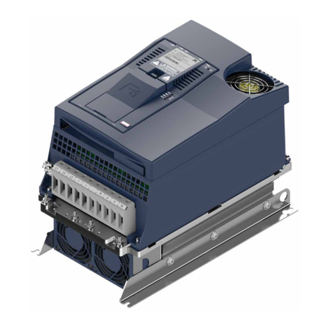
KEBCO COMBIVERT F5 Instructions for use

06/2002
Part.No.:00.F5.GEA-K230
Charge 40,- Euro
KEBCOMBIVERT F5-BASIC / GENERAL 2.3
APPLICATION MANUAL

1 1 Name:Basis
KEB COMBIVERT F5-G / B
228.02.02
Introduction General
© KEB Antriebstechnik, 2002
All Rights reserved
Chapter Section Page Date

3
113
28.02.02
KEB COMBIVERT F5-G / B
Name:Basis
1
Introduction
General
© KEB Antriebstechnik, 2002
All Rights reserved Chapter Section PageDate
Thischaptershallallowa fastaccesstothewantedinformation.Itconsistsofcontents,
index and search criterion.
Here the inverter and its features as well as the operating conditions and application
purpose are described.
Description ofhardware,technical data of the inverteraswell as connectionof power
and control terminals.
Thebasic operation of the KEB COMBIVERTlikepasswordinput, parameterandset
selection.
A list of all parameters classified according to parameter groups. The parameter
description comprises addresses, value ranges and references with regard to the
functions for which they are used.
To make the programming easier all inverter functions and the parameters belonging
to it are comprised in this chapter.
Gives support with regard to the initialstart-upandshowspossibilities andtechniques
for the optimization of the drive.
Describes special operating modes, like e.g. DC-coupling.
Avoidance of errors, evaluation of error messages and elimination of the causes.
Survey of the possible interconnection in existing networks;address and value table
for the implementation in own protocols.
Surveyof the possible interconnectionof the KEB COMBIVERT in existing networks.
Everything that didn’t fit anywhere else or what we didn’t think of earlier.
1. Introduction
2. Summary
3. Hardware
4. Operation
5. Parameter
6. Functions
7. Start-up
8. Special Operation
9. Error Assistance
10. Project Planning
11. Networks
12. Annex

Introduction
1 1 Name:Basis
KEB COMBIVERT F5-G / B
428.02.02 © KEB Antriebstechnik, 2002
All Rights reserved
Chapter Section Page Date

1.1 General
Introduction
1. Introduction
2. Summary
3. Hardware
4. Operation
5. Parameter
6. Functions
7. Start-up
8. Special Operation
9. Error Assistance
10. Project Planning
11. Networks
12. Annex
5
115
28.02.02
KEB COMBIVERT F5-G / B
Name:Basis
© KEB Antriebstechnik, 2002
All Rights reserved Chapter Section PageDate
1.1.1 Table of Contents ...................7
1.1.2 Preface ................................. 13
1.1.3 RecordofChanges ............... 15

1 1 Name:Basis
KEB COMBIVERT F5-G / B
628.02.02
Introduction General
© KEB Antriebstechnik, 2002
All Rights reserved
Chapter Section Page Date

7
117
28.02.02
KEB COMBIVERT F5-G / B
Name:Basis
1
Introduction
General
© KEB Antriebstechnik, 2002
All Rights reserved Chapter Section PageDate
1.1 General
1. Introduction
1.1.1 Table of Contents
1. Introduction............................................................................................ 1.1.7
1.1 General ................................................................................................1.1.7
1.1.1 Table of Contents ................................................................1.1.7
1.1.2 Preface.............................................................................. 1.1.13
1.1.3 Record of Changes ...........................................................1.1.15
2. Overview................................................................................................. 2.1.3
2.1 Product Description...........................................................................2.1.3
2.1.1 Features of KEB COMBIVERT............................................2.1.3
2.1.2 Function Principle ...............................................................2.1.3
2.1.3 Application as directed........................................................2.1.4
2.1.4 Type Code...........................................................................2.1.5
2.1.5 Validity of Specifications .....................................................2.1.6
2.1.6 Unit Sizes 230V-Class ........................................................ 2.1.6
2.1.7 Unit Sizes 400V-Class ........................................................ 2.1.7
2.1.8 Overload curve ..................................................................2.1.12
2.1.9 Overload protection in the lower speed range ...................2.1.12
3. Hardware ................................................................................................ 3.1.3
3.1 Control Units.......................................................................................3.1.3
3.1.1 Survey .................................................................................3.1.3
3.1.2 Terminal strip X2A ...............................................................3.1.4
3.1.3 Connection of the control.....................................................3.1.5
3.1.4 Digital inputs ......................................................................3.1.5
3.1.5 Analog inputs ......................................................................3.1.6
3.1.6 Voltage Input / External Power Supply ................................3.1.7
3.1.7 Digital Outputs.....................................................................3.1.7
3.1.8 Relay Outputs......................................................................3.1.7
3.1.9 Analog Outputs....................................................................3.1.8
3.1.10 Voltage Output.....................................................................3.1.8
4. Operation................................................................................................ 4.1.3
4.1 Fundamentals.....................................................................................4.1.3
4.1.1 Parameters, .........................................................................4.1.3
4.1.2 Selection of a Parameter .....................................................4.1.4
4.1.3 Adjustment of ParameterValues.......................................... 4.1.4
4.1.4 ENTER-Parameter ..............................................................4.1.4
4.1.5 Non-programmable Parameters ..........................................4.1.5
4.1.6 Resetting of Error Messages ...............................................4.1.5
4.1.7 Resetting of Peak Values.....................................................4.1.5
4.1.8 Acknowledgement of Status Signals...................................4.1.5

1 1 Name:Basis
KEB COMBIVERT F5-G / B
828.02.02
Introduction General
© KEB Antriebstechnik, 2002
All Rights reserved
Chapter Section Page Date
4.2 Password Structure ........................................................................... 4.2.3
4.2.1 Password Levels .................................................................4.2.3
4.2.2 Passwords...........................................................................4.2.4
4.2.3 Changing of Password Level...............................................4.2.4
4.3 CP-Parameter .....................................................................................4.3.3
4.3.1 Operation in CP-Mode.........................................................4.3.3
4.3.2 FactorySetting ....................................................................4.3.4
4.3.3 Password Input.................................................................... 4.3.5
4.3.4 Operating Display................................................................ 4.3.5
4.3.5 Basic Adjustment of the Drive.............................................4.3.7
4.3.6 Special Adjustments..........................................................4.3.10
4.4 Drive-Mode.......................................................................................... 4.4.3
4.4.1 Adjustment Possibilities ...................................................... 4.4.3
4.4.2 Display and Keyboard .........................................................4.4.3
4.4.3 Setpoint Display /Setpoint Input ..........................................4.4.3
4.4.4 Rotation Setting...................................................................4.4.4
4.4.5 Start / Stop / Run .................................................................4.4.4
4.4.6 Leaving the Drive-Mode ......................................................4.4.5
4.4.7 Further Settings...................................................................4.4.5
5. Parameter ............................................................................................... 5.1.3
5.1 Parameter............................................................................................ 5.1.3
5.1.1 ParameterGroups ...............................................................5.1.3
5.1.2 F5-BASIC Control ...............................................................5.1.4
5.1.3 F5-GENERAL Control B-housing........................................5.1.4
5.1.4 F5-GENERAL Control >= D-housing .................................. 5.1.5
5.1.5 Parameter Listing ................................................................5.1.7
6. Functional Description ......................................................................... 6.1.3
6.1 Operating and Appliance Data .......................................................... 6.1.3
6.1.1 Overview of the ru-Parameters ...........................................6.1.3
6.1.2 Overview of the In-Parameters.............................................6.1.4
6.1.3 Overview of the Sy-Parameters ...........................................6.1.4
6.1.4 Explanation to Parameter Description ................................. 6.1.5
6.1.5 Description of the ru-Parameters .........................................6.1.6
6.1.6 Description of the In-Parameters .......................................6.1.17
6.1.7 Description of the Sy-Parameters ......................................6.1.21
6.2 Analog In- and Outputs...................................................................... 6.2.3
6.2.1 Summary Description Analog Inputs ...................................6.2.3
6.2.2 Interface Selection (An.0; An.10) .........................................6.2.4
6.2.3 Interference Suppression Filter (An.1; An.11; An.21) ...........6.2.5
6.2.4 Save Mode (An.2; An.12; An.22)..........................................6.2.5
6.2.5 Input Selection (An.3; An.13; An.23) .................................... 6.2.5
6.2.6 Zero Point Hysteresis (An.4; An.14; An.24)..........................6.2.6
6.2.7 Amplifierof theInput Characterstic (An.5...7;An.15...17;
An.25...27) ...........................................................................6.2.7
6.2.8 Lower and Upper Limit (An.8/9; An.18/19; An.28/29)...........6.2.8

9
119
28.02.02
KEB COMBIVERT F5-G / B
Name:Basis
1
Introduction
General
© KEB Antriebstechnik, 2002
All Rights reserved Chapter Section PageDate
6.2.9 Selection Set Point-/Auxiliary Input (An.30)......................... 6.2.9
6.2.10 Brief Description Analog Outputs ......................................6.2.10
6.2.11 Output signals ...................................................................6.2.11
6.2.12 Analog Output / Functions (An.31/An.36/An.41)...............6.2.11
6.2.13 Analog Output / Display.....................................................6.2.12
6.2.14 Gainof Output Characteristic(An.33...35 /An.38...40 /
An.43...45) .........................................................................6.2.12
6.2.15 Period ANOUT3 (An.46)....................................................6.2.13
6.2.16 ANOUT 1...4 Digital Settings (An.32/37/42/48) .................6.2.13
6.2.17 Used Parameters..............................................................6.2.14
6.3 Digital In- and Outputs .......................................................................6.3.3
6.3.1 Summary Description Digital Inputs ....................................6.3.3
6.3.2 Input Signals PNP / NPN (di.0) ...........................................6.3.3
6.3.3 Setting of Digital Inputs by Software (di.1, di.2) ...................6.3.4
6.3.4 TerminalStatus (ru.21) ........................................................6.3.5
6.3.5 Digital Filter (di.3) ................................................................6.3.5
6.3.6 Inversion of Inputs (di.4) ......................................................6.3.5
6.3.7 Edge-triggering (di.5)...........................................................6.3.5
6.3.8 Strobe-dependent Inputs (di.6, di.7, di.8).............................6.3.6
6.3.9 InputStatus (ru.22) ..............................................................6.3.8
6.3.10 Reset/Input Selection and Edge Evaluation
(di.9 / di.10)..........................................................................6.3.8
6.3.11 Assignment of the Inputs .....................................................6.3.8
6.3.12 Summary Description - Digital Outputs.............................. 6.3.11
6.3.13 Output Signals...................................................................6.3.12
6.3.14 Outputfilter (do.43,do.44)..................................................6.3.12
6.3.15 Switching Conditions (do.0...do.7) .....................................6.3.13
6.3.16 Inverting of Switching Conditions for Flags (do.8...do.15)..6.3.16
6.3.17 Selection of Switching Conditions for Flags (do.16...do.23)6.3.16
6.3.18 Linking the Switching Conditions for Flags (do.24) ...........6.3.16
6.3.19 Inverting of Flags (do.25...do.32) .......................................6.3.17
6.3.20 Selection of Flags (do.33...do.40) ......................................6.3.17
6.3.21 Linking the Flags (do.41) ...................................................6.3.17
6.3.22 Inversion of Outputs (do.42)...............................................6.3.18
6.3.23 OutputTerminalStatus (ru.25) ...........................................6.3.18
6.3.24 Programming Example...................................................... 6.3.19
6.3.25 Used Parameters...............................................................6.3.20
6.4 Setpoint-, Rotation- and Ramp Adjustment .....................................6.4.3
6.4.1 Summary Description ..........................................................6.4.3
6.4.2 Setpoint Selection oP.0 .......................................................6.4.4
6.4.3 Rotation Selection oP.1 .......................................................6.4.6
6.4.4 Fixed Frequencies (oP.18...23) ............................................6.4.9
6.4.5 Setpoint Limits...................................................................6.4.11
6.4.6 Setpoint Computation........................................................6.4.12
6.4.7 Ramp Generator................................................................ 6.4.13

1 1 Name:Basis
KEB COMBIVERT F5-G / B
10 28.02.02
Introduction General
© KEB Antriebstechnik, 2002
All Rights reserved
Chapter Section Page Date
6.4.8 Limiter(oP.36...41).............................................................6.4.15
6.4.9 Ramp with constant time ...................................................6.4.15
6.4.10 Used Parameters...............................................................6.4.18
6.5 Voltage-/Frequency Characteristic Adjustment............................... 6.5.3
6.5.1 ControlType (ud.2) and Max Frequency Mode (only F5-B)..6.5.3
6.5.2 Rated frequency (uF.0) and Boost (uF.1) .............................6.5.4
6.5.3 Additional Rated Point (uF.2/uF.3) .......................................6.5.4
6.5.4 Delta Boost (uF.4/uF.5) ........................................................6.5.4
6.5.5 Voltage Stabilization (uF.9)..................................................6.5.5
6.5.6 Maximal voltage mode (uF.10)............................................. 6.5.6
6.5.7 Switching Frequency (uF.11) ............................................... 6.5.6
6.5.8 Used Parameters.................................................................6.5.7
6.6 Motor Data Adjustment ......................................................................6.6.3
6.6.1 Motor Name Plate................................................................ 6.6.3
6.6.2 MotorData from theName Plate (dr.0...dr.5)........................6.6.3
6.6.3 Motor Data from Data Sheets (dr.9).....................................6.6.4
6.6.4 MotorStator Resistance (dr.6) ............................................. 6.6.4
6.6.5 Used Parameters.................................................................6.6.6
6.7 Protective Functions.......................................................................... 6.7.3
6.7.1 Ramp Stop and Hardware Current Limit..............................6.7.3
6.7.2 Current Limit Constant Run (Stall-Function)........................ 6.7.5
6.7.3 Automatic Restart and Speed Search .................................6.7.7
6.7.4 Dead Time Compensation uF.18.........................................6.7.9
6.7.5 Base-Block Time (uF.12) and Voltage Level (uF.13) ............6.7.9
6.7.6 Response to Errors or Warning Signal ................................6.7.9
6.7.7 QuickStop (Pn.58...60) .....................................................6.7.13
6.7.8 Motor Protection Mode ......................................................6.7.15
6.7.9 GTR7-Control....................................................................6.7.19
6.7.10 Special Functions..............................................................6.7.20
6.8 Parameter Sets ...................................................................................6.8.3
6.8.1 Not Programmable Parameters ...........................................6.8.3
6.8.2 Security-Parameters ............................................................6.8.3
6.8.3 System-Parameters .............................................................6.8.3
6.8.4 Indirect and Direct Set Addressing ......................................6.8.3
6.8.5 Copying of Parameter Sets via Keyboard (Fr.1) ...................6.8.4
6.8.6 Copying of Parameter Sets via Bus (Fr.1, Fr.9) ....................6.8.4
6.8.7 Parameter Set Selection...................................................... 6.8.5
6.8.8 Locking of Parameter Sets...................................................6.8.8
6.8.9 ParameterSet ON/Off Delay(Fr.5, Fr.6) ...............................6.8.8
6.8.10 Used Parameters.................................................................6.8.9
6.9 Special Functions .............................................................................. 6.9.3
6.9.1 DC-Braking .........................................................................6.9.3
6.9.2 Energy Saving Function......................................................6.9.5
6.9.3 Motor Potentiometer Function..............................................6.9.7
6.9.4 Timer and Counter ............................................................6.9.11
6.9.5 Brake Control ....................................................................6.9.15

11
1111
28.02.02
KEB COMBIVERT F5-G / B
Name:Basis
1
Introduction
General
© KEB Antriebstechnik, 2002
All Rights reserved Chapter Section PageDate
6.9.6 Power-Off Function............................................................6.9.19
6.9.7 Wobbel Function ...............................................................6.9.27
6.9.8 Diameter Correction ..........................................................6.9.29
6.9.9 Positioning Function..........................................................6.9.31
6.9.10 Analog setting of parameter values ...................................6.9.34
6.10 Encoder Interface.............................................................................6.10.3
6.10.1 Designs.............................................................................6.10.3
6.10.2 Encoder Interface Channel 1 (X3A)...................................6.10.4
6.10.3 Encoder Inteface Channel 2(X3B)....................................6.10.5
6.10.4 Power Supply of Encoder..................................................6.10.7
6.10.5 Selection of Encoder .........................................................6.10.8
6.10.6 Basic Setting ...................................................................6.10.10
6.10.7 Additional Parameters .....................................................6.10.13
6.10.8 Used Parameters.............................................................6.10.14
6.11 SSM ...................................................................................................6.11.3
6.11.1 Torque Compensation .......................................................6.11.3
6.11.2 Speed Control ...................................................................6.11.4
6.11.3 Used Parameters...............................................................6.11.6
6.12 Technology Controller .....................................................................6.12.3
6.12.1 The PID Controller ............................................................6.12.3
6.12.2 PID Setpoint Value ............................................................6.12.5
6.12.3 PID Actual Value ...............................................................6.12.6
6.12.4 Sample Applications .........................................................6.12.7
6.12.5 Used Parameters.............................................................6.12.10
6.13 CP-Parameter Definition .................................................................. 6.13.3
6.13.1 Survey ...............................................................................6.13.3
6.13.2 Assignment of CP-Parameters ..........................................6.13.4
6.13.3 Example ............................................................................6.13.5
6.13.4 Display Standardization ....................................................6.13.6
6.13.5 Used Parameters...............................................................6.13.8
7. Start-up .......................................................................................................... 7.1.3
7.1 Preparatory Measures........................................................................7.1.3
7.1.1 After unpacking the Goods ..................................................7.1.3
7.1.2 Installation and Connection.................................................7.1.3
7.1.3 Checklist prior to Start-up....................................................7.1.4
8. Special Operations................................................................................ 8.1.2
9. Error Assistance.................................................................................... 9.1.3
9.1 Troubleshooting ................................................................................. 9.1.3
9.1.1 General ...............................................................................9.1.3
9.1.2 Error Messages and their Cause.........................................9.1.3
10. Project Planning .................................................................................. 10.1.3
10.1 General Design .................................................................................10.1.3
10.1.1 Control Cabinet Design Calculation..................................10.1.3
10.1.2 Design of Braking Resistors..............................................10.1.4
10.1.3 Cable and Fuses...............................................................10.1.6

1 1 Name:Basis
KEB COMBIVERT F5-G / B
12 28.02.02
Introduction General
© KEB Antriebstechnik, 2002
All Rights reserved
Chapter Section Page Date
11. Networks............................................................................................... 11.1.3
11.1 Network Components ......................................................................11.1.3
11.1.1 Available Hardware...........................................................11.1.3
11.1.2 RS232-Cable PC /Operator 00.58.025-001D....................11.1.3
11.1.3 HSP5-Cable PC / Control Board 00.F5.0C0-0001 ...........11.1.3
11.1.4 Interface-Operator00.F5.060-2000 ...................................11.1.4
11.1.5 Profibus-DP-Operator 00.F5.060-3000..............................11.1.5
11.1.6 InterBusOperator 00.F5.060-4000 ....................................11.1.6
11.1.7 CanOpen Operator 00.F5.060-5000..................................11.1.7
11.1.8 Sercos Operator 00.F5.060-6000 ......................................11.1.8
11.2. Bus Parameters................................................................................11.2.3
11.2.1 Adjustment of Inverter Address (Sy.6)................................11.2.3
11.2.2 Baud Rate ext.Bus (Sy.7)..................................................11.2.3
11.2.3 Baud Rate int.Bus (Sy.11).................................................11.2.3
11.2.4 Watchdog-Time(Pn.6).......................................................11.2.3
11.2.5 Response to E.bus (Pn.5) .................................................11.2.3
11.2.6 HSP5 WatchdogTime (sY.9) .............................................11.2.3
11.2.7 Control and StatusWord ...................................................11.2.4
11.2.8 Speed Setting via Bus.......................................................11.2.5
11.2.9 Used Parameters...............................................................11.2.6
12. Annex.................................................................................................... 12.1.3
12.1 Search and Find ...............................................................................12.1.3
12.1.1 Index .................................................................................12.1.3
12.1.2 KEB- Worldwide ................................................................12.1.7
12.1.3 Domestic Representations ................................................12.1.9

13
1113
28.02.02
KEB COMBIVERT F5-G / B
Name:Basis
1
Introduction
General
© KEB Antriebstechnik, 2002
All Rights reserved Chapter Section PageDate
Who shall read all this?
Everybodywhoisentrusted with the developmentandconstructionofapplications.
He who knows the extensiveprogramming possibilities of the KEB COMBIVERT,
cansave external controls andexpensive cabling alreadyin the planning stageof
a machine simply by using the unit as active control element.This manual is not
a replacement of the documentation accompanying the unit, it serves only as
completion.
1000 and one application...
and if possible with one unit. Who does not know this demand from purchasing
departments, production or service. We have taken this request very seriously
and developed a series with open programming, which can be adapted to the
different applications with PC oroperator.
Nobody can handle this...
some sceptics may say. But we have found a solution to this too. Once the
development stage of a machine is completed only a few adjustment possibilities
are needed on the inverter and in some cases even none at all.So why should all
parametersstillbevisible?Said anddone,bydefining an ownmenuonly selected
parameters are visible.This makes the handling much easier, simplifies the user
documentationand improves the safety of operationagainst unauthorizedaccess
(see picture 1.1.2).
1.1.2 Preface
Picture 1.1.2
Entire parameter pool
User menu
(CP-Parameters)

Introduction
1 1 Name:Basis
KEB COMBIVERT F5-G / B
14 28.02.02 © KEB Antriebstechnik, 2002
All Rights reserved
Chapter Section Page Date

15
1115
28.02.02
KEB COMBIVERT F5-G / B
Name:Basis
1
Introduction
General
© KEB Antriebstechnik, 2002
All Rights reserved Chapter Section PageDate
* Typ: (B)ase; (N)ew; Chang(e); (A)ddition
No. Typ*) Date Name Description
1.1.3 Record of Changes

1 1 Name:Basis
KEB COMBIVERT F5-G / B
16 28.02.02
Introduction General
© KEB Antriebstechnik, 2002
All Rights reserved
Chapter Section Page Date

2.1 Product Description
Summary
1. Introduction
2. Summary
3. Hardware
4. Operation
5. Parameter
6. Functions
7. Start-up
8. Special Operation
9. Error Assistance
10. Project Planning
11. Networks
12. Annex
1
211
KEB COMBIVERT F5
Name: Basis
10.04.02
© KEB Antriebstechnik, 2002
All Rights reserved Section PageDate Chapter
2.1.1 Features of
KEB COMBIVERT.................. 3
2.1.2 Function Principle................... 3
2.1.3 Application as directed ...........4
2.1.4 Type Code .............................. 5
2.1.5 Validity of Specifications......... 6
2.1.6 Unit Sizes 230V-Class............6
2.1.7 Unit Sizes 400V-Class............7
2.1.8 Overloadcurve ..................... 12
2.1.9 Overloadprotection in the lower
speedrange.......................... 12

21KEB COMBIVERT F5
2Name: Basis
10.04.02 © KEB Antriebstechnik, 2002
All Rights reserved
Product DescriptionSummary
Chapter Section Page Date

3
213
KEB COMBIVERT F5
Name: Basis
10.04.02
2
© KEB Antriebstechnik, 2002
All Rights reserved
Product Description Summary
Section PageDate Chapter
L1
L2
(L3)
2.1.1 Features of KEB
COMBIVERT
2.1 Product Description
KEB
COMBIVERT
8 parameter sets
14 parameter groups
Prog.Operator menu
2 prog.relay outputs
8 prog. digital inputs
2 prog. digital output
2 prog. analog output
2 prog. analog inputs
Hardware current limit
Autoboost
Slip compensation
DC-braking
Jogging-function (prog.)
Speed search
Power-Off function
HSP5 interface
Energy saving function
PID-controller
Protectiveequipment
Electr.motor protection
Prog.filter for analog and digital inputs
Software In-/Outputs
Adjustable balancing of the ramps
Hour meter
2.1.2 Function
Principle The power circuit of a frequency inverter consists basically of a mains rectifier, the
DC-link and an inverter at the output.The mains rectifier consists of an uncontrolled
singleorthree-phase bridge connection,thesingle-phasedesign is restrictedto small
powers.It convertsthe AC-voltage of themains into a DC-voltage, which issmoothed
by the DC-link capacitor, thus in the ideal case (inverter unloaded) the DC-link is
charged with a voltage of UZK = √2 .UN.
Since during the charging of the DC-link capacitor very high currents flow for a short
time which would lead to the tripping of the input fuses or even to the destruction of
the mains rectifier, the charging current must be limited to a permissible level.This is
achieved by using an inrush current limiting resistor in series to the capacitor. After
thecharging of the capacitor iscompleted the limiting resistor isbridged, forexample,
by a relay and is therefore only active at the switch-on of the inverter.
As the smoothing of the DC-link voltage requires a large capacity, the capacitor still
has a high voltage for some time after the disconnection of the inverter from the
mains.
The actual task of the frequency inverter, to produce an output voltage variable in
frequencyand amplitude for the control of the three-phase AC motor, is taken over by
the converter at the output.It makes available a 3-phase output voltage according to
the principle of the pulse-width modulation, which generates a sinusoidal current at
the three-phase asynchronous motor
Picture 2.1.2 Block diagram of an inverter power circuit
2. Overview
Encoder interface
=
~=
~
UNRCW
U
VUZK
Mains rectifier MotorConverterDC-link

21KEB COMBIVERT F5
4Name: Basis
10.04.02 © KEB Antriebstechnik, 2002
All Rights reserved
Product DescriptionSummary
Chapter Section Page Date
2.1.3 Application as directed
TheKEBCOMBIVERT is afrequencyinverterwithDC-voltage
link. It works according to the principle of the pulse-width
modulation and serves exclusively for the stepless speed
control of three-phase AC motors.
The unit has been developed subject to the relevant safety
standards and is manufactured with the highest demands on
quality. Condition for an unobjectionable operation is the
function-conformconfiguringofthedriveandcorrecttransport
and storage as well as careful installation and connection.
The operation of other electric consumers is prohibited and
canleadtothe destructionof the units aswellas consequential
damages as a result from it.
Other manuals for COMBIVERT F5
48
This manual suits for next models
3
Table of contents
Other KEBCO Industrial Electrical manuals
Popular Industrial Electrical manuals by other brands

Murata
Murata GRM0335C1H5R1DA01 Series Reference sheet

Beckhoff
Beckhoff KL2692 Documentation

Murata
Murata GRM0335C1E3R6BA01 Series Reference sheet

Murata
Murata GRM1557U1A132JA01 Series Reference sheet

Murata
Murata GQM22M5C2H7R0DB01 Series Reference sheet

Murata
Murata GRM1555C1E1R2BA01 Series Reference sheet

Murata
Murata GRM1885C1H4R7CA01 Series Reference sheet

Siemens
Siemens SIRIUS 3RH14 1 Series operating instructions

Eaton
Eaton Power Defense NZM-XBZ225 Instruction leaflet

Murata
Murata GQM1885C1H100JB01 Series Reference sheet

Campbell
Campbell CS230 product manual

Elektro-Automatik
Elektro-Automatik ELR 9000 HP operating manual