Keeper KWSL2000RM Quick reference guide

Hampton Products International Corp.
50 Icon
Foothill Ranch, CA 92610
800-533-7372
™
CAUTION!
READ AND UNDERSTAND THIS MANUAL BEFORE INSTALLATION
AND OPERATION OF THIS PRODUCT.
DO NOT RETURN THIS PRODUCT TO SELLER. CALL KEEPER
WINCH AT 800-533-7372 FOR ASSISTANCE
Assembly & Operating Instructions
KWSL2000RM
2000 Lb. 12VDC Electric Winch
! !

KWSL2000RM 2000 lb. 12VDC Electric Winch
THIS PRODUCT IS NOT INTENDED FOR LIFTING / HOISTING
! !
Save this Manual
You will need this manual for the safety warnings and cautions, assembly instructions, operating proce-
dures, maintenance procedures, trouble shooting, parts list, and diagram. Keep your invoice with this
manual. Write the invoice number on the inside of the front cover. Keep both this manual and your invoice
in a safe, dry place for future reference.
KWSL2000RM WINCH SPECIFICATIONS
Capacity
Max Boat Size:
Max Boat Weight:
Line Speed:
Current Draw
Cable Length:
Hook Size:
Power Supply
Power Cord:
Remote Switch
RAPID MOUNT Plate:
Winch Dimensions:
Net Weight:
6000 lb. Rolling Load
5000 lb. Boat fully loaded up to 18’ long
2000 lb. Pulling Capacity
18 Feet
5000 lb.
6 Feet/Minute with Load
6 Amps @ 150 lbs.
20 Amps @ 2,000 lbs.
30 Feet
3/4” Opening x 3-3/4” L.
12 Volts DC
6’ Long Negative Lead with attachment clip
20’ Long Positive Lead with attachment clip
On 10’ lead
8-3/4” x 4-15/16” x 3/16”
9-1/2” x 7-1/2” x 10”
24 lbs.
Pulling capacity of winch is rated on rst layer of wire rope on the drum. As you accumulate layers
your pulling capacity will diminish by 10-15% per layer.
2
Designed for Marine and Utility Recovery, Boats up to 18’ and General Utility Winching Applications.
THIS PRODUCT IS NOT INTENDED FOR LIFTING/HOISTING
Assembly & Operating Instructions
CAUTION
PLEASE READ ALL SAFETY PRECAUTIONS AND WARNINGS BEFORE
INSTALLING AND USING THE WINCH! IF YOU HAVE QUESTIONS PLEASE
CALL 1 800-533-7372
Introduction
Thank you for purchasing your KEEPER®Winch.
PLEASE READ ALL INSTRUCTIONS, PAYING SPECIAL ATTENTION TO THE
SAFETY INSTRUCTIONS.
Thank you for purchasing a KEEPER WINCH. We hope you will be pleased with your purchase. Your winch
was designed for non-industrial use. As with any power tool there is a potential for personal injury if your
winch is improperly installed or operated. It is extremely important that anyone operating this winch reads
and understands this manual prior to installing and operating this winch.

Included Accessories
1. Power Lead, tted with water sealed plug and circuit breaker
2. Remote Switch with water sealed plug for safe operation
3. 30’ Aircraft Cable with attached hook with latch
4. RAPID MOUNT Bracket for Trailer Hitch Ball
5. Emergency Crank Handle
6. HANDSAVER Strap
THIS PRODUCT IS NOT INTENDED FOR LIFTING / HOISTING
1 Convenient, portable power for pulling boats, self recovery and other heavy loads.
2 Powerful 2,000 lb. single line pulling power.
3 12 Volt DC.
4 Portable, with built-in carrying handle, easy to connect wiring harness, handheld remote and Rapid
Mount Ball Hitch Plate.
Product Features
Notice
The Warnings, cautions, and Instructions discussed in this instruction manual cannot cover all possible
conditions and situations that may occur. It must be understood by the operator that common sense and
caution are factors which cannot be built into this product, but must be supplied by the operator.
SAFETY WARNING & CAUTIONS
WARNING: When using any power equipment, basic safety
precautions should always be followed to reduce the risk of
personal injury and hazards.
READ ALL INSTRUCTIONS BEFORE USING THIS WINCH!
! !
WARNING
Your KEEPER® Winch is a very powerful machine. If used unsafely or improperly, serious personal injury
and/or property damage can result.
3
FIGURE 1

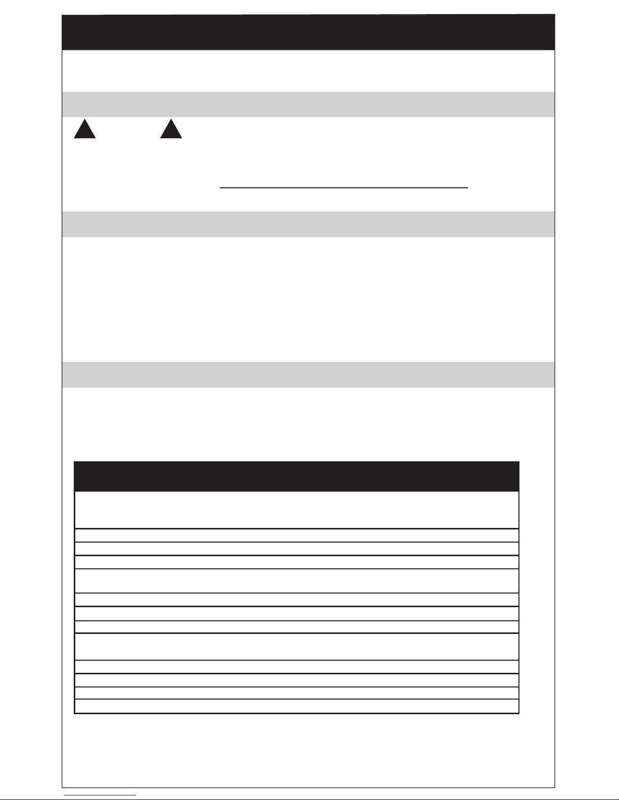
Double Line Single Line
FIGURE 2
1. READ AND UNDERSTAND THIS MANUAL BEFORE OPERATING YOUR WINCH. After installing the Winch,
practice using it before the need arises. NEVER ALLOW PERSONS UNFAMILIAR WITH THIS PRODUCT
TO OPERATE IT. ALWAYS WEAR SAFETY GLASSES WHILE WORKING WITH MACHINERY.
2. DO NOT EXCEED RATED CAPACITY OF THE WINCH. DO NOT OVERLOAD! DO NOT ATTEMPT
PROLONGED PULLS OF HEAVY LOADS!
Overloads can damage the Winch and/
or the wire rope and create unsafe
operating conditions. FOR LOADS OVER
75% OF THE RATED WINCH CAPACITY,
WE RECOMMEND THE USE OF A PULLEY
BLOCK (KTA15120 not included) TO
DOUBLE LINE THE WIRE ROPE . (Figure
2). This reduces the load on the Winch, the
strain on the wire rope and electrical system.
3. Never apply a load to your winch with the wire rope fully extended. Keep at least 5 turns on the
winch drum.
4. THE VEHICLE ENGINE SHOULD BE RUNNING DURING WINCH OPERATION. If winching is performed
with the engine turned off, the battery may be too weak to restart the engine.
5. DO NOT operate your vehicle to assist the Winch in pulling the load. The combination of the Winch and
vehicle pulling together could overload the wire rope and the Winch.
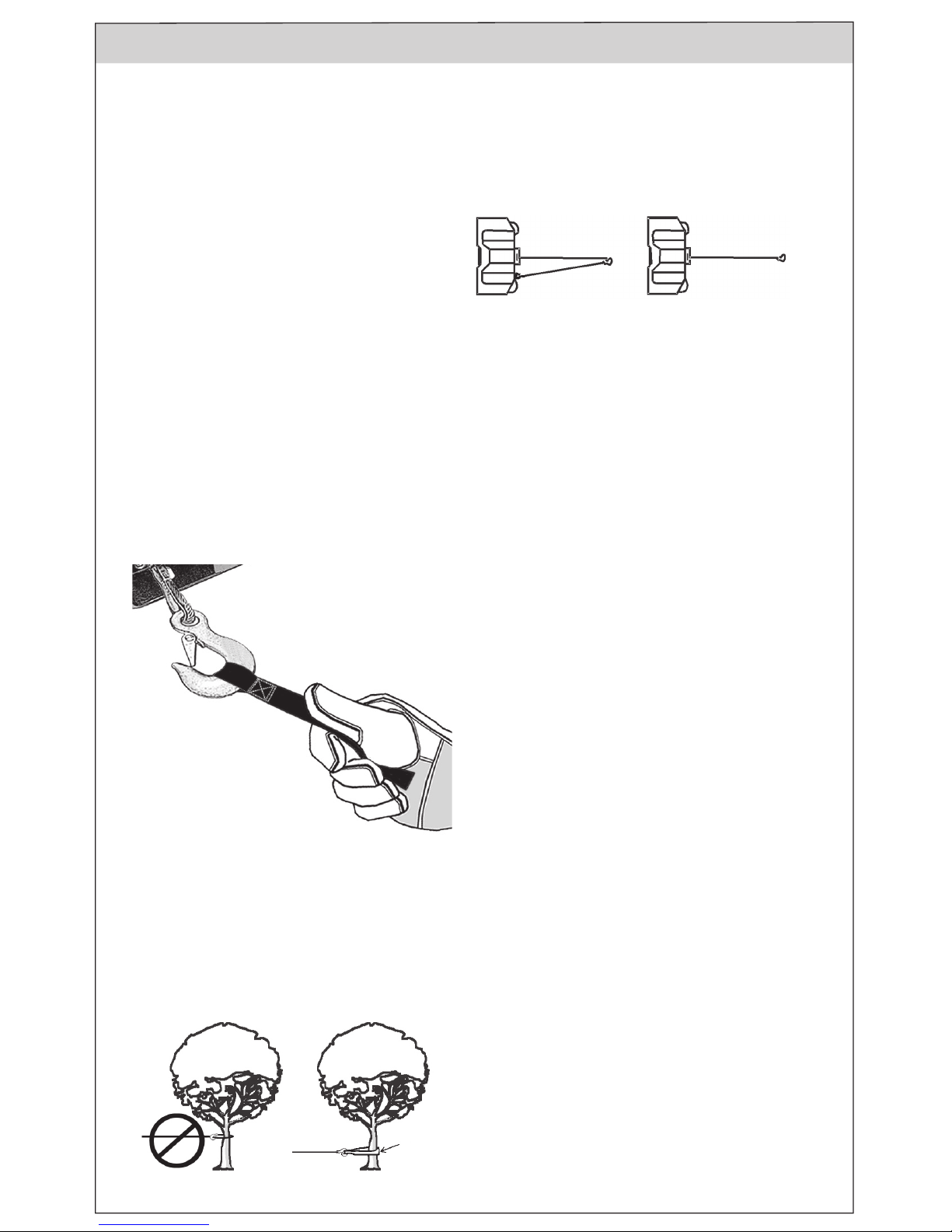
Sling
FIGURE 4
4
Safety Warnings & Cautions (Continued)
FIGURE 3
6. WHEN IN USE, ALWAYS STAND CLEAR OF WIRE
ROPE, HOOK AND WINCH.
7. INSPECT WIRE ROPE AND EQUIPMENT
FREQUENTLY. A FRAYED, KINKED OR FLATTENED
WIRE ROPE NEEDS TO BE REPLACED
IMMEDIATELY. Periodically check the Winch
installation to ensure that all bolts are tight.
8. USE HEAVY LEATHER GLOVES when handling wire
rope. DO NOT LET WIRE ROPE SLIDE THROUGH
YOUR GLOVED OR UNGLOVED HANDS. ALWAYS
USE THE HAND-SAVER STRAP when guiding the
wire rope in or out (Figure 3).
9. NEVER WINCH WITH LESS THAN 5 WRAPS OF
WIRE ROPE AROUND THE WINCH DRUM since the
wire rope end fastener may NOT withstand
full load.
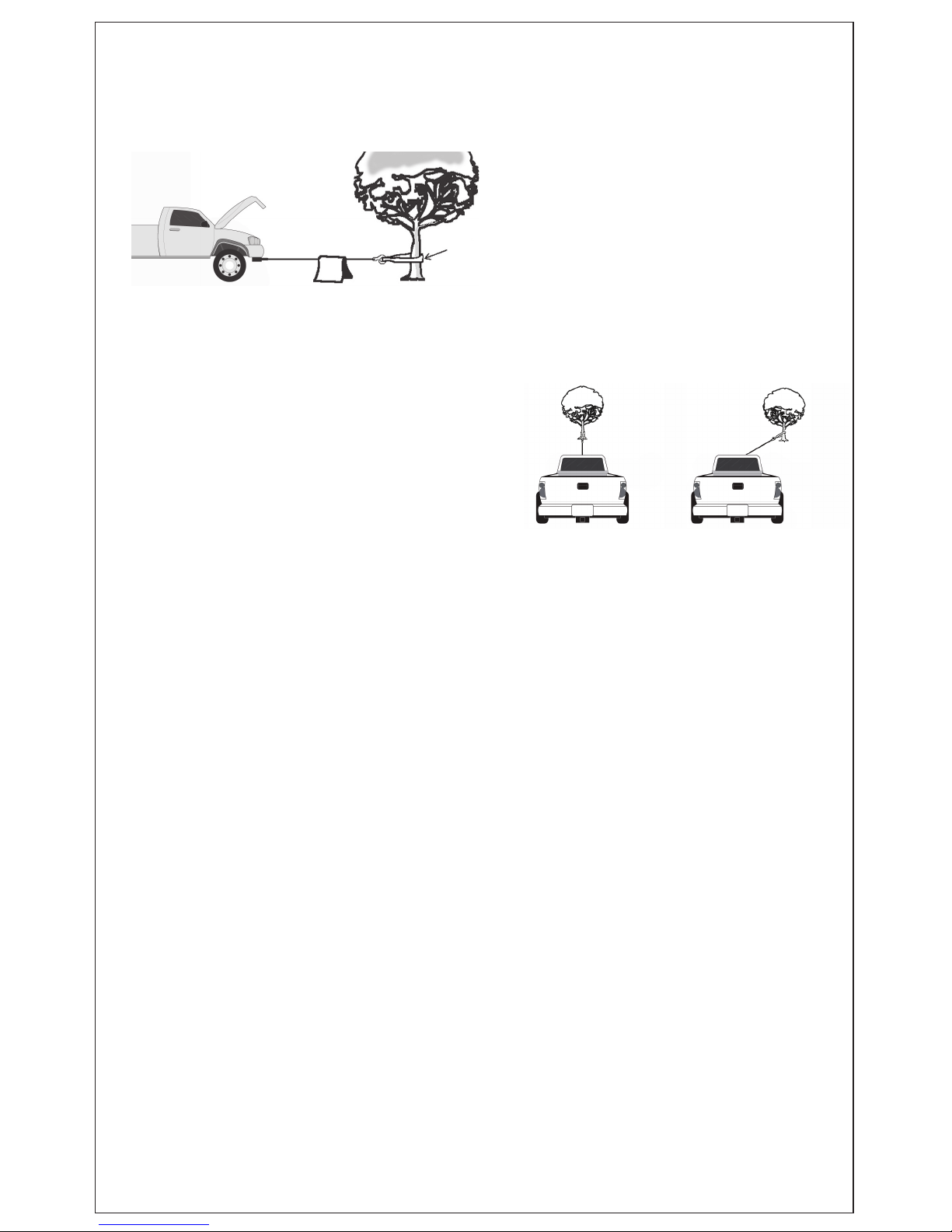
12. It is highly recommended to lay a heavy cloth
(such as a blanket or tarp) over the wire rope
when pulling heavy loads (Figure 5). If a wire
rope failure should occur, the cloth will act as
a damper and help prevent the wire rope from
whipping. If mounted on the front of a vehicle
then raise the hood for further protection.
13. NEVER USE YOUR WINCH FOR LIFTING OR
MOVING PEOPLE!
10.KEEP CLEAR OF WINCH, TAUT WIRE ROPE AND HOOK WHEN OPERATING WINCH. NEVER STEP OVER
TAUT WIRE ROPE.
11.NEVER HOOK THE WIRE ROPE BACK ONTO ITSELF. This will damage the wire rope. Use a KEEPER
WINCH STRAP, sling, tree saver or other recommended accessory for this type connection (Figure 4).

14. OUR WINCH IS NOT INTENDED FOR OVER
HEAD HOISTING OPERATIONS.
15. AVOID CONTINUOUS PULLS FROM
EXTREME ANGLES. This will cause the
wire rope to pileup on one end of the drum
(Figure 6). This can jam the wire rope in the
Winch, causing damage to the wire rope or
Winch.
16. NEVER OBSCURE THE WARNING
INSTRUCTION LABELS ON THE WINCH.
17. Always operate Winch with an unobstructed
view of the Winching operation.
18. Equipment such as hooks, pulley blocks, straps, etc.
should be sized for winch capacity and periodically
inspected for damage that could reduce their strength.
19. NEVER RELEASE FREESPOOL CLUTCH WHEN THERE
IS A LOAD ON THE WINCH.
20. NEVER WORK ON OR AROUND THE WINCH DRUM
WHEN WINCH OR WIRE ROPE IS UNDER LOAD.
21. DO NOT OPERATE WINCH WHEN UNDER THE INFLUENCE OF ANY DRUGS OR ALCOHOL.
22. ALWAYS DISCONNECT WINCH POWER LEADS TO BATTERY BEFORE WORKING ON OR AROUND THE
WINCH DRUM so that Winch cannot be turned on accidentally.
23. When moving a load, slowly take up wire rope slack until it is taut. Stop, recheck all Winching
connections. Be sure the hook is properly seated. If a nylon sling is used, check the attachment to
the load.
24. When using a vehicle mounted Winch to move a load, place the vehicle transmission in neutral (never in
Park), set vehicle hand-brake, and chock all wheels.
25. DO NOT USE THE WINCH TO HOLD LOADS IN PLACE. Use other means of securing loads such as
KEEPER brand tie-down straps. For tie-down information go to www.keepercorp.com
26. USE ONLY FACTORY APPROVED SWITCHES, ADAPTERS, REMOTE CONTROLS AND
ACCESSORIES. Use of non-factory approved components may cause injury or property damage
and could void your warranty.
27. DO NOT MACHINE OR WELD ANY PART OF THE WINCH. Such alteration may weaken the structural
integrity of the Winch and could void your warranty.
28. This is a 12 Volt DC Winch. CONNECT ONLY TO 12 VOLT DC BATTERY. DO NOT CONNECT WINCH TO
EITHER 110V OR 220V AC CURRENT AS WINCH WILL BURN OUT OR FATAL SHOCK WILL OCCUR.
This will void warranty.
29. Never allow shock loads to be applied to Winch or wire rope.
30. Use extreme caution when winching a load up and down a ramp or incline.
31. Keep people, other than operator, pets, and property clear of Winching path, front, rear and sides for 60’
32. The Hand Crank provided with your winch is for emergency use only (i.e. in case of battery failure).
Never use the Hand Crank to assist your winch when it is running. Always remove the Hand Crank
when your winch is not in use. Do Not operate your winch or allow your winch to freewheel with the
Hand Crank INSTALLED.
Sling
FIGURE 5
5
FIGURE 6

The Cable Be sure the cable is in good condition and is attached properly. Do not use the winch if
the cable is frayed. Do not replace the cable with a cable of lesser strength.
The Battery Be sure the battery is in good condition. Avoid contact with battery acid or other con-
taminants. Always wear ANSI approved eye protection when working around a battery.
Have the engine running when using the winch to avoid running the battery down.
Stand Back Stay out of the direct line that the cable is pulling. In case it slips or breaks, it will
“whiplash” along this line. Keep hands, clothing, hair and jewelry clear of the winch
while in use. Use a spotter to assist you in assuring that it is safe to operate the
winch. Make sure this person is out of the way of the vehicle and the cable before
activating the winch.
Power Limits Do not attempt to exceed the pulling limits of this winch. Never use the hand crank to
“assist” the winch. This will damage the winch and may cause personal injury.
Permanent Mounting
1. Select a mounting site on the bumper of your vehicle, truck bed, boat trailer, or other suitable location.
NOTE: This winch can generate 2,000 lbs. pulling force. Be sure the location you select can withstand this
much force.
2. Align the winch with the desired location and mark for drilling the locations of the 3 holes on the base
of the winch.
3. Drill these holes where you wish to mount the winch on a stable structural support location on your vehicle
or trailer (Figure 7).
4. Using hardened steel bolts at least 3/8” in diameter, install your winch to the location.
SPECIAL WARNINGS WHEN USING THIS ELECTRIC WINCH
Using this powerful tool may create special hazards. Take
particular care to safeguard yourself and those around you.
INSTALLATION - Mounting Your Winch
Your winch is designed to be mounted temporarily using the RAPID MOUNT Ball
Trailer Hitch Mounting Plate. However, you may also mount your winch permanently
6
! !
WARNING
FIGURE 7

Temporary Mounting
1. Attach the (3) Plate Stud Bolts to the Adapter Plate (Figure 8), as shown, using the supplied nuts.
Tighten securely.
2. Insert the heads of the Plat Studs into the keyhole slots on the back of the winch.
3. Attach the Winch/Adapter Plate assembly to your trailer hitch by inserting the trailer hitch ball through the
shaped hole in the Adapter Plate (Figure 9).
STUD
1. Put your vehicle in Neutral. (Never winch with your vehicle in Gear or in Park since this could damage your
vehicle’s transmission). Engage your emergency brake. Block the wheels from rolling, using suitable
chocks.
2. To pull out the cable, turn the CLUTCH KNOB counterclockwise to loosen it, and then pull out the cable you
need. Always leave at least ve turns of the cable on the spool to prevent pulling the cable out of the winch.
3. Hook onto the object using a pulling point, tow strap or chain. Never wrap the cable around the object and
hook on the cable itself. This can cause damage to the object being pulled and kink or fray the cable.
4. Re-tighten the clutch knob clockwise.
5. Stand clear, and when it is safe to do so, use the power switch in the remote control to retract the cable and
winch the item as desired.
1. Lift the rubber polymer door and plug the POWER CABLE into the PLUG on the right side of the winch body
(Figure 10). Route the Electric Cord from the winch to your battery, being careful to avoid tangling it in
moving equipment, or causing a tripping hazard.
Using Your Winch
Wiring your Electric Winch
Your winch may be used with temporary wiring or permanent wiring.
7
FIGURE 8 FIGURE 9
FIGURE 10

2. Connect the Black Clamp Handle of the POWER
CABLE to the frame of your vehicle, establishing
a ground connection. Connect the Red Clamp
Handle to the Positive (+/Red) terminal of your
battery (Figure 11). Note: Be sure you are
using a 12V automotive battery or equiva-
lent, in good condition.
3. Taking the Remote Control Unit, insert the
Socket at the end of the cord into the Plug on
the left side of the winch body labeled “remote
Control” (Figure 12).
4. Set the remote control aside in a safe place
until ready for use.
5. Be careful plugging in the units as each as their
own receptacle.
Permanent Wiring
1. Attach the circuit breaker to the Positive (+/Red) terminal of your battery, using the battery terminal
clamp bolt.
2. Plan a route for the wiring from the point of the vehicle where the winch will be mounted, or used, to
the battery. This route must be secure, out of the way of moving parts, road debris, or any possibility
of being damaged by operation or maintenance of the vehicle. For example, you may wish to route the
wires under the vehicle, attached it to the frame using suitable fasteners. Do not attach the wires to
the exhaust system, drive shaft, emergency brake cable, fuel line, or any other components which may
create damage to the wiring through heat or motion, or create a re hazard.
3. If you drill through the bumper or any part of the body to route the wires, be sure to install a rubber
grommet in the hole to prevent fraying of the wires at that point.
4. Route the POWER CABLE from the point the winch will be used to the battery, following the precautions
discussed above.
5. Remove the Red Clamp handle, and attach the red wire to the circuit breaker which is mounted onto
the Positive (+/Red) terminal of your battery.
6. Remove the Black Clamp handle and attach the black wire to the frame of your vehicle, creating a
secure electrical ground.
1. Always CONNECT Red to Red (Positive to Positive) and Black to the frame, making a ground connection,
when using battery power from your vehicle.
2. Never continue use of your winch or other accessory until the battery is completely run down.
3. You may wish to keep your engine running while using this winch to continually recharge the battery.
However, exercise extreme caution when working around a running vehicle.
4. Do not use a dirty, corroded or leaking battery. You may suffer injury from acid burns.
5. Always wear ANSI approved safety glasses when working around or with a battery.
! !
WARNING
8
FIGURE 11
Red Positive
to Battery
FIGURE 12
(+)

1. Keep hands, clothing, hair and jewelry clear of the drum area and cable when winching.
2. Never use the winch if the cable is frayed, kinked or damaged.
3. Never allow anyone to stand near the cable or in line with the cable behind the winch while it is under
power. If the cable should slip or break, it can suddenly whip back towards the winch, causing a
hazard for anyone in the area. Always stand well to the side while winching.
1. This winch has a capacity of 2,000 lbs. Applying this measurement to practical applications, you can
use this winch to move the following:
a. Move a load from a dead stop of up to 2,000 lbs., on level ground.
b. Move a water craft of up to 5,000 lbs. and up to 18’ long.
c. Maintain movement of a pneumatic tired rolling load of up to 6,000 lbs.
2. Pulling Capacity is reduced as incline increases. For example, rolling capacity is reduced from 6,000
lbs. on at ground to 1,100 lbs. on a 45° incline. Please refer to the following chart for estimated pull-
ing capacity (rolling weight) on various inclines.
Degree of Incline
1. Turn the clutch knob clockwise until hand tight.
Do not force it or over tighten.
2. Place the end of the hand crank over the at-
tened end of threaded shaft on the left side of
the winch (Figure 13).
3. Rotate the hand crank clockwise to tighten
the cable. Continue to turn until the cable has
been completely retracted.
! !
WARNING
PULLING CAPACITY
Maximum (Rolling) Weight Capacities on an Incline
Using the Emergency Hand Crank
! !
WARNING Do Not Use the crank to assist an operating winch. This
will damage the winch and may cause personal injury.
9
FIGURE 13
(+)
7000 lb
6000 lb
5000 lb
4000 lb
3000 lb
2000 lb
1000 lb
0 lb
10 20 30 40 50
Max. Weight Capacities
on an incline

1. Lubricate the cable occasionally with a light oil.
2. Grease the gears every 6 months. To do this, remove the clutch knob and separate the left and right
housing. Use any good quality waterproof grease.
10
Maintenance
LIMITED ONE YEAR WARRANTY: Hampton Products International Corporation Warrants product according
to provisions below:This Product is warranted for one year to be free from defects of material or workman-
ship. If a defect in material or workmanship occurs, call 800-533-7372 for instructions on how to have the
Product repaired or replaced.
This Warranty applies only to the original Purchaser/Consumer of the Products from the date of purchase
of the Product. Defective Product returned becomes property of the manufacturer. Limitations on the War-
ranty: The following limitations apply to the Warranty:
(a) The Warranty applies only to Product defective in material or workmanship. This Warranty does not
cover normal wear and tear. The Warranty does not cover service or labor charges which are incurred in
removing or replacing any Product. (b) The Warranty does not cover the winch nish or wire rope. Accord-
ingly, the manufacturer will not replace, repair or renish any Product if the nish on the Product is worn in
any manner. (c) The Warranty does not extend to Product damaged or which fail as a result of the Product
being abused, neglected, or misused in any manner, or as a result of any accident, or which are misap-
plied, overloaded, improperly installed, or altered in any manner by anyone other than the manufacturer its
agents or representatives. Obligations of Purchaser/Consumer: To obtain the benets of the Warranty, the
Purchaser/Consumer must return the defective Product(s), freight prepaid together with proof of purchase
within the warranty period from the date of purchase, to Hampton Products International Corporation or an
authorized service center.

Hampton Products International Corp.
50 Icon
Foothill Ranch, CA 92610
800-533-7372
™
PRECAUCIÓN!
LEA Y ENTIENDA EL CONTENIDO DE ESTE MANUAL ANTES DE
INSTALAR Y HACER FUNCIONAR ESTE PRODUCTO.
NO DEVUELVA ESTE PRODUCTO AL VENDEDOR, LLAME A KEEPER
WINCH AL 800-533-7372 PARA OBTENER AYUDA
Instrucciones de ensamblado y de
funcionamiento
KWSL2000RM
Cabrestante eléctrico de 12 V CC y de 907 kg (2000 lb)
! !

Cabrestante eléctrico de 12 V CC y de 907 kg (2000 lb)
KWSL2000RM
ESTE PRODUCTO NO SE DEBE UTILIZAR PARA ELEVAR/SUBIR
! !
Guarde este manual
Usted necesitará este manual para repasar las advertencias y precauciones de seguridad, las instrucciones
de ensamblado, los procedimientos de funcionamiento, los procedimiento de mantenimiento, la localización
de averías, la lista de piezas y el diagrama. Guarde su factura con este manual. Escriba el número de su
factura en la parte interior de la portada. Mantenga tanto este manual como su factura en un lugar seguro y
seco para referencia en el futuro.
KWSL2000RM WINCH SPECIFICATIONS
Capacidad
Tamaño máx. de embarcación::
Peso máx. de embarcación:
Velocidad de arrastre:
Consumo de corriente:
Longitud del cable:
Tamaño del gancho:
Fuente de alimentación:
Cordón de alimentación:
Interruptor remoto
Placa de MONTAJE RÁPIDO:
Dimensiones del cabrestante:
Peso neto:
Carga rodante - 2,721.5 kg
Embarcación con peso total de 2268 kg de hasta 5.5 m de eslora
Capacidad de arrastre – 907 kg
5.5 metros
2268 kg
1.83 metros/minuto con carga
6 Amperes @ 68 kg
20 Amperes @ 907 kg
9.14 metros
Boca de 19 mm x 95.25 mm de largo
12 Volts CC
Conductor negativo de 1.83 m de largo con sujetador de conexión
Conductor positivo de 6.1 m de largo con sujetador de conexión
En conductor de 3 metros
22.22 cm x 12.54 cm x 0.48 cm
24.13 cm x 19.05 cm x 25.4 cm
10.89 kg
La capacidad de arrastre del cabrestante se basa en una primera capa de cable de arrastre en el
tambor. A medida que usted acumula capas en el tambor, la capacidad de arrastre de su cabrestante
disminuye en un 10% a 15% por capa.
12
Diseñado para uso marino y de recuperación utilitaria, embarcaciones hasta de 5.5 m (18’) de eslora y en
aplicaciones generales de arrastre utilitario con cabrestante.
ESTE PRODUCTO NO ES APTO PARA ELEVAR/SUBIR
Instrucciones de ensamblado y de funcionamiento
PRECAUCIÓN
¡SÍRVASE LEER TODAS LAS PRECAUCIONES Y ADVERTENCIAS DE SEGURIDAD
ANTES DE INSTALAR Y DE USAR EL CABRESTANTE! SI TIENE ALGUNA PRE-
GUNTA, SÍRVASE ENVIAR UN MENSAJE MEDIANTE EL CORREO ELECTRÓNICO
Introducción
Gracias por comprar su cabrestante KEEPER®
SÍRVASE LEER TODAS LAS INSTRUCCIONES, PONIENDO ESPECIAL
ATENCIÓN A LAS INSTRUCCIONES DE SEGURIDAD.
Gracias por comprar un CABRESTANTE KEEPER. Esperamos que su compra le sea grata. Su cabrestante fue
diseñado para uso no industrial. Al igual que con cualquier otra herramienta eléctrica, existe el potencial de
lesiones corporales si su cabrestante se instala o se hace funcionar de manera incorrecta. Es de especial
importancia que toda persona que utilice el cabrestante leas y entienda el contenido de este manual antes
de instalar y hacer funcionar este cabrestante.

Accesorios incluidos
1. Conductor de alimentación, adaptado con enchufe sellado contra el agua y disyuntor.
2. Interruptor remoto con enchufe sellado contra el agua para obtener un funcionamiento seguro.
3. Cable calidad aviación que incluye gancho con seguro.
4. Soporte RAPID MOUNT (de montaje rápido) para la bola de enganche de remolque.
5. Manivela de giro de emergencia.
6. Correa HANDSAVER
(salvamanos).
ESTE PRODUCTO NO SE DEBE UTILIZAR PARA ELEVAR/SUBIR
1. Potencia portátil y cómoda para el arrastre de embarcaciones, autorecuperación y otras cargas pesadas.
2. Poderosa potencia de arrastre de línea única de 907 kg (2,000 lb).
3. Doce (12) Volts CC.
4. Portátil, con manija integral de acarreo, arnés de cableado fácil de conectar, control remoto manual y
Placa de enganche del bola Rapid Mount.
.
Características del producto
Aviso
Las Advertencia, precauciones e instrucciones presentadas en este instructivo no pueden cubrir todas las
posibles condiciones y situaciones que pudieran ocurrir. El operador debe comprender que el sentido común
y la precaución son factores que no se pueden integrar en este producto, pero que deben ser proporciona-
dos por el operador.
PRECAUCIONES Y ADVERTENCIAS DE SEGURIDAD
ADVERTENCIA: Al usar cualquier equipo eléctrico se deben
seguir todas las precauciones básicas de seguridad para re-
ducir el riesgo de lesiones y peligros corporales.
¡LEA TODAS LAS INSTRUCCIONES ANTES DE USAR ESTE
CABRESTANTE!
! !
ADVERTENCIA
Su cabrestante KEEPER® es una máquina potente. Si se utiliza de manera insegura o incorrecta puede dar
por resultado en graves lesiones personales y/o daños a bienes.
13
FIGURA 1

1. LEA Y ENTIENDA EL CONTENIDO DE ESTE MANUAL ANTES DE HACER FUNCIONAR SU CABRESTANTE. Después
de instalar el Cabrestante, practique su uso antes de que se presenta la necesidad de usarlo. NUNCA PERMITA QUE
PERSONAS QUE NO ESTÉN FAMILIARIZADAS CON ESTE PRODUCTO HAGAN USO DE ESTE PRODUCTO. USE SIEMPRE
GAFAS DE SEGURIDAD AL TRABAJAR CON MAQUINARIA.
2. NO SOBREPASE LA CAPACIDAD ESPECIFICADA
DEL CABRESTANTE. ¡NO LO SOBRECARGUE!
¡NO INTENTE ARRASTRES PROLONGADOS DE
CARGAS PESADAS! Las sobrecargas pueden
dañar el Cabrestante y/o el cable de ar-
rastre y generar condiciones inseguras de
funcionamiento.PARA CARGAS SUPERIORES AL 75%
DE LA CARGA ESPECIFICADA DEL CABRESTANTE, NOSOTROS RECOMENDAMOS EL USO DE UN MOTÓN O CUADER-
NAL (DE POLEAS) (KTA15120 no incluido) PARA UTILIZAR DOS CABLES DE ARRASTRE. (Figura 2). Esto reduce la
carga sobre el cabrestante, la tensión sobre el cable de arrastre y el desgaste del sistema eléctrico.
3. Nunca aplique una carga a su cabrestante con el cable de arrastre completamente extendido. Mantenga cuando menos
cinco (5) vueltas en el tambor del cabrestante.
4. EL MOTOR DEL VEHÍCULO DEBE ESTAR EN FUNCIONAMIENTO DURANTE EL FUNCIONAMIENTO DEL CABRESTANTE.
Si se realiza la operación de arrastre con el motor apagado, el acumulador puede quedar con muy poca energía para
arrancar el motor del vehículo.
5. NO INTENTE mover el vehículo para ayudar al cabrestante a arrastrar la carga. La combinación de arrastre del conjunto
del cabrestante y vehículo puede sobrecargar el cable de arrastre y el cabrestante
6. MANTÉNGASE ALEJADO DEL CABLE DE ARRASTRE, DEL GAN-
CHO Y DEL CABRESTANTE CUANDO SE ENCUENTREN EN USO..
7. INSPECCIONE FRECUENTEMENTE EL CABLE DE ARRASTRE Y
EL EQUIPO. UN CABLE DE ARRASTRE DESGASTADO, CON DO-
BLECES O APLANADO DEBE SER REEMPLAZADO INMEDIATA-
MENTE. Revise periódicamente la instalación del cabrestante para
asegurarse que todos los pernos están rmemente instalados.
8. USE GUANTES GRUESOS DE CUERO al manejar el cable de arras-
tre. NO PERMITA QUE EL CABLE DE ARRASTE SE DESLICE POR
SUS MANOS DESNUDAS O ENGUANTADAS. UTILICE SIEMPRE
LA CORREA SALVAMANOS al guiar el cable de arrastre mientras
lo saca o mete en el tambor (Figura 3).
9. NUNCA UTILICE EL CABRESTANTE SIN TENER MENOS DE CINCO
(5) VUELTAS DE CABLE EN EL TAMBOR DEL CABRESTANTE ya que el sujetador en el extremo del cable de arrastre
puede no soportar la carga completa.
10. MANTÉNGASE ALEJADO DEL CABRESTANTE, DEL CABLE DE ARRASTRE TENSADO Y DEL GANCHO AL HACER FUN-
CIONAR EL CABRESTANTE. NUNCA PISE O BRINQUE POR ARRIBA DEL CABLE DE ARRASTRE TENSADO
11. NUNCA ENGANCHE EL CABLE DE ARRASTRE SOBRE SI MISMO. Esto dañara el cable de arrastre. Use una CORREA DE
CABRESTANTE de KEEPER, eslinga, protector de árboles o cualquier otro accesorio recomendado para realizar este tipo
de conexión (Figura 4).
12. Se recomienda de sobremanera colocar una manta pesada
(por ejemplo una cobija o lona) sobre el cable de arrastre
al arrastrar cargas pesadas (Figura 5). En caso de ocurrir
una falla del cable de arrastre, la manta actuará como
amortiguador y ayudará a prevenir el latigueo del cable de
arrastre. Si se monta en el frente de un vehículo, abra el
cofre del motor para mayor protección.
13. ¡NUNCA UTILICE SU CABRESTANTE PARA ELEVAR O
MOVER A PERSONAS!
14
Precauciones y Advertencias de Seguridad (Continuación)
FIGURA 3
Cable doble Cable sencillo
FIGURA 2
Eslinga
FIGURA 4

14. SU CABRESTANTE NO ESTÁ DISEÑADO PARA OP-
ERACIONES DE ELEVACIÓN O DE SUBIR CARGAS. .
15. EVITE ARRASTRES CONTINUOS DESDE ÁNGULOS
EXTREMOS. Esto causará que el cable de arrastre se
apile en un extremo del tambor (Figura 6). Esto puede
atorar el cable de arrastre en el cabrestante, causando
daños al cable de arrastre o al cabrestante.
16. NUNCA CUBRA LAS ETIQUETAS DE INSTRUCCIONES
DE ADVERTENCIA EN EL CABRESTANTE.
17. Siempre opere el cabrestante teniendo una vista
sin obstrucciones de la operación de arrastre con el
cabrestante.
18. Los equipos tales como ganchos, motones o cuadernales, correas, etc. deben ser dimensionados a la capacidad del
cabrestante y ser inspeccionados de manera periódica para vericar si tienen daños que pudieran reducir su resistencia.
19. NUNCA SUELTE EL EMBRAGUE DE LIBERACIÓN DEL TAMBOR CUANDO SE TIENE UNA CARGA EN EL CABRESTANTE.
20. NUNCA TRABAJE SOBRE O ALREDEDOR DEL TAMBOR DEL
CABRESTANTE CUANDO SE TIENE EL CABRESTANTE O EL
CABLE DE ARRASTRE CON CARGA.
21. NUNCA HAGA FUNCIONAR EL CABRESTANTE CUANDO
EL OPERADOR SE ENCUENTRE BAJO LA INFLUENCIA DE
ALGUNA DROGA O DE ALCOHOL.
22. DESCONECTE SIEMPRE LOS CONDUCTORES DE ALIMENT-
ACIÓN AL ACUMULADOR ANTES DE TRABAJAR EN , O
ALREDEDOR, DEL TAMBOR DEL CABRESTANTE, de manera tal que el cabrestante no pueda ser arrancado accidental-
mente.
23. Al mover una carga, enrolle lentamente la holgura del cable de arrastre hasta que quede tenso. Deténgase, vuelva a
revisar todas las conexiones para el arrastre de la carga. Asegúrese que el gancho está correctamente asentado. Si se
utiliza una eslinga de nylon, revise la conexión a la carga.
24. Al utilizar un cabrestante montado en un vehículo para mover una carga, coloque la transmisión del vehículo en Neutral
(nunca coloque el control de velocidad en Park), engrane el freno de mano, y coloque calzas/cuñas en todas las ruedas.
25. NUNCA UTILICE EL CABRESTANTE PARA RETENER CARGAS EN SU LUGAR. Use otras medidas para asegurar la carga
tales como correas de amarre de marca KEEPER. Para obtener información sobre correas de amarre acceda al sitio web
www.keepercorp.com.
26. UTILICE ÚNICAMENTE INTERRUPTORES, ADAPTADORES, CONTROLES REMOTOS Y ACCESORIOS APROBADOS EN
FÁBRICA. El uso de componentes no aprobados en fábrica puede causar lesiones o daños a bienes y puede anular su
garantía.
27. NO TORNEAR/FRESAR NI SOLDAR NINGUNA PARTE DEL CABRESTANTE. Tal alteración puede debilitar la integridad
estructural del cabrestante y puede anular su garantía.
28. Este es un cabrestante de 12 Volts CC. CONÉCTELO ÚNICAMENTE A UN ACUMULADOR DE 12 VOLTS CC. NO CONECTE
EL CABRESTANTE A UNA CORRIENTE CA DE 110 VOLTS O DE 220 VOLTS YA QUE EL CABRESTANTE SE QUEMARÁ O
PUEDE OCURRIR UNA DESCARGA ELÉCTRICA FATAL. Esto anulará su garantía.
29. Nunca permita que se apliquen cargas repentinas al cabrestante o al cable de arrastre.
30. Maximice las precauciones al arrastrar una carga hacia arriba o hacia abajo por una rampa o pendiente.
31. Mantenga a toda persona, aparte del operador, y todos los bienes bastante alejados de la trayectoria del arras-
tre, y de la parte delantera, trasera y los lados hasta una distancia de 18.3 metros (60 pies).
32. La manivela manual provista con su cabrestante es para usarse en emergencias únicamente (esto
es, en caso de falla del acumulador). Nunca utilice la manivela manual para ayudar a arrastrar cuando el ca-
brestante está en funcionamiento. Siempre desmonte la manivela de mano cuando su cabrestante no está en
uso. No haga funcionar su cabrestante ni permita que su cabrestante gire libremente con la manivela manual
INSTALADA.
ESTE PRODUCTO NO SE DEBE UTILIZAR PARA ELEVAR/SUBIR
Eslinga
FIGURA 5
15
FIGURA 6

El Cable Asegúrese que el cable está en buenas condiciones y está correctamente conectado.
No utilice el cabrestante si el cable está desgastado. No reemplace el cable con un
cable de menor resistencia.
El
Acumulador Asegúrese que el acumulador se encuentra en buenas condiciones. Evite el contacto
con el ácido del acumulador o con otros contaminantes. Siempre traiga puesta protec-
ción de los ojos aprobada por ANSI al trabajar alrededor de un acumulador.
Mantenga encendido el motor del vehículo al usar el cabrestante para evitar descargar
el acumulador.
Manténgase
Alejado Manténgase alejado de la línea del cable mientras está arrastrando. En caso de que
se deslice o se rompa, el cable va a “latiguear” a lo largo de esta línea. Mantenga las
manos, la ropa, el cabello y las joyas alejadas del cabrestante mientras se encuentre
en uso. Use a un observador para que le ayude a usted a asegurarse que se tiene la
seguridad para hacer funcionar el cabrestante. Asegúrese que dicho observador está
alejado del vehículo y del cable antes de activar el cabrestante.
Límites de
Potencia No intente exceder los límites de arrastre del cabrestante. Nunca utilice la manivela
manual para “ayudar” al funcionamiento del cabrestante. Esto dañará el cabrestante y
puede causar lesiones corporales.
Montaje permanente
1. Seleccione un sitio de montaje en la defensa/parachoques
de su vehículo, plataforma de camión, remolque de em-
barcación u otro sitio adecuado. NOTA: Este cabrestante
puede generar una fuerza de arrastre de 907 kg (2,000 lb).
Asegúrese que el sitio que usted seleccione puede soportar
una fuerza de tal magnitud.
2. Alinee el cabrestante con la ubicación deseada y marque los
sitios donde se perforarán los tres (3) agujeros en la base del
cabrestante.
3. Perfore estos agujeros donde usted desee montar el cabres-
tante en un sitio de soporte estructural estable en su vehículo
o remolque (Figura 7).
4. Instale su cabrestante en dicho sitio mediante el uso de pernos
de acero endurecido de diámetro mínimo de 9.53 mm (3/8”).
ADVERTENCIAS ESPECIALES AL UTILIZAR ESTE
CABRESTANTE ELÉCTRICO
El uso de esta potente herramienta puede generar peligros
especiales. Tenga particular cuidado de protegerse usted mismo y
proteger a las personas que lo rodean.
INSTALACIÓN – Cómo montar su cabrestante
Su cabrestante está diseñado para ser montado temporalmente mediante el uso de la
Placa de montaje de Enganche de Remolque de Bola RAPID MOUNT. Sin embargo, usted
también puede montar su cabrestante de manera permanente.
16
!!
ADVERTENCIA
FIGURA 7

Montaje temporal
1. Fije los tres (3) Espárragos de Placa a la Placa Adaptadora (Figura 8) tal como se muestra, mediante el uso
de las tuercas proporcionadas. Apriételas rmemente.
2. Inserte las cabezas de los Espárragos de placa en las ranuras de agujero de llave situados en la parte
posterior del cabrestante.
3. Fije el conjunto de Cabrestante/Placa adaptadora a su enganche de trailer; inserte la bola de enganche del
remolque a través del agujero conformado en la Placa adaptadora (Figura 9).
ESPÁRRAGO
1. Coloque la palanca de velocidades en Neutral. (Nunca utilice el cabrestante con su vehículo engranado o en
Park ya que esto puede dañar la transmisión de su vehículo. Bloquee las ruedas para evitar que el vehiculo
ruede mediante el uso de calzas/cuñas adecuadas.
2. Para jalar el cable, gire la PERILLA DEL EMBRAGUE hacia la izquierda (en sentido antihorario - opuesto al
movimiento de las manecillas del reloj) para aojarlo, y luego jale el cable que usted necesita. Siempre deje
cuando menos cinco (5) vueltas del cable en el tambor para prevenir que el cable se salga del cabrestante.
3. Enganche el objeto a arrastrar mediante el uso de un punto de arrastre, correa de arrastre o cadena. Nunca
enrolle el cable alrededor del objeto y luego enganche sobre el cable en si. Esto puede causar daños al
objeto que va a arrastrar y doblar o desgastar el cable.
4. Vuelva a apretar la perilla del embrague hacia la derecha (en el sentido horario - en dirección de las man-
ecillas del reloj).
5. Manténgase alejado, y cuando se tenga la seguridad para hacerlo, utilice el interruptor de alimentación en el
control remoto para retraer el cable y arrastrar el objeto según se desee.
1. Levante la puerta de polímero de caucho y enchufe el CABLE DE ALIMENTACIÓN en el ENCHUFE en el lado
derecho de la carcasa del cabrestante (Figura 10). Lleve el Cordón eléctrico desde el cabrestante hasta
su acumulador, teniendo cuidado de evitar enredarlo en equipo en movimiento, o de crear un peligro de
tropezarse.
ADVERTENCIAS ESPECIALES AL UTILIZAR ESTE
CABRESTANTE ELÉCTRICO
Cómo usar su cabrestante
Cableado de su cabrestante eléctrico
Su cabrestante se puede utilizar con cableado temporal o cableado permanente.
17
FIGURA 8 FIGURA 9
FIGURA 10

2. Conecte el Mango de la pinza negra del CABLE
DE ALIMENTACIÓN al bastidor de su vehículo
para establecer una conexión a tierra. Conecte
el Mango de la pinza roja al terminal Positivo
(+/Rojo) de su acumulador (Figura 11). Nota:
Asegúrese que usa un acumulador auto-
motriz de 12 Volts o equivalente, en buenas
condiciones.
3. Tomando la Unidad de control remoto, inserte el
Manguito en el extremo del cordón dentro del
Enchufe en el lado izquierdo de la carcasa del
cabrestante identicado como “remote Control
– Control remoto” (Figura 12).
4. Coloque el control remoto en un lugar seguro
hasta que esté listo para usarlo.
5. Tenga cuidado al enchufar las unidades ya que
cada una tiene su propio receptáculo.
Cableado permanente
1. Conecte el disyuntor al terminal Positivo (+/Rojo) de su acumulador, mediante el uso del perno de pinza
de terminal de acumulador.
2. Planique una trayectoria del cableado desde el punto del vehículo donde se montará, o se va a usar, el
cabrestante, hasta el acumulador. Esta trayectoria debe ser segura, alejada de piezas en movimiento,
basura del camino, o cualquier posibilidad de sufrir daños por el funcionamiento o mantenimiento del
vehículo. Por ejemplo, podrá desear llevar los cables bajo su vehículo, jado al bastidor/chasis medi-
ante el uso de sujetadores adecuados. No sujete los cables contra el sistema del escape, el eje/árbol
motor, el cable del freno de emergencia, las tuberías de combustible, o cualquier otro componente que
pudiera dañar el cableado debido a calor o movimiento, o generar un peligro de incendio.
3. Si usted perfora a través de una defensa/parachoques o cualquier parte de la carrocería para llevar los
cables, asegúrese de instalar un ojal de caucho en el agujero para prevenir el desgaste de los cables
en ese punto.
4. Lleve el CABLE DE ALIMENTACIÓN desde el punto donde se utilizará hasta el acumulador, siguiendo las
precauciones presentadas anteriormente.
5. Quite el mango de la Pinza roja, y conecte el cable rojo al disyuntor, el cual está montado sobre el
terminal Positivo (+/Rojo) de su acumulador.
6. Quite el mango de la Pinza negra y je el cable negro al bastidor/chasis de su vehículo, con lo cual se
creará una conexión de tierra eléctrica segura.
1. CONECTE siempre Rojo a Rojo (Positivo a Positivo) y Negro al bastidor/chasis, para crear una conexión a
tierra, al utilizar la energía del acumulador de su vehículo.
2. Nunca continúe el uso de su cabrestante o cualquier otro accesorio hasta que el acumulador quede
totalmente descargado.
3. Usted podrá desear mantener el motor de su vehículo encendido mientras usa este cabrestante para
recargar de manera continúa el acumulador. No obstante lo anterior, tenga extremo cuidado al trabajar
alrededor de un vehículo con el motor encendido.
4. No use un acumulador sucio, corroído o con fugas. Usted puede sufrir lesiones de quemaduras con
ácido.
5. Siempre traiga puestas gafas de protección aprobadas por la ANSI al trabajar alrededor de, o con, un
acumulador.
! !
ADVERTENCIA
18
FIGURA 12
FIGURA 12
Posición Roja
al Acumulador
(+)

1. Mantenga las manos, ropas, cabello y joyas alejadas del área del tambor y cable al activar el cabres-
tante.
2. Nunca use el cabrestante si el cable está desgastado, doblado o dañado.
3. Nunca permita que persona alguna permanezca cerca del cable o en línea con el cable detrás del ca-
brestante mientras está energizado. Si el cable se desliza o rompe, puede latiguear súbitamente hacia
el cabrestante, lo cual crea un peligro para cualquier persona parada en dicha área. Siempre párese
bastante alejado y a un lado mientras acciona el cabrestante.
1. Este cabrestante tiene una capacidad de 907 kg (2,000 lb). Para aplicar este valor a usos prácticos,
usted puede utilizar este cabrestante para mover los siguientes:
a. Mover una carga desde estar en descanso total de hasta 907 kg (2,000 lb), sobre terreno plano.
b. Mover una embarcación de hasta 2,268 kg (5,000 lb) de peso y de hasta 5.5 metros (18 pies) de eslora.
c. Mantener en movimiento una carga rodante sobre llantas neumáticas de hasta 2,721.5 kg (6,000 lb).
2. La Capacidad de arrastre disminuye a medida que aumenta la pendiente. Por ejemplo, la capacidad
rodante se reduce de 2,721.5 kg (6,000 lb) en terreno plano a 499 kg (1,100 lb) en una pendiente de
45°. Sírvase consultar el siguiente gráco para obtener la capacidad de arrastre (peso rodante) en
diversas pendientes.
Grado de pendiente
1. Gire la perilla de embrague hacia la derecha
hasta quedar apretada a mano. No la fuerce ni
la apriete demasiado.
2. Coloque el extremo de la manivela manual
sobre el extremo aplanado del eje roscado en
el lado izquierdo del cabrestante (Figura 13).
3. Gire la manivela hacia la derecha para tensar
el cable. Continúe girando la manivela hasta
que el cable queda totalmente retraído.
! !
ADVERTENCIA
CAPACIDAD DE ARRASTRE
Máximas capacidades de peso (rodante) en una pendiente
Cómo usar la manivela manual de emergencia
! !
ADVERTENCIA
NO USE la manivela para ayudar al cabrestante en
funcionamiento. Esto dañara el cabrestante y puede
causar lesiones corporales.
19
FIGURA 13
3175 kg
2721 kg
2268 kg
1814 kg
1360 kg
907 kg
454 kg
0 kg
10 20 30 40 50
Máx. capacidades de peso
en una pendiente
(+)

1. Lubrique el cable ocasionalmente con un aceite ligero.
2. Engrase los engranajes cada seis (6) meses. Para hacer esto, desmonte la perilla de embrague y
separe la carcasa izquierda y derecha. Use cualquier grasa a prueba del agua de buena calidad.
20
Mantenimiento
GARANTÍA LIMITADA DE UN AÑO: Hampton Products International Corporation Garantiza el producto
conforme a las siguientes disposiciones: Este Producto se garantiza por un año de estar libre de defectos
en materiales o mano de obra. Si se encuentra un defecto en los materiales o en la mano de obra, llame al
800-533-7372 para recibir instrucciones sobre cómo se puede reparar o reemplazar el Producto.
Esta Garantía tiene validez únicamente para el Comprador/Consumidor original de los Productos a partir
de la fecha de compra del Producto. El Producto defectuoso devuelto pasan a ser propiedad del fabricante.
Limitaciones de la Garantía: Las siguientes limitaciones son válidas para la Garantía:
a) La Garantía tiene validez únicamente para Productos con defectos en materiales o mano de obra. Esta
Garantía no cubre el desgaste normal. La Garantía no cubre los cargos de servicio o de trabajo para des-
montar o reemplazar cualquier Producto. (b): La Garantía no cubre el acabado del cabrestante ni el cable
de arrastre. Por ello, el fabricante no reemplazará, reparará ni restaurará el acabado de cualquier Producto
si el acabado en el Producto está desgastado de manera alguna. (c) La Garantía no se extiende a un Pro-
ducto dañado o que falla como resultado del abuso, negligencia o mal uso de cualquier índole del Producto,
o resultante de cualquiera accidente, o si se aplicó, sobrecargó, se instaló incorrectamente o se alteró de
cualquier manera por cualquier otra persona que no sean el fabricante, sus agentes o representantes.
Obligaciones del Comprador/Consumidor:
Para obtener los benecios de la Garantía, el Comprador/Consumidor debe devolver el/los Producto/s
defectuosos, con porte prepagado, junto con el comprobante de compra dentro del período de garantía
a partir de la fecha de compra, a Hampton Products International Corporation o a un centro de servicio
autorizado.
Table of contents
Languages:
Popular Industrial Electrical manuals by other brands

Lucent Technologies
Lucent Technologies Lineage 2000 ECS Battery Plant product manual

Nova Technology International, LLC
Nova Technology International, LLC Lock-Up installation manual

Murata
Murata GRM0335C1E821GA01 Series Reference sheet

Balluff
Balluff BTL7-A5 Series user guide

Murata
Murata GRM1555C1H3R9WA01 Series Reference sheet

WEG
WEG FSW 250 instruction manual