Kennmex MT-1200 User manual

MT-1200
User Manual
2007 January V0.9j
0

Copyright 2007 January
All Rights Reserved
Manual Version 1.0
The information contained in this document is subject to change without notice.
We make no warranty of any kind with regard to this material, including, but not
limited to, the implied warranties of merchantability and fitness for a particular
purpose. We shall not be liable for errors contained herein or for incidental or
consequential damages in connection with the furnishing, performance, or use of
this material.
This document contains proprietary information that is protected by copyright. All
rights are reserved. No part of this document may be photocopied, reproduced or
translated to another language without the prior written consent of the
manufacturer.
TRADEMARK
Intel®, Pentium® and MMX are registered trademarks of Intel® Corporation.
Microsoft® and Windows® are registered trademarks of Microsoft Corporation.
1

Safety
CE MARK
This device complies with the requirements of the EEC directive
89/336/EEC with regard to “Electromagnetic compatibility” and
73/23/EEC “Low Voltage Directive”.
FCC
This device complies with part 15 of the FCC rules. Operation is subject to the
following two conditions:
(1) This device may not cause harmful interference.
(2) This device must accept any interference received, including interference that
may cause undesired operation.
CAUTION ON LITHIUM BATTERIES
There is a danger of explosion if the battery is replaced incorrectly. Replace only
with the same or equivalent type recommended by the manufacturer. Discard
used batteries according to the manufacturer’s instructions.
2

LEGISLATION AND WEEE SYMBOL
2002/96/EC Waste Electrical and Electronic Equipment Directive on the
treatment, collection, recycling and disposal of electric and electronic
devices and their components.
The crossed dustbin symbol on the device means that it should not be disposed of
with other household wastes at the end of its working life. Instead, the device
should be taken to the waste collection centers for activation of the treatment,
collection, recycling and disposal procedure.
To prevent possible harm to the environment or human health from uncontrolled
waste disposal, please separate this from other types of wastes and recycle it
responsibly to promote the sustainable reuse of material resources.
Household users should contact either the retailer where they purchased this
product, or their local government office, for details of where and how they can
take this item for environmentally safe recycling.
Business users should contact their supplier and check the terms and conditions
of the purchase contract.
This product should not be mixed with other commercial wastes for disposal.
3

Safety Statements
The following safety statements will increase the life of the MT-1200. Follow all
precautions and instructions. Except as described in this manual, refer all
servicing to qualified personnel. Do not use damaged power cords, or other
peripherals. Do not use strong solvents such as thinners, benzene, or other
chemicals on or near the surface.
Disconnect the AC power and remove the battery pack (s) before cleaning.
Wipe the MT-1200 using a clean cellulose sponge or chamois cloth
dampened with a solution of nonabrasive detergent and a few drops of
warm water and remove any extra moisture with a dry cloth.
1. DO NOT place or drop objects on top and do not shove any foreign objects
into the MT-1200.
2. DO NOT expose to strong magnetic or electrical fields.
3. DO NOT expose to or use near liquids, rain, or moisture. DO NOT use the
modem during an electrical storm.
4. DO NOT expose to dirty or dusty environments. DO NOT operate during a gas
leak.
5. DO NOT throw batteries in fires as they may explode. Check local codes for
special battery disposal instructions.
4

Table of Contents
1. Item Checklist................................................................................................6
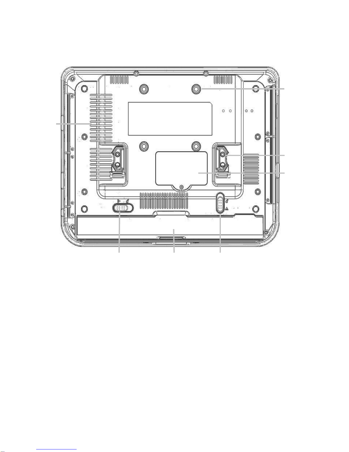
2. System View..................................................................................................7
2.1. Front View...............................................................................................7
2.2. Side View................................................................................................8
2.2.1. Left Side View...............................................................................8
2.2.2. Right Side View ............................................................................8
2.3. Bottom View............................................................................................9
3. Basic Operations .........................................................................................10
3.1. Installing the Hand Strap (option)..........................................................10
3.2. Installing the Kick Stand (option)...........................................................10
3.3. Installing the Battery Pack ....................................................................11
3.4. Connecting the AC Power Adapter .......................................................11
3.5. Turning ON the MT-1200 ......................................................................12
3.6. Suspend Mode......................................................................................12
3.7. Using the Stylus Pen.............................................................................12
4. Drivers Installation .......................................................................................13
4.1. Driver List..............................................................................................13
4.2. Chipset Driver Installation.....................................................................13
4.3. USB Driver Installation..........................................................................15
4.4. VGA Driver Installation..........................................................................18
4.5. Rotation Application Driver Installation..................................................19
4.6. Audio Driver Installation........................................................................21
4.7. Button Driver Installation.......................................................................22
4.7.1. Software Application...................................................................23
4.8. Fujitsu Touch Driver Installation............................................................25
4.9. LAN Driver Installation..........................................................................27
4.10. PCMCIA/SD Card Reader Driver Installation......................................29
4.11. Wireless LAN Driver Installation..........................................................30
5. Replacing Components................................................................................32
5.1. Removing the Battery Pack ..................................................................32
5.2. Replacing the Memory Module.............................................................32
5.3. Replacing the HDD...............................................................................33
6. Specification.................................................................................................34
5

1.Item Checklist
Take out the system unit from the carton. Remove the unit by carefully clutching
the foam inserts and remove slowly to protect the system. The following contents
should be found in the carton:
a. System b. Power Cord
c. Power Adapter d. Stylus Pen
e. Hand Strap (option) and
holders(R&L) f. Kick Stand (Option)
g. Battery Pack h. Driver CD
6

2.System View
Refer to the pictures below to identify the components.
2.1. Front View
1
2
3
4
5
6
NO. Function Remark
1 Wireless LAN Indicator Blue color – Connected to Access Point
Flash – Searching Access Point
2 Charge Indicator Green Color – Battery Mode
Orange color – Charging Battery
Flash – Low Battery
3 Drive Activity Indicator Flash – Access the storage device
4 Windows Task Manager
5 On-Screen Keyboard Defined by software (Refer to Page 26)
6 Screen Rotation Defined by software (Refer to Page 27)
7

2.2. Side View
2.2.1. Left Side View
Lock Port
PCMCIA & SD HDD or CF
2.2.2. Right Side View
Power Switch
LAN
VG
A
USB (2)
Headphone
MIC
Power Input
8

2.3. Bottom View
VESA Holes
Air Vents
Holder
Memory
Compartment
Battery Lock Battery Lock
Battery Pack
9

3.Basic Operations
This section helps you to start using your MT-1200.
3.1. Installing the Hand Strap (option)
a. Place the holders (R&L) in the circled
positions and fasten them with the
screws(2), one on each side .
b. Place the strap rings on the holders on
each side and press toward the direction
as shown by the arrow.
3.2. Installing the Kick Stand (option)
a. Place the strap-stand holders (R&L) in
the circled positions and stabilized with
screws (2), one on each side.
b. Place the Kick Stand in the holders in
the circled positions.
10

3.3. Installing the Battery Pack
a. Insert the battery pack until it clicks into
place. b. Slide both Battery Release tabs to the
lock position.
3.4. Connecting the AC Power Adapter
IMPORTANT! Damage may occur if you use a different adapter to power the
MT-1200 or use the MT-1200’s adapter to power other electrical devices. You
may damage both your battery pack(s) and the MT-1200 with a faulty AC-DC
adapter.
(1) Connect this
end of the power
cord to the AC-DC
converte
r
(3) Insert the
DC power plug
(2) Plug the AC
power cord into an
electrical outlet
11

3.5. Turning ON the MT-1200
a. Press the power button and release at the right side of the system.
3.6. Suspend Mode
The low power modes are designed to save as much electricity as possible by
putting components into a low power consumption mode as often as possible but
also allow full operation on demand. These modes are referred to as “Stand by” or
Suspend-to-RAM and “Hibernation” mode or Suspend-to-Disk (STD).
Recover from suspend mode by pressing the power ON button.
3.7. Using the Stylus Pen
IMPORTANT! DO NOT touch the screen with sharp objects or any other type
of writing instrument. It can damage the screen.
The MT-1200 has a touch-sensitive screen. It allows you to use your stylus pen or finger to
interact with the device. With the MT-1200, you can input data using the full screen area.
12

4.Drivers Installation
4.1. Driver List
Folder/File File Description
<CD>:\K292.htm K292 (MT-1200) Series Driver
List
<CD>:\COMMON\INTEL\Chipset Chipset Driver
<CD>:\COMMON\INTEL\USB20 USB 2.0 Driver
<CD>:\COMMON\INTEL\VGA\i85x VGA Driver
<CD>:\K292\Rotation Rotation Application Driver
<CD>:\COMMON\AC97_Codec\Vinyl Audio Driver
<CD>:\K292\Button_Driver Button Driver
<CD>:\COMMON\Fujitsu_Touch Fujitsu Touch Screen Driver
<CD>:\COMMON\Lan_driver\Intel_PRO_1000 10/100/1000Mb LAN Driver
<CD>:\COMMON\PCMCIA\O2Micro_OZ711Mx PCMCIA/SD Card Reader Driver
<CD>:\COMMON\Wireless_LAN\802.11g\Winb
ond_W89C35 IEEE802.11b/g Wireless LAN
USB Dongle
-The following procedures are for Windows 2000/XP, other platforms are similar.
4.2. Chipset Driver Installation
a. Click the “infinst_enu_6.3.0.1007” on
the My Computer window. b. Click the “Next” button on the Setup
window.
13

c. Click the “Yes” button on the Setup
window. d. Click the “Next” button on the Setup
window.
e. Select “Yes, I want to restart my
computer now” and click the “Finish”
button on the Setup window.
14

4.3. USB Driver Installation
OS Requirements
OS USB 2.0 requirements
Windows
XP USB 2.0 drivers are provided in Service Pack 1 (SP1) for Windows
XP, which is available through Windows Update.
Windows
2000 USB 2.0 drivers are available through Windows Update or Service
Pack 4.
Windows
98SE/Me USB 2.0 drivers are available on the Intel developer site.
Windows
98 (Retail)
Developers and OEMs should contact Orange Ware. For end-users,
if your device does not ship with Windows 98 drivers, contact your
device or system manufacturer. If USB 2.0 drivers are not available,
your device will operate at USB 1.1 speeds
Linux USB 2.0 support is available in kernel 2.4.19 or later development
kernels, or in the 2.4.19 or later production kernel. More information.
a. Right click My Computer on the
desktop and select “properties” b. Select “Hardware”Æ”Device Manager”
on system properties.
15

c. Select ”Other Devices” Æ“Universal Serial Bus (USB) Controller” Æ”Properties” on
Device Manager.
d. Select “Device”Æ“Update Driver…”. e. Click the ”Next” button on the welcome
window.
16

f. Select “Search for a suitable…”and
click the “Next” button on the Install
Hardware Device Drivers window.
g. Select “Specify a location” and click the
“Next” button on the Locate Driver Files
window.
h. Press “Browse” to select driver and
then click the “OK” button to next page. i. Click the “Next” button on Driver Files
Search Results window.
j. Click the “Finish” button to complete
this process. k. Finished.
17

4.4. VGA Driver Installation
a. Click the “Win2K_XP” on the My
Computer window. b. Click the “v14.19.50” on the My
Computer window.
c. Select “win2K_xp141950” on the
v14.19.50 window. d. Click the “Next” button on the Intel(R)
Chipset Graphics Driver Software-
InstallShield(R) Wizard window.
e. Click the “Next” button on the Intel(R)
Graphics Media Accelerator Driver
window.
f. Click the “Yes” button on the Intel(R)
Graphics Media Accelerator Driver
window.
18

g. Select “Yes, I want to restart my
computer now” and click the “Finish”
button on the Intel(R) Graphics Media
Accelerator Driver window.
4.5. Rotation Application Driver Installation
a. Select “Disk 1” on the My Computer
window. b. Select “Setup” on the My Computer
window.
19
Table of contents