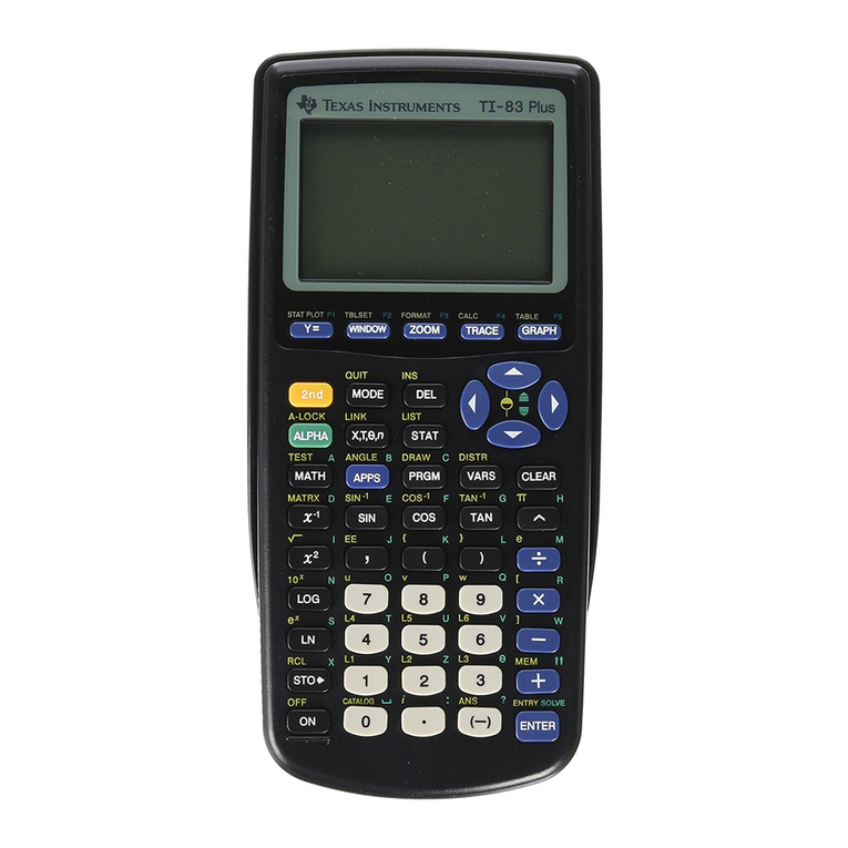
Key Curriculum Press TITANIUM TI-89 User manual

77,,77,,33OOXXVV99RR\\DDJJHH
77KHKH**HHRRPPHHWWHHUUVV66NNHHWWFFKKSSDGDGë
Getting Started
Introductory Tour Customer Support
Advanced Tour
Using the Tools
Selection Arrow Straightedge Tools
Point Tool Text Tool
Compass Tool Custom Tool
Using the Menus
Edit Transform
Display Measure
Construct Graph
Tips and Techniques
Shortcuts Construction Hints
Display Hints Performance Tips
..HH\\&&XXUUUULLFXFXOOXXPP33UUHHVVVVë
Innovators in Mathematics Education
ti

..HH\\&&XXUUUULLFFXXOOXXPP33UUHHVVVVë
Innovators in Mathematics Education
THE
GEOMETER·S
SKETCHPAD®
for TI-89
TI-92 Plus
VoyageTM 200
User Guide and
Reference Manual

The Geometer’s Sketchpad®forTI-89,
TI-92 Plus, andVoyage™ 200 PLT
Version 1.0
Project Design: Nicholas Jackiw
Program Implementation: Keith Dean, Nicholas Jackiw, Scott Steketee
Documentation: Dan Bennett, Steven Chanan, Nicholas Jackiw,
Tom Reich
Special Thanks: Laura Harvey, Zach Teitler, Julio Valella
Product Information: http://www.keypress.com/sketchpad/ti
The Geometer’s Sketchpad is the product of a collaboration between the
Visual Geometry Project at Swarthmore College and Key Curriculum
Press. The Visual Geometry Project was directed by Dr. Eugene Klotz and
Dr. Doris Schattschneider. Portions of this material are based upon work
supported by the National Science Foundation under award DMI-9996103.
Any opinions, findings, and conclusions or recommendations expressed in
this publication are those of the authors and do not necessarily reflect the
views of the National Science Foundation.
The Geometer’s Sketchpad and Dynamic Geometry are registered
trademarks of Key Curriculum Press, Inc. Sketchpad is a trademark of
Key Curriculum Press, Inc. All other brand names and product names are
trademarks or registered trademarks of their respective holders.
Copyright © 2000-2002 by KCP Technologies, Inc. All rights reserved.
KCP Technologies, Inc.
1150 65th Street
Emeryville, CA 94608
The Geometer’s Sketchpad for TI-89,TI-92 Plus, and Voyage™ 200 PLT
is distributed by
Texas Instruments U.S.A.
7800 Banner Drive
Dallas, Texas 75251
TI Support and Service Information
For General Information
E-mail: ti-[email protected]
Phone: 1-800-TI-CARES (1-800-842-2737)
For U.S., Canada, Mexico, Puerto Rico, and Virgin
Islands only
Home Page: education.ti.com
For Technical Questions
Phone: 1-972-917-8324
For Product (hardware) Service
Customers in the U.S., Canada, Mexico, Puerto Rico and Virgin
Islands: Always contact Texas Instruments Customer Support before
returning a product for service.
All other customers: Refer to the leaflet enclosed with this product
(hardware) or contact your local Texas Instruments retailer/distributor.

Contents
Dynamic Geometry®....................................................................................5
Introductory Tour.........................................................................................6
Advanced Tour ..........................................................................................13
Where to Go from Here.............................................................................17
Using Tools................................................................................................22
Selection Arrow Tools...............................................................................24
Point Tool ..................................................................................................27
Compass Tool............................................................................................28
Straightedge Tools.....................................................................................30
Text Tool ...................................................................................................31
Custom Tool ..............................................................................................34
Using Menus..............................................................................................40
ƒEdit Menu ............................................................................................42
„Display Menu.......................................................................................53
…Construct Menu ...................................................................................58
† Transform Menu..................................................................................63
‡ Measure Menu .....................................................................................69
ˆ Graph Menu.........................................................................................74
Shortcuts....................................................................................................81
Construction and Display Hints.................................................................84
Performance Tips.......................................................................................86
88
1 Introducing Sketchpad
2 Tools
3 Commands
4 Tips and Techniques
Index

The Geometer’s Sketchpad®for TI-89, TI-92 Plus, and © 2000-2002 KCP Technologies,Inc.4
Voyage™ 200 PLT User Guide and Reference Manual
Introducing Sketchpad
1
For new users of The Geometer’s Sketchpad forTI-89,TI-92 Plus, and
Voyage™ 200 PLT, this chapter offers a brief introduction to
Sketchpad and Dynamic Geometry. Two tutorials, called Guided
Tours, will give you experience with many of Sketchpad’s features.
The chapter ends with an overview of the rest of this User Guide.
A cube in two-point perspective. While Sketchpad is two-
dimensional in nature, you can use it to build mathematical
models of higher-dimensional geometry “projected” into two
dimensions. This sketch demonstrates a two-point perspective
view of a (three-dimensional) cube. In this perspective, vertical
edges of the 3-D cube remain vertical in its 2-D image, but other
edges recede toward one of two vanishing points on the
image’s horizon line. Dragging the vanishing points alters the
perspective dynamically. (Example from a TI-89.)
The circumcircle of a triangle. This sketch
starts with a triangle ABC. Construct the
midpoints of each side, and then construct
side bisectors—lines perpendicular to each
side passing through that side’s midpoint.
The three bisectors concur in a single
point. This point, the circumcenter of the
triangle, is the center of the unique circle
which passes through all of the triangle’s
vertices. In what sort of situations does a
triangle’s circumcenter fall outside of that
triangle? (Example from a TI-92 Plus.)

The Geometer’s Sketchpad®for TI-89, TI-92 Plus, and © 2000-2002 KCP Technologies,Inc.5
Voyage™ 200 PLT User Guide and Reference Manual
The Geometer’s Sketchpad for TI-89,TI-92 Plus, and Voyage™200 PLT
is a powerful tool for learning concepts from geometry, algebra, and other
math subjects. Geometric relationships can be hard to visualize from the
static, unchanging figures in a text, or even from figures you draw yourself
with traditional tools like a compass, ruler, and protractor. With Sketchpad,
you can construct and measure figures easily and more precisely than with
traditional tools. But more importantly, Sketchpad’s Dynamic Geometry
lets you move parts of your constructions to see which properties change
and which don’t. With Dynamic Geometry at your fingertips you can put
the problems and theorems you encounter in your math class in motion,
revealing relationships and giving you a whole new way of seeing
mathematics.
Try the following two Guided Tours for an overview of Dynamic
Geometry and how to use Sketchpad on your TI-89 or TI-92 Plus
/Voyage 200 PLT. Or explore on your own, and turn to the reference
sections if you need help learning how to do something.
This manual assumes that Sketchpad has already been installed as a Flash
application on your handheld device. Detailed Flash application
installation instructions are available from education.ti.com/guides.
Dynamic Geometry®
This section gives a brief introduction to The Geometer’s
Sketchpad and to the significance of Dynamic Geometry.
Installing Sketchpad

The Geometer’s Sketchpad®for TI-89, TI-92 Plus, and © 2000-2002 KCP Technologies,Inc.6
Voyage™ 200 PLT User Guide and Reference Manual
With Sketchpad’s drawing tools and menus, you can construct figures that
are very flexible, so that you can drag any parts of them wherever and
however you want; or you can construct them with properties that limit
how you can change them. In this tour, you’ll draw a triangle that can be
any size or shape. Then you’ll construct an isosceles triangle, which is
constrained so that two sides are always equal. You’ll also discover some
other properties of isosceles triangles. In the process, you’ll learn some of
the basics of using Sketchpad’s drawing tools, as well as the ƒEdit,
„Display, …Construct, and ‡Measure menus.
Follow the steps below to construct a general triangle.
Steps
Display
1. Press Oand select [The
Geometer’s] Sketchpad to open
Sketchpad. You’ll see a blank
Sketchpad sketch, with
Sketchpad’s menus (ƒ–ˆ)
along the top of the screen and
the toolbox (Š) along the right
edge.
2. Press Š(TI-89: 2 Š) to
enter the toolbox. Then press @
until the Segment tool blinks.
(The Segment tool appears at
the left of three pop-up
Straightedge tools.) Press ¸
to choose it. Once the Segment
tool is active, the cursor
becomes a cross-hair.
3. Press ¸to construct a
segment endpoint. Press @to
move away from the first
endpoint, constructing a
segment as you move. Press
¸again to construct the
segment’s second endpoint.
4. Construct the first of two more segments to complete the triangle.
With the cursor still positioned on the endpoint of your first segment,
construct a second segment by pressing ¸, @to drag away, and
¸again to complete the second segment.
Introductory Tour
This is the first of two Guided Tours, which are geometric
investigations with step-by-step instructions designed to
introduce you to many of Sketchpad’s features.
Drawing
The square brackets in the
instructions at right mean
that text this appears as
Sketchpad on the TI-89
and as The Geometer’s
Sketchpad on the
TI-92 Plus/Voyage™ 200
PLT.
The @symbol refers to the
large multidirectional cursor
pad on the TI-92 Plus and to
the four cursor keys on the
TI-89.
The Straightedge tools are
used for making segments,
rays, and lines. When you
choose one, it remains
active until you choose a
different tool or arrow.
On the TI-89,you can use
Minstead of ¸ for
easier keyboard entry when
using tools or selecting
objects.

The Geometer’s Sketchpad®for TI-89, TI-92 Plus, and © 2000-2002 KCP Technologies,Inc.7
Voyage™ 200 PLT User Guide and Reference Manual
5. With the cursor still positioned
on the endpoint of your second
segment, press ¸, @back
to the original endpoint, and
¸to construct the third
segment. Be sure this segment
connects back to the starting
point before you press the final
¸that completes the
triangle.
You can drag parts of your triangle to change its size and shape.
Steps
Display
1. Press Nto quit the Segment
tool and choose the Arrow tool.
2. Position the Arrow over a
vertex. (The cursor changes to a
sideways arrow when it points
to an object.) Press and hold ‚
(TI-89: j), then press @to
drag the vertex. Drag it around
the entire screen.
3. Practice dragging the other
vertices of the triangle. Try
dragging a side, too. Notice how
you can make this triangle any
size or shape.
Dragging is at the heart of Dynamic Geometry. It lets you generalize from
a single construction. For example, in the steps above, you drew a single
triangle. But by dragging, you can look at many possible sizes and shapes
for a triangle. You can also drag to check that your construction is holding
together properly—that all possible appearances are still triangles. Drag
often!
Sketchpad’s unlimited undo lets you look back at a previous state of your
sketch. You can also use undo if you need to correct a construction
mistake.
Steps
Display
1. Press ƒEdit: ¨Undo to
undo the last step. Repeat to
undo a few more steps.
The Edit menu (TI-92 Plus
/Voyage™ 200 PLT)
2. Press ƒEdit: ©Redo to redo the steps you’ve just undone.
Throughout these tours, use undo (and redo) to revisit your work, or
to correct any mistakes you make while constructing objects.
You might notice a
“snapping” action when the
cursor gets close to an
existing point.
Dragging
Nserves many purposes
in Sketchpad—one of which
is a shortcut for the Arrow
tool. (You can also choose
the Arrow by pressing
[TI-89: 2]Š.)
Undoing
Every menu has a name,
represented by an icon on
the screen. The ƒmenu is
the Edit menu.

The Geometer’s Sketchpad®for TI-89, TI-92 Plus, and © 2000-2002 KCP Technologies,Inc.8
Voyage™ 200 PLT User Guide and Reference Manual
You can save your work in case you want to return to it later, after you’ve
worked on something else.
Steps
Display
1. Press ƒEdit: oSketch:
ªSave to save the sketch.
Sketchpad presents a dialog box
that lets you specify a folder and
a variable name.
2. To save this sketch in the main
folder, press Dto move the
cursor into the Variable field
and type triang1. Then press
¸twice to save.
Congratulations! You’ve constructed your first geometric figure with
Sketchpad: a triangle.
In this part of the investigation, you’ll construct an isosceles triangle and
investigate some of its properties.
Steps
Display
1. Press ƒEdit: oSketch:
¨New to open a new sketch.
The sketch area becomes blank
again.
2. Press Š(TI-89: 2 Š), Dto
the Segment tool, and press
¸to choose the Segment
tool. Then press ¸@
¸to construct a segment.
3. Press Š(TI-89: 2 Š) D
until the Compass tool blinks,
then press ¸to choose it.
4. To construct a circle with this
segment as radius, move the
Compass tool’s cursor to one
segment endpoint, press ¸.
Then press @to start drawing a
circle. Position the cursor over
the second segment endpoint
and press ¸to finish your
circle there.
Saving
Constructing
A shortcut for activating the
segment tool is ¥†
(TI-89 : ¥y). (There are
comparable shortcuts for
each of the other tools in the
Toolbox based on position.
For example, the Point tool
is the second tool down, so
its shortcut is ¥„
[TI-89: ¥©].)
This is tricky! Be sure you
start your circle on one
segment endpoint and finish
it with the cursor directly
over the second segment
endpoint. Otherwise, the
circle and segment will not
be connected. Look for the
snapping action when the
cursor gets close to the
point you want.

The Geometer’s Sketchpad®for TI-89, TI-92 Plus, and © 2000-2002 KCP Technologies,Inc.9
Voyage™ 200 PLT User Guide and Reference Manual
5. Press Nto return to the
Arrow, then press and hold ‚
(TI-89:j) while using @to
drag the circle’s two defining
points to be sure the circle and
segment are connected.
6. Use the Segment tool to draw
another radius of the circle. Be
sure to place one endpoint with
the cursor positioned at the
circle’s center (¸) and the
other endpoint with the cursor
anywhere on the circle’s
circumference (¸).
7. Construct a segment to connect
the two points on the circle and
complete the triangle.
8. Press Nto return to the
Arrow. Then position it on a
vertex, press and hold ‚
(TI-89 : j), and press @to
drag the vertex. Drag the other
vertices too, and observe how
each changes the triangle.
Did you notice that two sides of this triangle always appear to stay equal?
Why? Did you notice that dragging one of the vertices didn’t change the
length of these equal sides? What’s different about that point?
You can automate dragging using animation. Follow these steps to animate
one vertex traveling around the circle.
Steps
Display
1. Press Nto deselect all
objects. Press ¸on the
point on the circle that does not
change the circle’s radius to
select it. If you’re not sure you
have the right point, drag it first.
2. Press „Display: nAnimate
Point.
3. To stop the animation, Press „Display: (TI-89: j) ÑStop
Animation.
There should be only two
points in your sketch that
define both the segment and
the circle. If the circle
separates from the segment
when you drag, undo (ƒ
¨)until the circle is gone
and try again.
Remember: On the TI-89,
you can use Mas a
shortcut for ¸when
drawing or selecting objects.
(The Mkey might be
easier to reach.)
Animating
You’ve probably noticed that
pressing ¸with the
Arrow over an object
changes the object’s
appearance to indicate
you’ve selected it. In
general, you need to select
objects that you want to act
upon with menu commands.

The Geometer’s Sketchpad®for TI-89, TI-92 Plus, and © 2000-2002 KCP Technologies,Inc.10
Voyage™ 200 PLT User Guide and Reference Manual
You can hide parts of your construction to change its appearance without
affecting its geometric properties.
Steps
Display
1. Press Nto deselect all
objects. Then press ¸on
the circle to select it. Press
„Display: ¨Hide [Circle].
The circle disappears.
2. Drag vertices of the triangle.
Notice that even when hidden,
the circle determines the
behavior of your triangle (it
stays isosceles).
You constructed the isosceles triangle using only Sketchpad’s Compass
and Straightedge tools. You can create almost any Euclidean construction
using just these tools, but the Construct menu offers shortcuts for many
constructions.
Steps
Display
1. Construct the midpoint of the
base of the triangle. To do this,
first deselect all objects (N),
then select the base. (Press
¸on the side that’s not
necessarily equal to another
side). Then press
…Construct: ©Midpoint.
2. In order to construct a perpendicular line through this midpoint,
you’ll have to select two objects—a point to go through (the
midpoint, in this case), and a straight object to be perpendicular to
(the base segment, in this case). The just-constructed midpoint is
already selected. Select the base segment as well, by moving the
Arrow to it and pressing ¸.
3. Construct the perpendicular line
defined by your selections by
choosing …Construct:
nPerpendicular Line.
Sketchpad constructs and
displays the line perpendicular
to the selected segment, passing
through the selected midpoint.
In this case, because it passes through the segment’s midpoint, your
perpendicular line is a perpendicular bisector. What do you notice about
the perpendicular bisector of the base of an isosceles triangle? Is this true
for any isosceles triangle?
Hiding
Constructing with
the …Construct
Menu
If the Midpoint command in
the …menu has a padlock
icon (Œ) next to it, it’s not
available because the
selection is not correct.
Press Nto deselect all
objects and try again.

The Geometer’s Sketchpad®for TI-89, TI-92 Plus, and © 2000-2002 KCP Technologies,Inc.11
Voyage™ 200 PLT User Guide and Reference Manual
Dynamic Geometry’s real power lies in how it enables you to make
generalizations about figures you construct and manipulate.
Steps
Display
1. Drag different vertices of the
triangle and observe the
perpendicular bisector.
By observing the perpendicular bisector in your isosceles triangle as you
change the triangle’s size and shape you can conjecture (make an educated
guess) that the perpendicular bisector of the base of any isosceles triangle
passes through the opposite vertex.
Making measurements and observing them while you drag a figure is
another way to arrive at geometric conjectures. In this part of the tour,
you’ll measure the angles in your triangle.
Steps
Display
1. Press Nto deselect all
objects, then press ¸on
each of the three vertices of
your triangle to select them. Pay
attention to the order in which
you select them. The second
(middle) point you select will be
the vertex of the angle you’re
about to measure.
2. Press ‡ Measure: zAngle to
measure the angle.
3. Press Nto deselect all, then select the three vertices of the triangle
again, with your second selection a different point than the second
selection you made in step 1.
4. Press ‡ Measure: zAngle to measure this second angle.
5. Press Nto deselect all, then select the points that define the third
angle in your triangle, choosing a second selection different from the
second selections you made in steps 1 and 3.
6. Press ‡ Measure: zAngle to
measure this third angle.
What do you notice about the three angle measures? Confirm that the two
equal measurements are really measures of different angles. (Check that
their vertices—the points in the middle of the names displayed in their
measures—are different.)
Conjecturing
Measuring
Just as you use three points
to name an angle—such as
angle ABC—in Sketchpad
you select three points to
measure an angle.
Sketchpad names the
measurement using the
labels of the points that
define the angle. You’ll learn
how to show or change
these labels in the next
chapter.

The Geometer’s Sketchpad®for TI-89, TI-92 Plus, and © 2000-2002 KCP Technologies,Inc.12
Voyage™ 200 PLT User Guide and Reference Manual
Drag different parts of the figure to verify that the base angles of an
isosceles triangle always appear to be congruent.
There are various ways to change how things are displayed in a sketch—
and even to change geometric relationships—besides undoing and hiding.
In this part of the tour, you’ll learn how to show hidden objects and how to
split related objects apart.
Steps
Display
1. Press „Display: ©Show All
Hidden. The circle you hid
earlier should reappear.
2. Drag each of the two points on
the circle and observe the
perpendicular bisector of the
chord between them. Also
observe which of the two points
does not change the circle’s
radius.
3. Animate the point that does not
change the circle’s radius.
(Select it and Press „Display:
nAnimate Point.) Observe the
chord—the triangle’s base
segment—and its perpendicular
bisector as this point travels
around the circle.
4. To stop the animation, Press „Display: Ñ Stop Animation
(TI-89: j A).
5. While the point on the circle is
selected, Press ƒEdit:
ySplit Point From Circle
(Split From Object on the
TI-89). The point is redefined to
be no longer on the circle.
6. Drag the point to confirm that it’s no longer related to the circle.
Now that the point is no longer on the circle, what kind of triangle do you
have? Do the conjectures you made about the perpendicular bisector of the
base of an isosceles triangle (or of a chord in a circle) and about the base
angles of an isosceles triangle still hold for this triangle?
If you wish to “repair” your isosceles triangle, select the point that you
split from the circle, and select the circle itself. Then press ƒEdit:
yMerge Point To Circle (Merge to Path on the TI-89) to redefine the
point on the circle.
With this relatively simple construction of an isosceles triangle, you
sampled many of Sketchpad’s features and commands and developed a
sense of the power and significance of Dynamic Geometry for making
conjectures. The next tour takes you to two menus you haven’t seen yet:
the †Transform menu and the ˆGraph menu.
Modifying a Sketch
Summary

The Geometer’s Sketchpad®for TI-89, TI-92 Plus, and © 2000-2002 KCP Technologies,Inc.13
Voyage™ 200 PLT User Guide and Reference Manual
Sketchpad’s †Transform menu lets you translate (slide), rotate (turn),
dilate (shrink or stretch), or reflect (flip). In this part of the tour, you’ll use
a reflection to construct an isosceles triangle.
Steps
Display
1. Start Sketchpad, or, if it’s started already, press ƒEdit: oSketch:
¨New to open a new sketch.
2. Press Š(TI-89: 2 Š) @
until the Line tool (as opposed
to the Segment or Ray tool)
blinks, then press ¸to
activate it.
3. Press ¸@¸to draw
a vertical line.
4. With the line still selected, Press † Transform: ©Mark Mirror
to mark the line as the mirror across which you’ll reflect objects.
Sketchpad confirms this mark with a brief animation.
5. Choose the Point tool from the
toolbox: Š(TI-89: 2 Š)
@ ¸.
6. Move the cursor to one side of
the line and press ¸to
construct a point nearby.
7. With the point still selected,
Press †Transform:
ÑReflect (TI-89: j A).
Sketchpad constructs and
displays the image of your point
reflected across the marked
mirror.
8. Press Nto return to the Arrow, then drag either point to see how
its mirror image behaves. Try dragging the mirror and the points
defining it too.
Advanced Tour
In the previous introductory tour, you learned how to construct
an isosceles triangle using a Euclidean (compass and
straightedge) approach. In this section, you’ll use
transformations to construct another isosceles triangle. Then
you’ll investigate your triangle on a coordinate grid.
Transformational
Approaches
Reminder: A shortcut for
activating the segment tool
is ¥† (TI-89: ¥y).
Repeat the shortcut to scroll
through the palette of
straightedge tools.
Reminder: On the TI-89,
Mis a shortcut for
¸when using tools and
selecting objects.

The Geometer’s Sketchpad®for TI-89, TI-92 Plus, and © 2000-2002 KCP Technologies,Inc.14
Voyage™ 200 PLT User Guide and Reference Manual
9. Press Nto deselect all. Press
¸on three points: the two
points not on the line and one of
the points that defines the line.
10. Press …Construct:
ySegments to construct
segments connecting the points
you selected.
11. Drag some more. What kind of triangle do you have? Notice that it’s
controlled by any of four points. One of the points is not on the
triangle, but it controls the mirror line.
In this part of the tour, you’ll analyze your triangle on a coordinate grid.
Steps
Display
1. Press Nto deselect all objects.
2. Press ˆ Graph:
(TI-89:2 ˆ)
ªGraph Form:
©Square Grid. Sketchpad
displays a coordinate system
(two axes and a grid).
3. The coordinate system is
defined by its origin and a unit
point to the right of the origin.
To shrink the axes’ scales, press
Nto deselect all, then drag
the unit point toward the origin.
Drag it just until you can see the
5 on the x-axis.
4. Press Nto deselect all, then
press ¸on each of the three
triangle vertices. Press
‡Measure: Analytic:
(TI-89: jD)
Ú¨ Coordinates.
5. Press Nto deselect all, then
press ¸on the mirror line.
Press ‡ Measure: Analytic:
(TI-89: j D)©Equation.
6. Press ˆ Graph: (TI-89: 2 ˆ) zSnap To Grid.
7. Drag the points that control the mirror line. Observe how they snap to
the grid.
8. Drag the triangle’s base vertices.
Observe their coordinates as one
or both of them snap to the grid.
Notice that one point will have
whole-number coordinates,
while the mirror-image point
may not, depending on the angle
of the mirror line.
Analytic
Approaches
The unit point of a
coordinate system appears
beside the origin, and
determines the magnitude of
that coordinate system’s
units. In a square coordinate
system, the unit point
appears on the horizontal
axis at (1, 0).

The Geometer’s Sketchpad®for TI-89, TI-92 Plus, and © 2000-2002 KCP Technologies,Inc.15
Voyage™ 200 PLT User Guide and Reference Manual
Next, you’ll make some conjectures about the coordinates of the vertices of
your isosceles triangle when it’s located in different ways on the
coordinate grid. You’ll also try to solve some challenges about the sketch.
1. Drag the mirror line’s control points so that they lie on the y-axis.
Drag the triangle base vertices around and observe the coordinates. If
a point has coordinates (a, b), what are the coordinates of its mirror
image across the y-axis?
2. Locate the mirror line on the x-axis. Drag the triangle base vertices
around and observe the coordinates. If a point has coordinates (a, b),
what are the coordinates of its mirror image across the x-axis?
3. Drag the mirror line’s control points so that the line’s equation is
y=x. Drag the triangle base vertices around and observe the
coordinates. If a point has coordinates (a, b), what are the coordinates
of its mirror image across the line y= x?
4. See if you can locate the three vertices of the triangle so that each one
has 0 as one of its coordinates. Describe where you located the points.
5. See if you can locate the three vertices of the triangle so that one
vertex is at the origin and each of the two other vertices has 0 as one
of its coordinates. Describe where you located the points and describe
the triangle.
6. Locate the mirror line so that its equation is y= 2x. See if you can
locate the base vertices so that they both lie on the grid—that is, so
that they both have whole-number coordinates. Describe how you did
this. (Hint: You might find this easier if you construct the midpoint of
the base first.)
In this tour and the previous introductory tour, you’ve seen two approaches
to constructing and investigating an isosceles triangle. In the introductory
tour you took a Euclidean approach to the construction, using the drawing
tools and the Construct menu. In this tour you took a Transformational
approach, using a reflection in your construction. You also analyzed your
figure in this tour using a coordinate system. In the process, you were
introduced to the power of Dynamic Geometry as well as all of
Sketchpad’s menus and most of its tools. You may also have discovered
something new about geometry!
The answers to Conjectures and Challenges follow.
1. (–a, b)
2. (a, –b)
Conjectures and
Challenges
Summary

The Geometer’s Sketchpad®for TI-89, TI-92 Plus, and © 2000-2002 KCP Technologies,Inc.16
Voyage™ 200 PLT User Guide and Reference Manual
3. (b, a)
4. Each point must lie on an axis.
If the vertex opposite the base is
on the y-axis, the two base
vertices must be on the x-axis.
5. The vertex opposite the base
must be at the origin, with each
base vertex on an axis. The
triangle is a right isosceles
triangle.
6. This is tough! The midpoint of
the base is the point where the
base intersects the mirror line.
The base vertices will both be
grid points if and only if this
midpoint is a grid point. So,
locate a point on the grid that
the mirror line passes through,
such as (0, 0), (1, 2), (2, 4), and
so on. Try to position a base
vertex so that the midpoint of
the base lands on one of these
points. You can use the fact that
the slope of the base is –1/2.

The Geometer’s Sketchpad®for TI-89, TI-92 Plus, and © 2000-2002 KCP Technologies,Inc.17
Voyage™ 200 PLT User Guide and Reference Manual
To start Sketchpad, turn on your TI-89 or TI-92 Plus/Voyage™200 PLT,
press Oand select[The Geometer’s] Sketchpad. You’ll see a blank
Sketchpad sketch, with Sketchpad’s menus (ƒ–ˆ) along the top of the
screen and the toolbox (Š) along the right edge.
Edit
Display
Construct
Transform
Measure
Graph
Selection Arrow Tool
Point Tool
Compass Tool
Straightedge Tool
Text Tool
Custom Tool
The Sketch Window (TI-92 Plus/Voyage 200 PLT)
You’ll use the Point, Compass, and Straightedge tools to draw objects in
the construction area. You’ll use the Arrow to select and drag objects and
the Text tool to label objects and add text to your sketch. The Custom tool
lets you make and use tools of your own. You’ll use the menus to choose
various commands for acting on your sketch and objects in your sketch.
See the Tools chapter for more detail about tools.
Choosing a Tool
Press Š(TI-89: 2 Š) to enter the toolbox.
Use the @cursor controls to highlight the tool you wish to use.
Press ¸to choose a highlighted tool.
Alternately, use the keyboard shortcuts ¥ƒ–¥ˆ (TI-89: ¥¨–¥{)
to activate tools directly. The number of the shortcut corresponds with the
position of the tool—for example, the Compass tool, which is the third tool
down, can be activated using ¥… (TI-89: ¥ª). For a palette of tools
(the Arrow and Straightedge tools), type the shortcut repeatedly to scroll
through the palette.
Where to Go from Here
If you successfully completed the Guided Tours, you’ve made
a good start at learning how to use Sketchpad. At this point,
you may choose to explore Sketchpad more on your own,
referring back to this documentation as you need it, or you
may prefer to read on to learn more about the software’s many
features. This section gives a brief overview of what you’ll find
in Sketchpad and previews the other sections of the
documentation so that you can more easily find the specific
information you’re looking for.
The Sketch
Tools

The Geometer’s Sketchpad®for TI-89, TI-92 Plus, and © 2000-2002 KCP Technologies,Inc.18
Voyage™ 200 PLT User Guide and Reference Manual
Drawing
Once a drawing tool—the Point, Compass, Straightedge, or Custom tool—
is chosen, use the @cursor controls to move to the location where you
wish to start drawing an object. This can be a blank area, an existing point,
or on an existing object.
Press ¸to construct a point. (On the TI-89, you may use Mas a
shortcut for ¸.)
For objects defined by two points—segments, rays, lines, and circles—use
@to move to the location where you wish to finish constructing the
object, and press ¸to construct the second point.
The chosen tool remains active until you choose a different tool.
Dragging
Choose the Arrow tool. You can do this by entering the toolbox Š,
(TI-89: 2 Š) highlighting the Arrow, and pressing ¸, or you can
simply press Nto quit the current tool and choose the Arrow.
Use @to position the cursor over the object you wish to drag. When it’s
over an object, the cursor will turn into a horizontal arrow.
Press and hold down ‚(TI-89: j) as you move the object with @.
See the Commands section for more details about using menu commands.
Sketchpad’s six menus are ƒEdit,„Display,…Construct,
†Transform,‡ Measure, and ˆ Graph.
Selecting
To act on objects using menu commands, you’ll need to select them:
1. Choose the Arrow tool.
2. Using the @cursor controls, position the cursor over an object.
When it’s over an object, the cursor will turn into a horizontal arrow.
3. Press ¸. Sketchpad selects the object. Select additional objects
by repeating steps 2 and 3.
Selected objects appear thickened. Previously selected objects will remain
selected as long as you’re selecting objects. Many menu commands depend
on multiple selections. If you press ¸with the cursor in a blank area,
everything will become deselected. You can also press Nto deselect
everything.
Choosing Commands
To open a menu, press its assigned function key. To choose a menu item,
press its assigned number or letter, or highlight it using the cursor controls
and press ¸.
Commands
Again, on the TI-89, M
may be used as an
alternative to ¸when
drawing or selecting objects.

The Geometer’s Sketchpad®for TI-89, TI-92 Plus, and © 2000-2002 KCP Technologies,Inc.19
Voyage™ 200 PLT User Guide and Reference Manual
The ƒEdit Menu
The ƒEdit menu (TI-92 Plus/Voyage™ 200 PLT)
These commands allow you
to modify your sketch in
various ways. Use the o
Sketch submenu to open a
new sketch, open a
previously saved sketch, or
save the current sketch. The
nProperties and
ÑPreferences
(TI-89: j A) commands
contain many powerful
options for tailoring
individual objects and
general program operations
to your needs.
The „Display Menu
The „Display menu (TI-89)
Use these commands to hide
and show objects and their
labels, to trace objects, and
to animate objects.
The …Construct Menu
The …Construct menu (TI-92 Plus
/Voyage 200 PLT)
This menu provides a large
assortment of Euclidean
constructions, as well as interiors
and loci. Some of these commands
construct the same objects as
some of the tools. Others are
shortcuts for commonly
performed constructions that
could be done with the tools but
would be more time-consuming
that way. Each command depends
on particular selections in your
sketch in order to be available.
Unavailable commands appear
with a padlock icon next to them.
On the TI-89, command Ais
called “Circle thru Point” and
command Bis called “Circle
by Radius.”
This manual suits for next models
2
Table of contents
Popular Software manuals by other brands

Aruba Networks
Aruba Networks PowerConnect W Clearpass 100 Software manual

Netscape
Netscape NETSCAPE MANAGEMENT SYSTEM 4.5 Installation and setup guide

HyperSynth
HyperSynth HyperSID user manual

Red Hat
Red Hat ENTERPRISE LINUX 3 - SECURITY GUIDE System administration guide

Autodesk
Autodesk LUSTRE 2011 brochure

Novell
Novell GROUPEWISE 8 - SUPPORT PACK 2 05-2010 manual