Klutch 144348 User manual

Compact Right
Angle Drill
INSTRUCTION MANUAL
Item # 144348
WARNING:
Read carefully and understand all INSTRUCTIONS before
operating. Failure to follow the safety rules and other basic
safety precautions may result in serious personal injury.

Thank you very much for choosing a NORTHERN TOOL + EQUIPMENT CO., INC.
Product! For future reference, please complete the owner's record below:
Model: _______________ Purchase Date: _______________
Save the receipt, warranty and these instructions. It is important that you read the
entire manual to become familiar with this product before you begin using it.
This machine is designed for certain applications only. Northern Tool + Equipment
cannot be responsible for issues arising from modification. We strongly recommend
this machine is not modified and/or used for any application other than that for
which it was designed. If you have any questions relative to a particular application,
DO NOT use the machine until you have first contacted Northern Tool + Equipment
to determine if it can or should be performed on the product.
For technical questions please call 1-800-222-5381.
INTENDED USE
This Compact Right Angel Drill is designed for drilling between studs and joints.
TECHNICAL SPECIFICATIONS
snoitacificepSnoitpircseD
Voltage/Frequeney: 120V / 60Hz
Power: 8 Amp
Rated running speed: 340 and 1375 RPM
Chuck size capacity: 1/8in. to 1/2in. Shank Diameter Drill Bits
GENERAL SAFETY RULES
WARNING! Read and understand all instructions. Failure to follow all instructions listed
below may result in electric shock, fire and/or serious injury.
WARNING! The warnings, cautions, and instructions discussed in this instruction
manual cannot cover all possible conditions or situations that could occur. It must be
understood by the operator that common sense and caution are factors which cannot
be built into this product, but must be supplied by the operator.
SAVE THESE INSTRUCTIONS
WORK AREA
• Keep your work area clean and well lit. Cluttered and dark work areas invite accidents.
• Do not operate power tools in explosive atmospheres, such as in the presence of
flammable liquids, gases, or dust. Power tools create sparks which may ignite the dust
or fumes.
1
UNPACKING
When unpacking, please check if any parts are missing or broken, please call Northern Tool
Description Qty
Angel drill . . . . . . . . . . . . . . . . . . . .1
Side handle . . . . . . . . . . . . . . . . . .1
Spare carbon brush set . . . . . . . ...1
Instruction manual . . . . . . . . . . . . .1

2
• Keep bystanders, children, and visitors away while operating a power tool.
Distractions can cause you to lose control.
ELECTRICAL SAFETY
WARNING! Always check to ensure the power supply corresponds to the voltage on the
rating plate.
• Grounded tools must be plugged into an outlet properly installed and grounded in
accordance with all codes and ordinances. Never remove the grounding prong or
modify the plug in any way. Do not use any adapter plugs. Check with a qualified
electrician if you are in doubt as to whether the outlet is properly grounded. If the
tools should electrically malfunction or break down, grounding provides a low resistance
path to carry electricity away from the user.
• Avoid body contact with grounded surfaces such as pipes, radiators, ranges, and
refrigerators. There is an increased risk of electric shock if your body is grounded.
• Do not expose power tools to rain or wet conditions. Water entering a power tool will
increase the risk of electric shock.
• Do not abuse the power cord. Never use the power cord to carry the tools or pull
the plug from an outlet. Keep the power cord away from heat, oil, sharp edges or
moving parts. Replace damaged power cords immediately. Damaged power cords
increase the risk of electric shock.
• When operating a power tool outside, use an outdoor extension cord marked “W-A”
or “W.” These cords are rated for outdoor use and reduce the risk of electric shock.
• Do not expose power tools to rain or wet conditions. Water entering a power tool will
increase the risk of electric shock.
• Do not let your fingers touch the terminals of plug when installing or removing from
the outlet.
• Ground fault circuit interrupters. If work area is not equipped with a permanently
installed Ground Fault Circuit Interrupter outlet (GFCI), use a plug-in GFCI between power
tool or extension cord and power receptacle.
PERSONAL SAFETY
• Stay alert. Watch what you are doing and use common sense when operating a power
tool. Do not use a power tool while you are tired or under the influence of drugs, alcohol or
medication. A moment of inattention while operating power tools may result in serious
personal injury.
• Dress properly. Do not wear loose clothing, dangling objects, or jewelry. Keep your hair,
clothing and gloves away from moving parts. Loose clothes, jewelry or long hair can be
caught in moving parts. Air vents often cover moving parts and should be avoided.
• Avoid accidental starting. Be sure the power switch is off before plugging in.
Carrying power tools with your finger on the power switch, or plugging in power tools with
the power switch on, invites accidents.
• Remove adjusting keys or wrenches before turning the power tool on. A wrench or a
key that is left attached to a rotating part of the power tool may result in personal injury.

• Do not overreach. Keep proper footing and balance at all times. Proper footing and
balance enables better control of the power tool in unexpected situations.
• Use safety equipment. Always wear eye protection. Nonskid safety shoes, hard hat, or
hearing protection must be used for appropriate conditions. Always wear ANSI-approved
safety impact goggles and thick rubber boots during use and maintenance.
TOOL USE AND CARE
• Use clamps (not included) or other practical ways to secure and support a smaller
workpiece to a stable platform. Holding the work by hand or against your body is unsta-
ble and may lead to loss of control.
• Do not force the tool. Use the correct tool for your application. The correct tool will do
the job better and safer at the rate for which it is designed.
• Do not use the power tool if the power switch does not turn it on or off. Any tool that
cannot be controlled with the power switch is dangerous and must be replaced.
• Disconnect the power cord plug from the power source before making any adjust-
ments, changing accessories, or storing the tool. Such preventive safety measures
reduce the risk of starting the tool accidentally.
• Store idle tools out of reach of children and other untrained persons. Tools are dan-
gerous in the hands of untrained users.
• Maintain tools with care. Keep tools clean. Properly maintained tools are easier to con-
trol. Do not use a damaged tool. Tag damaged tools “Do not use” until repaired.
• Check for misalignment or binding of moving parts, breakage of parts, and any
other condition that may affect the tool’s operation. If damaged, have the tool serv-
iced before using. Many accidents are caused by poorly maintained tools.
• Use only accessories that are recommended by the manufacturer for your model.
Accessories that may be suitable for one tool may become hazardous when used on
another tool.
SERVICE
• Tool service must be performed only by qualified repair personnel. Service or mainte-
nance performed by unqualified personnel could result in a risk of injury.
• When servicing a tool, use only identical replacement parts. Follow instructions in
the “Maintenance” section of this manual. Use of unauthorized parts or failure to follow
maintenance instructions may create a risk of electric shockor injury.
3

GROUNDING
WARNING! Improperly connecting the grounding wire can result in the risk of elec-
tric shock. Check with a qualified electrician if you are in doubt as to whether the out-
let is properly grounded. Do not modify the power cord plug provided with the tool.
Never remove the grounding prong from the plug. Do not use the tool if the power cord
or plug is damaged. If damaged, have it repaired by a service facility before use. If the
plug will not fit the outlet, have a proper outlet installed by a qualified electrician.
GROUNDED TOOLS: TOOLS WITH THREE-PRONG PLUGS
1. Tools marked with “Grounding
Required” have a three-wire cord
and three-prong grounding plug.
The plug must be connected to a
properly grounded outlet. If the tool
should electrically malfunction or
break down, grounding provides a
low resistance path to carry electricity
away from the user, reducing the
risk of electric shock. (See Fig. A)
2. The grounding prong in the plug is
connected through the green wire inside the cord to the grounding system in the tool. The
green wire in the cord must be the only wire connected to the tool’s grounding system
and must never be attached to an electrically “live” terminal. (See Fig. A)
3. Your tool must be plugged into an appropriate outlet, properly installed and grounded in
accordance with all codes and ordinances. The plug and outlet should look like that in the
following illustration. (See Fig. A)
EXTENSION CORDS
1. Grounded tools require a three-wire extension cord.
2. As the distance from the supply outlet increases, you must use a heavier gauge exten-
sion cord. Using extension cords with inadequately sized wire causes a serious drop in
voltage, resulting in loss of power and possible tool damage. (See Fig. B next page)
3. The smaller the gauge number of the wire, the greater the capacity of the cord. For
example, a 14 gauge cord can carry a higher current than a 16 gauge cord. (See Fig. B.)
4. When using more than one extension cord to make up the total length, make sure each
cord contains at least the minimum wire size required. (See Fig. B.)
5. If you are using one extension cord for more than one tool, add the nameplate amperes
and use the sum to determine the required minimum cord size. (See Fig. B.)
6. If you are using an extension cord outdoors, make sure it is marked with the suffix “W-A”
(“W” in Canada) to indicate it is acceptable for outdoor use.
7. Make sure your extension cord is properly wired and in good electrical condition. Always
replace a damaged extension cord or have it repaired by a qualified electrician before
using it. Protect your extension cords from sharp objects, excessive heat, and damp or
wet areas.
FIGURE A
3-Prong Plug
Electrical
Outlet

SPECIFIC SAFETY RULES
1. Maintain a safe working environment. Keep the work area well lit. Make sure there is
adequate surrounding workspace. Always keep the work area free of obstructions,
grease, oil, trash, and other debris. Do not use the Drill in areas near flammable
chemicals, dusts, and vapors.
2. Maintain labels and nameplates on the Drill. These carry important information. If unreadable
or missing, contact Northern Toolfor a replacement.
3. Use the right product for the right job. There are certain applications for which this
product was designed. Do not use small equipment, tools, or attachments to do the work
of larger industrial equipment, tools, or attachments. Do not use this product for a
purpose for which it was not intended.
4. Wear ANSI-approved safety impact eye goggles underneath an approved safety impact
full face shield. Also use approved hearing protection and heavy-duty work gloves. If
necessary, wear an approved dust mask or respirator.
5. Industrial applications must follow OSHA requirements.
6. When using the drill, always maintain a firm grip on the tool with both hands.
7. Do not handle the drill with wet hands.
8. Avoid unintentional starting. Make sure you are prepared to begin work before turning on
the drill.
9. Never leave the drill unattended when it is plugged into an electrical outlet. Turn off the
Drill, and unplug it from its electrical outlet before leaving.
10. Prior to drilling into a wall, floor, etc., make sure no hidden electrical wiring, cables, the
Drill’s own power cord, or other obstructions are in the drilling path.
11. Keep the Handles of the drill in their proper place, clean and oil/grease free, and in
proper adjustment and alignment.
12. Do not force the tool. This product will do the job better and safer at the speed and
capacity for which it is designed.
5
RECOMMENDED MINIMUM WIRE GAUGE FOR EXTENSION CORDS*
(120 VOLT)
NAMEPLATE
AMPERES
(At Full Load)
EXTENSION CORD LENGTH
25
FEET
50
FEET
75
FEET
100
FEET
150
FEET
0-2.0 18 18 18 18 16
2.1-3.4 18 18 18 16 14
3.5-5.0 18 18 16 14 12
5.1-7.0 18 16 14 12 12
7.1-12.0 16 14 12 10 -
12.1-16.0 14 12 10 - -
16.1-20.0 12 10 - - -
*Based on limiting the line voltage drop to five volts at 150% of the rated amperes.
FIGURE B

6
13. Never use your body to brace the drill. Never put your hands, or other body parts,
between the part of the drill being braced and the object it is being braced against.
Hands, or other body parts, that are in the direct path of a twisting reaction can be
pinched, crushed and broken.
14. When drilling with a single speed drill or in “HIGH” with a two speed drill, always hold the
drill securely using the Front Handle (15), or brace the drill against a solid fixed object in
preparation for a sudden twisting reaction. Also, when drilling in “LOW” with a two speed
drill, always brace the drill against a solid fixed object in preparation for a sudden twisting
reaction.
15. Always turn off the drill and disconnect the tool from its electrical outlet before moving the
tool, changing drill bits, or performing any service or maintenance.
16. Safely store the drill. When the drill is not in use, it should be unplugged from its electri-
cal outlet and stored in a location that is out of reach of children and unauthorized per-
sonnel.
17. WARNING! People with pacemakers should consult their physician(s) before using
this product. Operation of electrical equipment in close proximity to a heart pacemaker
could cause interference or failure of the pacemaker.
18. WARNING! Some dust created by compacting materials, power sanding, sawing,
grinding, drilling, and other construction activities, contain chemicals known (to the State
of California) to cause cancer, birth defects or other reproductive harm. Some examples
of these chemicals are: lead from lead-based paints, crystalline silica from bricks and
cement or other masonry products, arsenic and chromium from chemically treated lumber.
Your risk from these exposures varies, depending on how often you do this type of work.
To reduce your exposure to these chemicals: work in a well ventilated area, and work with
approved safety equipment, such as those dust masks that are specially designed to filter
out microscopic particles.
19. WARNING! The warnings, precautions, and instructions discussed in this manual
cannot cover all possible conditions and situations that may occur. The operator must
understand that common sense and caution are factors which cannot be built into this
product, but must be supplied by the operator.
ASSEMBLY AND OPERATING
NOTE: For additional information regarding the parts discussed in the following pages,
refer to the parts diagram.
Proper Drill Bit Selection:
1. This drill is designed to accept drill bits (not included) from 7/64" to 5/8" cutting diameter
(with a bit shank diameter from 1/8" to 1/2"). Do not attempt to use drill bits larger than the
capacity of this drill, as damage to the gears and/or motor overload may result.
2. Always use a drill bit that is designed for your specific drilling job. The information
contained on the packaging of a drill bit typically indicates for what specific drilling job the
drill bit is designed.
3. Always keep drill bits clean and sharp for better and safer performance.

7
To Install Drill Bits:
1. WARNING! Always make sure the power switch (69) of the drill is in its “OFF”
position and that the tool is unplugged from its electrical outlet before installing
drill bits.
2. Insert the chuck key (24) into the chuck (43), and turn the chuck key counter clockwise
to open the jaws of the chuck (43) wide enough to insert the drill bit. Make sure the
shank of the drill bit and jaws of the chuck are clean. Dirt particles may prevent the drill
bit from seating properly in the chuck.
3. Insert the shank of the drill bit into the chuck, and turn the chuck key clockwise to
secure the drill bit in the chuck.
4. CAUTION! Make sure to remove the chuck key (24) from the chuck (43) prior to
turning on the drill.
The Side Handle And Front Handle:
1. WARNING! Always make sure the power switch (69) of the drill is in its “OFF”
position and that the tool is unplugged from its electrical outlet before adjusting
the side handle (21) and front handle (15).
2. The side handle (21) can
be attached to either side
of the drill by threading the
side handle into one of the
threaded mounting holes in
the housing (50).
(See Fig. C)
3. The front handle (15) can
be attached to the drill in
three different positions (see I , II , and III positions in Fig. D) . To do so, remove the
two bolts (17). Then remove the front handle. Place the front handle in the desired
position, and replace the two bolts. NOTE: To attach the front handle in position III, you
must turn the front handle around. (See Fig. D).
The Speed Switch Lever:
1. The speed switch Lever (34) is located on the right side of
the housing (50). (See Fig. E)
2. The “HIGH” setting on the speed switch Lever (34) runs the
drill at 0 to 1,375 RPM. (See Fig. E)
3. The “LOW” setting on the speed switch Lever (34) runs the
drill at 0 to 340 RPM. (See Fig. E)
4. IMPORTANT: When changing speeds always turn the power
switch (69) to its “OFF” position, then set the speed switch
lever (34) while the drill is coasting to a stop. Do not set the
speed switch lever while the drill is running full speed,
running under a load, or when the tool is completely stopped.
Failure to follow this procedure can result in serious damage
to the drill’s internal gears.
E

8
The Power Switch/Reversing Switch:
1. To turn on the drill, squeeze the power switch (69) which is located on the left rear
handle (68). To turn off the drill, release pressure on the power switch.
2. The reversing switch (69) is located below the power switch, and is used to remove
stuck drill bits from holes. IMPORTANT: Do not use the reversing switch when the drill
is moving in a forward (clockwise) rotation. Doing socan cause serious damage to the
internal gears of the drill. Wait until the drill is completely stopped, then use the
reversing switch.
Drilling A Workpiece:
1. CAUTION! Use clamps (not included) or other practical ways to secure and support a
smaller workpiece to a stable platform. Holding the work by hand or against your body is
unstable and may lead to loss of control.
2. WARNING! If drilling into a wall, floor surface, etc., make sure no hidden electrical
wiring, cables, the drill’s own power cord, or other obstructions are in the drilling path.
3. To prevent damage when drilling into thin woodstock or light gauge metal, place a block
of scrap wood behind the workpiece.
4. Install a drill bit in the chuck (43). Secure the drill bit in the chuck with the chuck key
(24). Then, make sure to remove the chuck key (24).
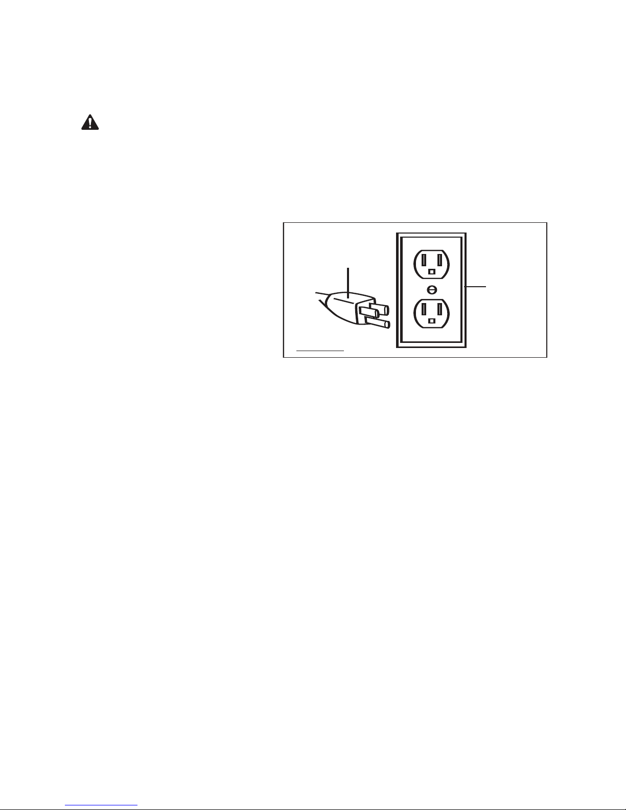
5. Plug the power plug (74) into the nearest 120 volt, grounded, electrical outlet.
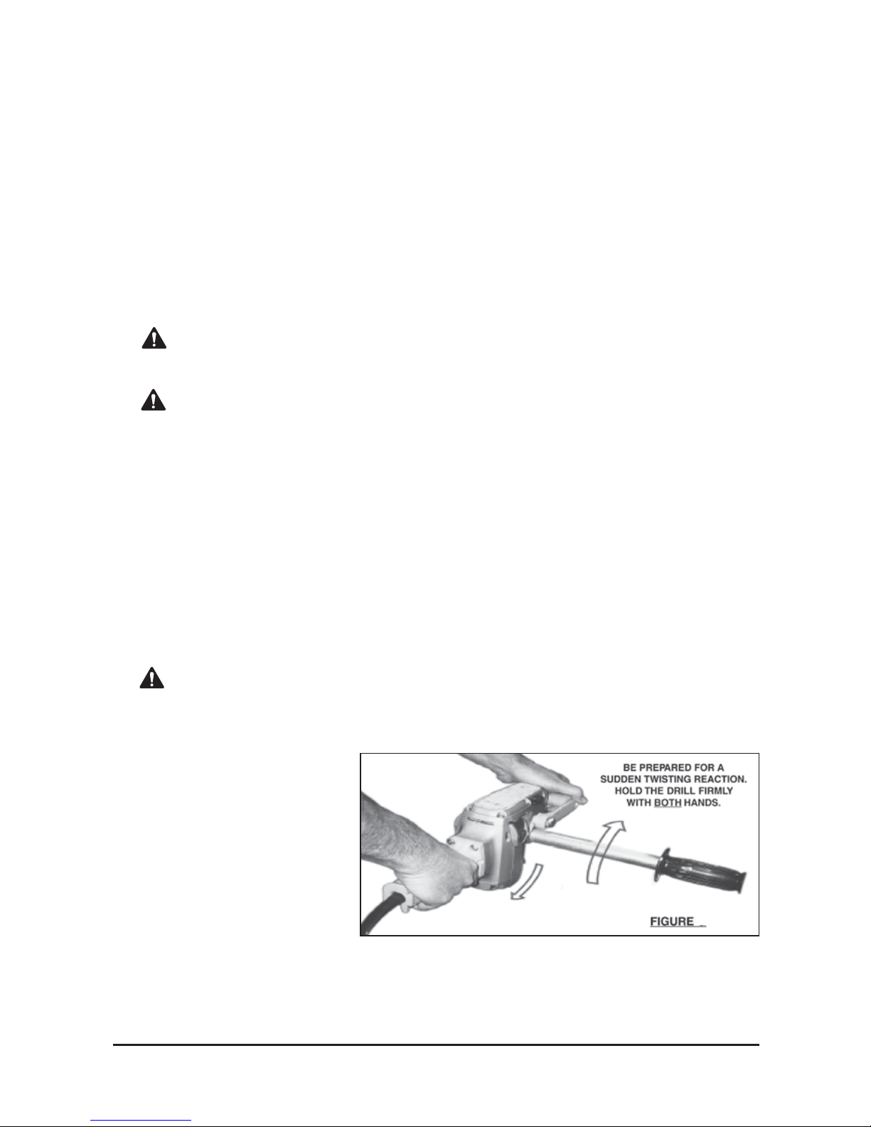
6. When using the drill, always maintain a firm grip on the tool with both hands as torque
from the drill’s motor will cause the drill to twist.
7. Make sure the drill bit lightly touches the point on the workpiece where the hole is to be
drilled prior to squeezing the power switch (69) of the drill.
8. While the drill is running, apply light downward pressure on the drill. Do not attempt to
force the drill to cut faster than it was designed to cut.
9. CAUTION! Always be prepared for a sudden twisting reaction of the drill. Never place
your hands, or other body parts, between the part of the drill being braced and the object
it is being braced against. Hands, or other body parts, that are in the direct path of a
twisting reaction can be pinched, crushed and broken. Minimize the chances of a sudden
twisting reaction by: using
the proper drill bit for the job,
using sharp drill bits, setting
the speed switch Lever (34) to
the proper speed for the size
of drill bit, avoiding knotty,
warped, or wet workpieces,
and avoiding hidden nails or
other objects in the workpiece.
(See Fig. F)
10. As soon as the drill bit cuts completely through the workpiece, remove the drill bit from
the hole while the drill is still running . This helps keep the drill bit from becoming
jammed in the hole.
11. Release pressure on the power switch (69) to stop the drill, and unplug the drill from its
electrical outlet. Remove the drill bit. Then store the drill in a clean, dry, safe location.
F

7
MAINTENANCE
WARNING! Always make sure the power switch (69) is in its “OFF” position, and
disconnect the drill from its electrical outlet before performing any inspection,
maintenance, or cleaning.
• Before each use, inspect the general condition of the drill. Check for loose screws,
misalignment or binding of moving parts, cracked or broken parts, damaged power cord
(74), loose, dull, or bent drill bits, and any other condition that may affect the safe
operation of the drill. If abnormal noise or vibration occurs, have the problem corrected
before further use. Do not use damaged equipment.
• Daily: With a soft brush, cloth, or vacuum, remove all dust and debris from the drill. Then,
use a premium quality, lightweight machine oil to lubricate all moving parts. Do not
immerse any part of the drill in liquids.
• To replace the motor carbon brushes: It may become necessary at sometime to
replace the two carbon brushes (19) when the motor performance decreases, or stops
working completely. The carbon brushes are located on each side of the housing (50). To
do so, remove the two brush caps (20). Then remove the carbon brush from the right
brush holder (18), and remove the carbon brush from the left brush holder (70). If the
carbon brushes are worn down more than 1/2, replace both carbon brushes. If, however,
the carbon brushes are just dirty they may be cleaned by rubbing them with a pencil
eraser. When installing the carbon brushes, make sure the carbon portion of the carbon
brushes contact the motor armature, and that the springs face away from the motor. Also,
make sure the springs operate freely. After cleaning or replacement, replace the brush caps.
• After approximately six months to one year (depending on use) return the drill to a
qualified service technician for the following: A thorough mechanical inspection and
cleaning of the internal gears, spindles, bearings, housing, etc. A thorough inspection of
the power switch, power cord and plug, and motor armature. A thorough testing proce-
dure to ensure proper mechanical and electrical operation.
• When storing, always keep the drill in a clean, dry, safe location out of reach by children
and other unauthorized personnel.
WARRANTY
One Year Warranty
For warranty questions, call 1-800-222-5381

NOTE: Some parts are listed and shown for
illustration purposes only, and are not available
individually as replacement parts.
40
26
39
38
37
57
56
55
54
53
52
24
41
42
43
44
45
74 73 72 26
71
26 58
59
46
26
47
48
49
51
60 61
62 63
50
64 65
66
67
21
20
19
18 17
16
15
14
13
12
11
1
2
3
4
5
6
7
8
9
10
36
35
34
33
32
31
30
29
28
27
25
26
68
69
20 19 70
DIAGRAM & PARTS LIST
9

tr na oP itpircs ye tD Q tr na oP itpircs ye tD Q
g1 niraeBelde 9e 1 rN e3 voCrew 1oL
g2 niraeBrell 0o 1 wR 4 ercS 4
3 raeG 1 14 wercS 1
4 rae r22G e4 hsaW 1
5 yeK 1 3 k4 cuhC 1
6 rae r41G e4 hsaW 1
r7 ehsaW 1 54 etalP 4
g8 niraeBelde 6e 1 wN 4 ercS 2
r9 ehsaW 1 7 g4 nirpS 2
g0 n1 iraeBelde 8e 1 eN v4 eelSgnir 1pS
1 el1 dni 9p 1 gS n4 iraeBrell 1oR
2 r1 ae g01G n5 isuo 1H
g3 n1 ihs 1u 1 gB n5 ihsuBrota 1tS
g4 n1 iraeBeldeeNtsur 2h 1 gT n5 iraeBrell 1oR
e5 l1 dnaHtno 3r 2 eF r5 utam 1rA
r6 e1 hsa g42W n5 iraeBrell 1oR
71 tlo r52B e5 hsaWkcoLgnir 1pS
r8 e1 dloHhsurBnobraCthg 6i 1 rR 5 otatS 2
h9 s1 urBnobr 7a 2 wC e5 rcSgnippaT-fl 1eS
p0 a2 Chsu 8r 1 wB 5 ercS 3
e1 l2 dnaHe
d 9i 1 eS l5 dnaHraeRthg 1iR
y4 e2 Kkcu 0h 1 nC i6 Prednil 1yC
5 w2 erc n16S i6 Prednil 1yC
r6 e2 hsa 9 r21W e6 hsaW 1
r7 e2 voCp 3o 1 wT 6 ercS 4
g8 n2 iraeBelde 4e 1 wN 6 ercS 4
g9 n2 iraeBeldeeNtsur 5h 1 rT e6 hsaW 1
g0 n3 ihs 6u 1 e6B riW 1
1 r3 aeG 1 76 eriW 1
t2 r3 oppuSra 8e 1 eG l6 dnaHraeRtf 1eL
g3 n3 iraeBeldeeNtsur 9h 1T h6 ctiwSgnisreveR/hctiwSrew 1oP
r4 e3 veLhctiwSdee 0p 1 rS e7 dloHhsurBnobraCtf 1eL
5 g3 nirpS 1 17 wercS 2
6 w3 erc e22S t7 alPdroCcirtce 1lE
g7 n3 ihsuBrota 3t 1 rS e7 dloHdroCcirtce 1lE
t8 e3 ksa g41G u7 lPdroCrew 1oP
10

Distributed by
Northern Tool & Equipment Co., Inc.
Burnsville, MN 55306
NorthernTool.com
Made in China
WARRANTY
One-year Limited Warranty
Table of contents
Other Klutch Drill manuals