-1-
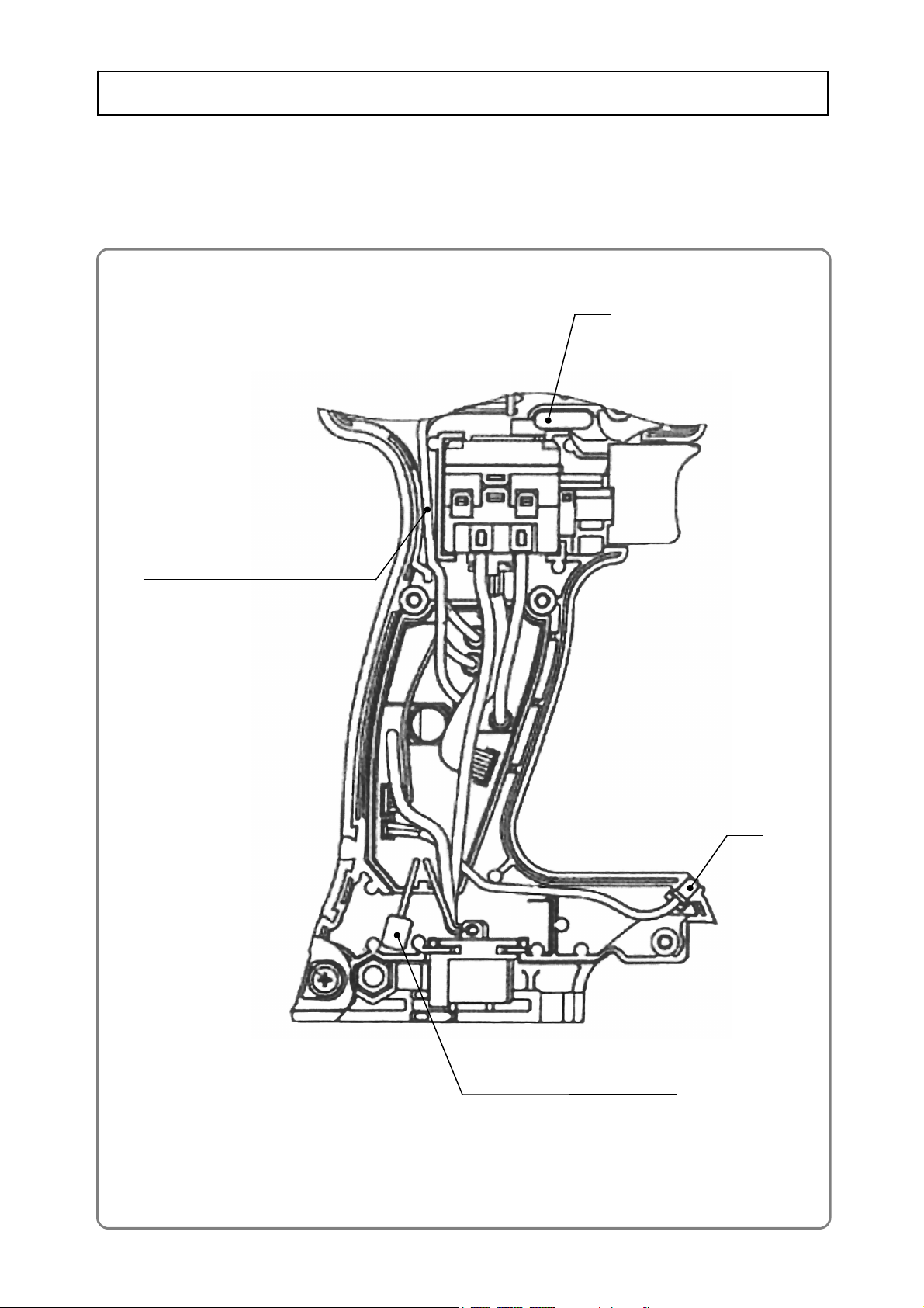
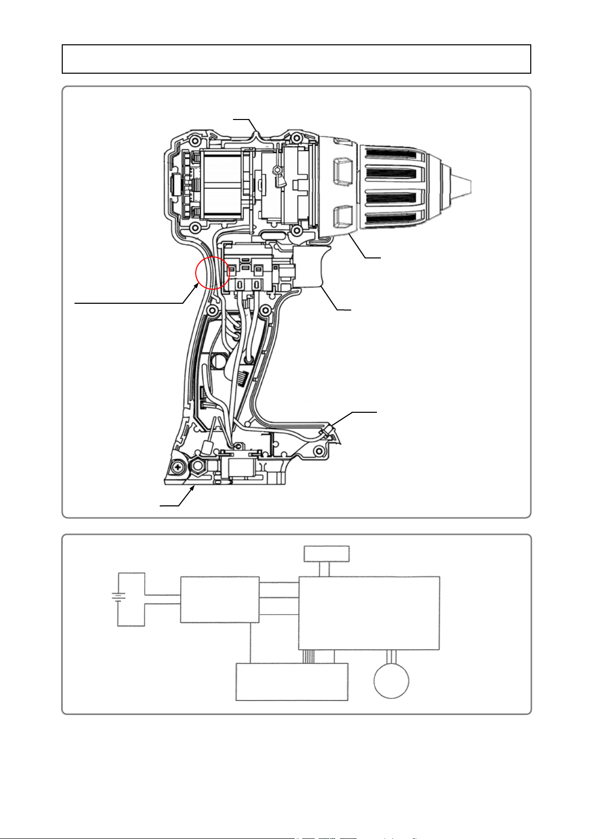
• Removal of the drill chuck
[2]
Clutch dial
WARNING: Always remove the battery from the main body before starting repair or maintenance
work. Because the tool is cordless, inadvertently activating the switch with the battery
left in the main body will start the motor rotating unexpectedly, and could cause serious
injury.
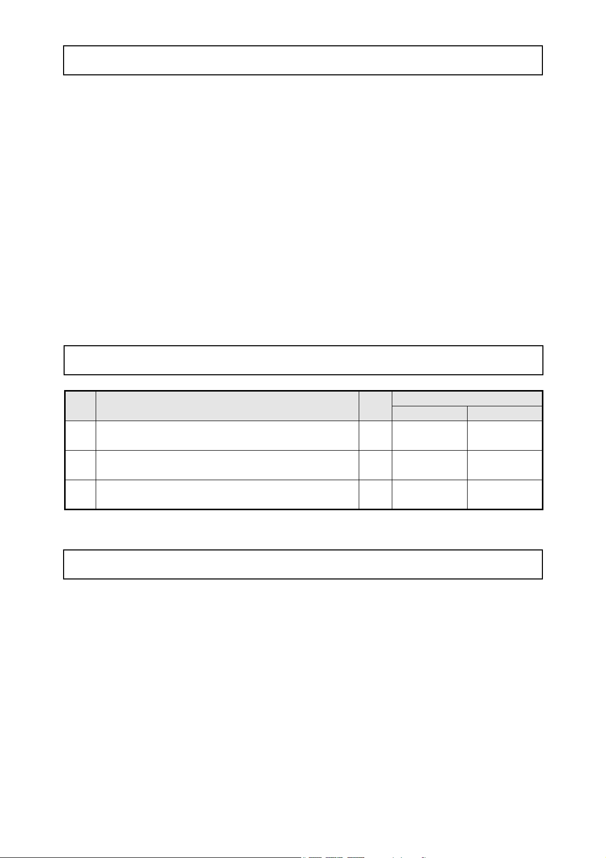
1. Precautions on disassembly and reassembly
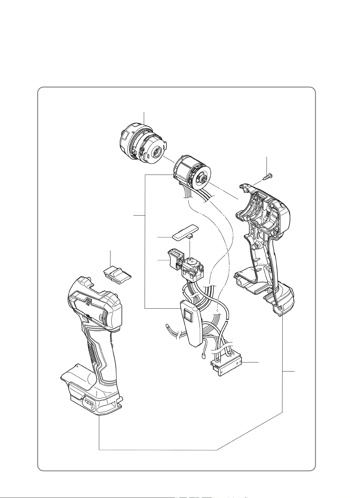
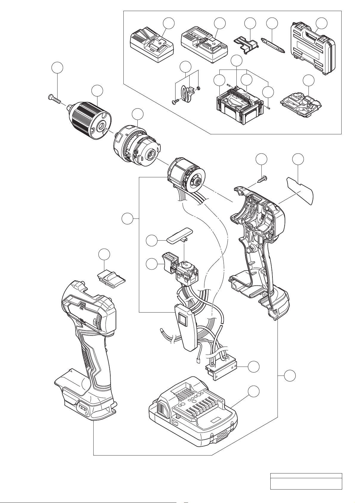
[Bold] numbers in the description below correspond to the item numbers in the parts lists and exploded
assembly diagrams for the Models DS 18DD and DS 18DDX.
1. Removal of the drill chuck
(1) For removal of the Drill Chuck [2] from the drill body, first use a vise to clamp the drill body, and then go
to steps (a) and (b) below. A cloth should be placed between the drill body and the vise to protect
Housing (A).(B) Set [11] against damage.
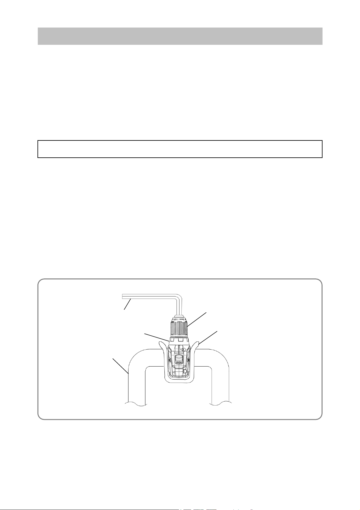
(a) Fully open the jaw of the Drill Chuck [2], and then use dedicated driver bit T25 (T-shaped
hexalobular screw) to turn the Left-Hand Hexalobular M5 [1] clockwise and remove it.
NOTE: The Left-Hand Hexalobular M5 [1] is a left-hand threaded screw. Use of a driver bit
other than T25 may strip the screw thread and thus prevent the removal of the Drill
Chuck [2]. To avoid this situation, be sure to only use dedicated driver bit T25.
(b) Insert an 8 mm hex. bar wrench into the top of the Drill Chuck [2], clamp it as shown below, and then
turn the wrench counterclockwise to detach the chuck. Use a pipe or other means of leverage in
case the chuck is difficult to loosen.
(2) Set the clutch dial to the clutch “1” position.
Disassembly
REPAIR GUIDE
Cloth
8 mm hex. bar wrench
Vise