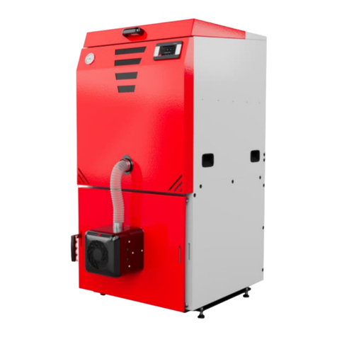
KOTLOSPAW SlimKo MAX Series User manual

1
“KOTŁOSPAW”
63-300 Pleszew
ul. Szenica 38
OPERATION AND MAINTENANCE MANUAL
Operation and assembly manual
ORIGINAL
District heating water boilers
with a pellet burner
“SlimKo MAX”……... kW
Factory No. …………….
Note!
The boilers comply with the following requirements:
emission limit values acc. to PN-EN 305-5: 2012- class 5 5
ecological design
energy efficiency –A+ class
Read this manual carefully before installation and use of the boiler.
ATTENTION!
Incorrect protection of the boiler may result in severe damage to the same and expose
its user to danger
The following protection should be used for SlimKo MAX boilers:
- in open heating system acc. to PN-91/B-02413
- w closed heating system acc. to PN-EN 12828
NOTE: In case of any doubts and other suggestions as to provisions of this manual, please
Always install and use the boiler in adherence to the current provisions of law and
standards.
Edition 2
July 2020

2
SPIS TREŚCI
1.INTRODUCTION.................................................................................................................................... 4
1.1. General information..................................................................................................................... 4
1.2. General principles of use and warranty conditions ..................................................................... 5
1.3. Specifications of delivery.............................................................................................................. 6
1.4.Transport of the boiler .................................................................................................................. 6
2. DESCRIPTION AND INTENDED USE..................................................................................................... 6
3. TECHNICAL AND OPERATING PARAMETERS...................................................................................... 7
4. SELECTION OF A BOILER FOR A HEATING SYSTEM ............................................................................ 7
4.1.Specific heat demand indicators for housing buildings. ............................................................... 7
5. TYPES OF FUELS................................................................................................................................... 7
6. DESCRIPTION OF THE BOILER STRUCTURE......................................................................................... 8
6.1. Types of protections for the boiler............................................................................................. 10
6.2. Safety systems of the burner ..................................................................................................... 11
7. INSTALLATION OF BOILERS IN THE SYSTEM..................................................................................... 11
7.1. Erection of the boiler.................................................................................................................. 11
7.2. Ventilation of the boiler room.................................................................................................... 12
7.3. The exhaust gas system.............................................................................................................. 12
7.3.1. Exhaust gas discharge.......................................................................................................... 13
7.3.2. Essential equipment of chimneys as required by provisions of law.................................... 13
7.3.3. Fire protection requirements................................................................................................ 14
7.3.4. Static and strength properties .............................................................................................. 15
7.3.5. Selection of a chimney system solution .............................................................................. 15
7.3.6. Selection of a diameter of the chimney............................................................................... 16
7.4. District heating system............................................................................................................... 16
7.5. Protection of the boiler in an open heating system................................................................... 16
7.6 Requirements for SlimKo MAX boilers protected in a closed heating system with a diaphragm
vessel................................................................................................................................................. 21
7.6.1. A relief and filling valve...................................................................................................... 21
7.6.2. Requirements relating to assembly...................................................................................... 21
7.6.3. Safety requirements............................................................................................................. 22
7.6.4. Inspection requirements before commissioning.................................................................. 22
7.6.5. Requirements relating to use as provided for by UDT [Technical Supervision Authority] 23
7.6.6. Technical data...................................................................................................................... 23
7.6.7. The system diagram............................................................................................................. 24

3
7.6.8. Guidelines relating to selection of diaphragm expansion vessels (closed systems) under
PN-EN 12828:2003 –appendix D................................................................................................. 25
7.6.9. A residual risk ..................................................................................................................... 30
7.6.10. Causes of a residual risk and methods of elimination of the same.................................... 30
8. ELECTRICAL SYSTEM.......................................................................................................................... 31
9. FILLING WITH WATER ....................................................................................................................... 32
10. LOW-TEMPERATURE CORROSION.................................................................................................. 32
11. TECHNICAL AND OPERATIONAL DATA........................................................................................... 33
jednopalnikowy –single-burner dwupalnikowy –double-burner ...................................................... 34
12. START-UP OF THE BOILER............................................................................................................... 34
12.1. Preliminary tests....................................................................................................................... 35
12.2 Firing-up the boiler.................................................................................................................... 35
12.3 Replenishment of fuel ............................................................................................................... 35
13. POWER ADJUSTMENT..................................................................................................................... 36
14. BASIC CONDITIONS OF SAFE USE ................................................................................................... 36
15. DISORDERS IN OPERATION OF THE BOILER –MOST FREQUENT PROBLEMS AND REMOVAL OF
THE SAME.............................................................................................................................................. 37
15.1 Basic causes of interferences and insufficiencies in operation of the boiler include: .............. 37
16. CLEANING AND MAINTENANCE OF THE BOILER............................................................................ 39
17. FIRE SAFETY CONDITIONS............................................................................................................... 40
18. EMERGENCY STOP OF THE BOILER................................................................................................. 40
19. SHUTTING DOWN THE BOILER ....................................................................................................... 41
20. FINAL COMMENTS .......................................................................................................................... 41
21. ENVIORNMENTAL PROTECTION..................................................................................................... 42
22. RESIDUAL RISK ................................................................................................................................ 42
22.1. Causes of a residual risk and methods of elimination of the same. ........................................ 42
23. CONDITIONS OF SAFE USE OF THE BOILERS .................................................................................. 44
24. WARRANTY CONDITIONS............................................................................................................... 46
25. WARRANTY DOCUMENT ................................................................................................................ 51
26. PROTOCOL OF START-UP OF THE BOILER ...................................................................................... 52
27. THE PRODUCT CARD....................................................................................................................... 55
PN-EN 303-5:2012 ................................................................................................................................. 55
28. ECODESIGN INFORMATION CARD.................................................................................................. 56

4
1.INTRODUCTION
The purchased heating device is a latest generation district heating water boiler that complies
with requirements of EU directives, regulation and standards at the highest European level
and Polish provisions of law.
The boilers comply with requirements of:
emission limit values acc. to PN-EN 305-5: 2012- class 5
ecological design
energy efficiency –A+ class
The Polish legislation has already introduced application of requirements relating to
ecological designs, which sheds a good light on Polish manufacturers and our company as
regards environmental protection and anti-smog policy.
1.1. General information
The Operation and Maintenance Manual is an operation manual relating to automatically
stoked heating boilers for solid fuels and for users of SlimKo MAX district heating water
boilers with a pellet.
For correct and safe functioning of the boilers, it is necessary to read this OMM, which
includes information about the structure, installation and method of use of the boilers.
For automatic and failure-free work, it is essential to use a state-of-the-art and high-class
burner and controller. Information given in this OMM and relating to the above-mentioned
devices is general and detailed information can be found in the device operation manuals
constituting an integral part of the boiler operation manual.
Before commencement of installation of the boiler and use of the same, a user should
perform the following activities:
- read carefully this OMM relating to the boiler, controller, burner and other devices
installed for the boiler
- check contents of supplied equipment and compare rating plate data with a warranty
document,
- check the boiler or its equipment for any damage during transport.
The boiler has a rating plate located in a visible place and containing the following
information:
- the manufacturer’s name and address,
- the boiler trademark and type,
- production number and year,

5
- nominal thermal power,
- boiler class,
- maximum admissible working pressure in bars,
- max. working temperature in °C,
- water volume in litres,
- power supply [V, Hz, A] and power consumption in [W],
- fuel class acc. to PN-EN 303-5.
SlimKo MAX boiler is equipped with a modern pellet feeding and burning burner and
combustion process controller. It features unique solutions and innovative positive pressure
combustion technology, which eliminates the problem of back burning. Such solutions
improve the combustion process and result in lesser fuel combustion and favour maintenance
of comfortable temperature in heated rooms.
A burner should be installed and particular devices of the district heating system should be
connected to a controller and boiler by the manufacturer or the manufacturer’s authorized or
trained service worker.
A warranty is granted for the boiler. Detailed conditions of the warranty are specified in this
manual and attached warranty document.
The boiler is a heating device, in case of which, despite numerous technical protections and
recommendations and information relating to safe use, there is always a potential risk of skin
burning or fire and, therefore, before attempting to do any activities, users should always
adhere to basic principles of safety and act with particular caution.
OMMs and declarations of compliance for the burner, controller and other appliances
included in the boiler equipment constitute an integral part of this OMM.
1.2. General principles of use and warranty conditions
SlimKo MAX boilers are intended for installation in contained spaces such as boiler rooms. It
is prohibited to use the boiler for other purposes and purposes contrary to this OMM. The
boilers should be used, operated and repaired by persons of legal age. Operators of boilers
above 50 kW have to hold valid operation licence (Regulation of the Minister of Economy,
Labour and Social Policy as of 28 April 2003, Journal of Laws of 2003, No. 89, item 828). A
user shall be responsible for obligations of operation and safety and he/she should comply
with all requirements provided in OMM. In order to start the boiler, a user should read the
operation Manuela for a burner, controller and other elements of equipment in order to
understand their principles of operation and comply with all provided principles of use.
Provisions relating to prevention of accidents and all basic occupational health and safety
provisions always have to be complied with.
NOTE!
No interferences and irregularities in operation of the boiler as resulting from a failure to read
this OMM shall be subject to a complaint.
These include in particular:
- a choice of an inappropriate boiler for the heated building or facility,
- incorrect connection of a boiler and incorrect district heating system delivered,
- use of inappropriate fuel (type, granulation, calorific value),
- incorrect control of the combustion process
- protection of a boiler in an open heating system contrary to PN-91/B-02413
- protection of a boiler in a closed heating system contrary to PN-EN 12828
- use of a chimney that does not comply with requirements,

6
- a failure to clean or maintain a boiler,
- mechanical damage,
- incorrect ventilation of a boiler room.
1.3. Specifications of delivery
The boiler is delivered as a compact device comprising the body, burner, fuel tank and
equipment. The boiler body is connected to the equipment and protected by mineral wool
thermal insulation covered with a protective steel sheet jacket constituting an aesthetic
enclosed whole. An integral part of the burner is a burner designed for pellet burning, fuel
tank, pellet feeder, controller, OMM and warranty documents. A complete delivery includes:
- the boiler body –a heat exchanger with complete insulation
- a fuel tank –can be delivered as a bunker in a boiler room
- a KIPI ROTARY pellet burner
- an external pellet feeder
- a fan integrated with a burner
- a controller –PLUM ecoMAX 860 P3-C
PLUM ecoMAX 860 P3-C TOUCH (touch panel, option)
- PLUM ecoMAX 850C4 cascade controller (option)
- a thermometer with capillary tube
- the boiler operation tools
- operation manuals for the boiler and subassemblies
For protection of the boiler in a closed heating system with a membrane expansion vessel,
additional equipment is included in the set (option):
- a safety valve - SYR 1915
- thermal protection –SYR 5067
1.4.Transport of the boiler
The boiler should be protected for transport against dislocation and toppling on the a vehicle
platform with the use of straps, wedges and wooden blocks attached to the vehicle platform,
the boiler should be transported in a horizontal position. The boiler should be lifted and
lowered with the use of lifting lugs, which are included in the boiler, as well as with the use of
mechanical hoisters and cranes.
2. DESCRIPTION AND INTENDED USE
SlimKo MAX heating boilers for solid fuels are equipped with a high-class pellet burner and
automatic control system and combustion process control system and are intended for
supplying power to district heating systems in various types of facilities and preparation of
hot water.
They were designed and delivered as boilers with thermal power of up to 500 kW and are
intended mainly for facilities that show demand for appropriate power. They can operate in a
gravitational system or pump system.
The boilers guarantee a much higher comfort of use than traditional boilers due to their
automatic feeding and fuel firing-up. The modern structure of a tubular heat exchanger
ensures high thermal efficiency for small sizes and use of renewable fuels helps to protect

7
natural environment. Being fully automated boilers, they constitute an economical alternative
both to gas, oil and coal boilers.
3. TECHNICAL AND OPERATING PARAMETERS
SlimKo MAX boilers comply with the latest European and national standards, which impose
high requirements relating to emission, effectiveness and efficiency of boilers. Requirements
for an ecological design relate to loading of a boiler for nominal power of 100 % and
minimum power of 30%. Thermal and emission parameters for low loading are very
significant, as, in heating seasons, boilers are loaded up to 50% on average. Attention should
also be drawn to high and stable efficiency of more than 90% in operation from nominal and
minimum loading.
The boilers are characterized with a simple integrated structure and intuitive and simple
operation due to their automatic and controlled fuel feeding systems, which allows, among
others, for smooth control of thermal efficiency of the boiler and obtaining of desired
temperature of outlet water. Basic operation involves control and feeding of fuel in a tank and
removal of small quantities of ash.
NOTE!
SlimKo MAX boilers should be protected only under the following:
- an open heating system acc. to PN-91/B-02413. Heating and district heating. Protection of
open system water heating systems. Requirements.
- a closed heating system ac. to PN 12828. Heating systems in buildings. Designing of district
water heating systems.
The boilers comply with requirements of EU directives relating to safety of products as
confirmed by certificates of compliance and “CE” mark.
4. SELECTION OF A BOILER FOR A HEATING SYSTEM
In order to select a proper boiler, a user should consider calculated heating demand resulting
from heat loss by penetration as well as heating for ventilation and hot water purposes. A heat
balance for a building should be prepared by a designer in accordance with the current
standards.
NOTE!
The manufacturer shall not be liable to inappropriate selection of a boiler.
4.1.Specific heat demand indicators for housing buildings.
For determination of estimate heating demand for a housing building, one may adopt average
values of the below mentioned specific heat demand indicators.
- q= 75 - 100W/m² - for averagely insulated buildings (aerate concrete walls, layered walls
without thermal insulation, double windows)
- q= 50 - 75W/m² - for well insulated buildings (insulated aerate concrete walls, insulated
windows with glazing units, “hot” floors).
5. TYPES OF FUELS
Basic fuel used in SlimKo MAX boilers is pellet. Following each change (supply) of fuel or in
case that incorrect operation is found, one should do so-called “FEEDER TEST” absolutely

8
(see the burner operation manual), which has a significant influence on correct and failure-
free operation of the device. Detailed requirements relating to pellet quality and
characteristics are given in the instruction manual for a boiler burner used.
Fuel with the following characteristics should be supplied to the burner:
Fractions
granulate
Diameter
6±1mm
Length
3.15 mm ÷ 40 mm
Dust quantity
≤ 1%
Bulk density
≥ 600 kg/m³ – 700 kg/m³
Humidity
≤ 12%
Calorific value
> 17 MJ/kg
Ash
≤0.5%
Selecting fuel, special attention should be paid to fuel originating from uncertain sources,
possible contents of mechanical inclusions in the form of stones or other non-flammable
inclusions that worsen burning quality. Pellets have to be supplied and transported in
absolutely dry conditions. Under the influence of humidity, granulates lose their quality and
are hardly flammable. Pellets should be stored in dry rooms protected against outdoor
conditions.
NOTE!
Use only fuel (pellet) of the type and characteristics given in the burner operation manual
(OMM), which was used for the boiler. If worse fuels are used, such problems as combustion
difficulty, reduction of efficiency of the boiler and premature destruction of the boiler and
burner should be expected. The boiler is not intended for incineration of waste and other fuels.
6. DESCRIPTION OF THE BOILER STRUCTURE
The boiler is made of a body referred to as a heat exchanger with a burner, controller and
thermal insulation, all constituting an integral whole. A fuel tank with a feeder may be
delivered as mobile or stationary as installed, for example, in other room.
The body has a box-like structure and has been delivered as bent and welded, which reduces
the number of welded joints affecting the process of production of the device. It is composed
of a furnace with an ash pit and convection part. Additionally, it is equipped with a door, flue,
stub pipes and ash pit. The furnace constitutes one chamber with a burner and spiral fuel
feeder, drive, fan and stoker. Above the furnace there is a double pipe heat exchanger
connected with the furnace in its back part.
The feeder is to feed fuel to the burner head and burn in the boiler furnace. Under the burner
there is an ash pit, into which ash falls by rotating and gravitational force. The ash pit may be
equipped (optionally) with an automatic ash remover. Air necessary for the combustion
process is supplied by a blowing fan that is connected with the burner and supplies the air in
the fuel zone. A controller controls operation of the boiler and fuel feeding system. Around
the burner there is a convection and furnace part of the heat exchanger. The convection part is
connected with a flue through the first and second pass of smoke-tubes. The structure and
measurements of the boilers are presented in figure 3 and table 4. The boiler structure allows

9
for periodical cleaning of the surface of the furnace heat exchanger through the furnace door
as well as smoke-tube passes through the cleanout door as well as the flue through the flue
inspection hole. All manholes are locked with the use of thermally insulated doors or covers.
Mechanical parts and drives of the feeder are covered and safe.
The furnace
The furnace constitute a combustion chamber with an ash pit. Around the combustion
chamber there is a water jacket, above which smoke-tubes are installed. In the front of the
furnace there is a furnace door, in which a burner is installed.
The convection part
The convection part features a horizontal tubular heat exchanger located in the water space
above the furnace, thus constituting two convection passes. Exhaust gases from the furnace
chamber flow into the vertical reversal channel at the end of the furnace and, then, through the
first pass of smoke-tubes they get into the front reversal chamber. From the front reversal
chamber they get, through the second pass of smoke-tubes, into the flue. The structure of the
heat exchanger features a developed heat exchange surface. A change of direction and speed
of flow of exhaust gases leads to separation of volatile fractions (dusts) and reduction of
emission of the dusts into natural environment. As a result of the solution, an appropriately
oriented circulation of exhaust gases leads to intensification of heat exchange and high
efficiency of the boiler.
The front furnace door
The front furnace door is located in the front of the boiler and it closes the entire area of the
furnace and convection part. A burner is installed in the door. The door has handles for safe
opening as well as pressure and tightness for closing. Once opened, the door provides an
access to the burner and internal space of the boiler (furnace) which makes it easy to
cooperate, clean the furnace and remove the ashes and other contamination from combustion
and cleaning of the boiler.
ATTENTION!
The furnace door may not be opened during operation of the boiler.
The front manhole of the cleanout
The cleanout manhole is located in the front part of the boiler in the reversal (settling)
chamber zone. The cleanout manhole is used for closing the reversal chamber of exhaust
gases from the first to the second pass of exhaust gases. Once opened, the cleanout manhole
provides an access for cleaning of smoke-tubes of the first and second pass and settling
chamber.
The back manhole of the cleanout
It is located under the flue and is used for inspection of the reversal channel. The manhole is
equipped with an optical inspection hole for observation of the burner flame.
Thermal insulation and enclosure
Thermal insulation is made of mineral wool placed in steel sheet cassettes that are coated or
painted on both sides, thus ensuring safe temperature of the external surface, contained
enclosure and aesthetic appearance.
The flue

10
The flue is located in the top part of the boiler at the back and constitutes an element that
connects the boiler with the chimney. The flue outlet is directed backwards as standard. For
safety reasons, the flue is not equipped with an exhaust throttle.
The stub pipes
The boiler is equipped with stub pipes ending with a thread or power supply, return and drain
flanges as well as water meter chambers. The boiler has a supply stub pipe on the top and a
return stub pipe at the bottom as carried out at the back of the boiler. Next to the return stub
pipe, there is a coupler to be used in the system as a drain stub pipe. In the top part of the
boiler under the insulation there are inspection chambers of STB temperature sensor.
The burner with a feeder
The burner with a feeder is installed in the door in front of the boiler. The feeder is to feed
fuel from the tank to the burner head located in the furnace. Fuel is fed with the use of a
special gear-motor powered spiral feeder.
The pellet burner is characterized by:
- high safety as regards control of temperature and back burning
- a reliable combustion system
- a modern control system for firing-up and flame control with power control
- automatic leaning of the combustion chamber
The fuel tank
The fuel tank located next to the boiler has been designed as free standing and made of steel
sheet. Its special shape makes fuel flow down. Depending on an option, it can be equipped
with a locking cover or be delivered as an open tank.
NOTE!
An appropriate fuel level should be maintained, i.e. min. ¼ of the tank capacity.
A microprocessor controller
It is located on the boiler enclosure. Through a system of sensors installed in the boiler and
burner, it controls the fuel feeder operation according to water temperature in the boiler as set
by a user in accordance with the current demand and not exceeding the admissible value given
in the operation manual. The controller is also equipped with boiler emergency stop sensors in
case of any emergency conditions.
The controller is a modern electronic device designed for the boiler operation control in
consideration of specificity of pellet burning.
6.1. Types of protections for the boiler
The controller is equipped with emergency sensors and it stops the boiler and signals
emergency conditions with a light or sound impulse on the panel in the following cases:
- exceeding of maximum admissible temperature of water in the boiler,
- lack of fuel leads to stopping of the whole system and burner damping,
- back burning is prevented by feeding of duel into the burner,
STB thermal protection is a water temperature limiter that prevents exceeding of the
temperature by stopping the boiler completely, if maximum admissible temperature is
reached. Owing to the use of STB protection, operation of the limiter can only be restored
manually, which conditions restarting to the boiler and further operation of the same. In case
of restarting of the burner, a cause of stopping of the boiler due to overheating of the boiler

11
should be checked, evaluated and appropriate steps should be taken in order to remove the
cause.
6.2. Safety systems of the burner
The burner is equipped with the following safety systems that protect a user against back
burning. The main protections include:
- a burner temperature sensor, which, after detecting the temperature of the heating agent
exceeding 90o C, proceeds from the operation mode to damping mode, thus stopping
an external feeder and setting the fan to 100% of power.
- a flexible feeding pipe, which constitutes a flexible connector between the external feeder and
burner itself. Its main task is to feed fuel to the burner and, additionally, it functions as a
protection against back burning. Under influence of high temperature, the pipe will melt, thus
preventing further fuel feeding.
7. INSTALLATION OF BOILERS IN THE SYSTEM
Before connecting the boiler to the heating system, a user should read the operation manual
carefully and check, if all sub-assemblies are operational and the boiler equipment is complete
in accordance with the delivery specifications. SlimKo MAX boilers should be installed in
accordance with the operation manual for the boiler, the boiler room design, requirements
relating to ventilation and combustion gas exhaust system as well as quality of water supplied
to the boilers. The boiler room should be located and equipped in accordance with standards
relating to “Solid fuels boiler rooms”. An installing company should perform a tightness test
before assembly of the boiler for 10 minutes at the pressure of 3 bars.
NOTE!
For safety, all boiler systems should be delivered with particular diligence, with the use of
state-of-the-art and recognized engineering practices. The boiler should be protected only in
adherence to:
- PN-91/B-02413 –an open heating system
- PN 12828 –a closed heating system.
7.1. Erection of the boiler
Due to its measurements and weight, the boiler should be transported to its destination with
particular caution. Pipes laid on the floor should be used for transportation. The transport
activities should be administered by one responsible person, preferably an experienced fitter
responsible for installation of the boiler. The person should be responsible for selection of the
method and arrangements of transport and erection of the boiler. If necessary, the burner can
be disassembled.
The method of transport and erection of the boiler should be adjusted to local condition,
condition of the surface, obstacles, slopes etc. Particular attention should be paid to safety of
legs and hands and possible toppling of the boiler. Generally, boilers do not require laying any
foundations and they can be erected directly on a non-flammable floor. It is recommended
that the boiler should be levelled carefully and the strength of the ceiling and floor, on which
it is erected should be sufficient as regards the weight of the boiler with water. The boiler
should be erected in the floor made of non-flammable materials.
NOTE!

12
One should provide for an easy access to the boiler from all sides and, in particular, in the
front so that walls or objects surrounding the boiler or building walls could not impede fuel
feeding, cleaning of the burner, furnace, ash pit, convection channels and removal of waste.
7.2. Ventilation of the boiler room
Good operation of the boiler is conditioned, among others, upon sufficient supply of fresh air
and, therefore, the boiler room should have appropriate gravitational ventilation outlets above
the floor and under the ceiling. A room, in which the boiler is erected should comply with
requirements relating to ventilation for the type of facilities as well as provisions of law and
standards.
Basic tasks of ventilation in a district heating boiler room include:
- supply of sufficient quantity of air both for combustion and ventilation purposes
- dilution of concentration of harmful gases, if such are emitted in the combustion process
inside the boiler room and removal of the gases outside
- ensure such quantity of indoor air as is necessary for elimination of any risks for the boiler
room operators
ATTENTION!
It is prohibited to use mechanical exhaust ventilation systems in the boiler room.
7.3. The exhaust gas system
The chimney system connected to devices manufactured by Kotłospaw has to comply with
requirements of the current Building Law and associated regulations and standards as of the
assembly date. Basic guidelines relating to requirements for chimneys are included in the
Regulation of the Minister of Infrastructure as of 12 March 2009 relating to technical
conditions for buildings and their locations –Journal of Laws 2009/56/item 461.
Designing and selection of exhaust gas systems should also consider requirements of other
current standards and provisions of law, including, but not limited, to:
- PN-89/B -10425 Smoke, exhaust and ventilation pipes made of bricks. Technical
requirements and acceptance tests.
- PN-EN 1457-1:2012 Chimneys –Ceramic flue liners –Part 1: Flue liners operation under
dry conditions –Requirements and test methods
- PN-EN 13063-1+a1:2009 Chimneys - System chimneys with clay/ceramic flue liners - Part
1: Requirements and test methods for sootfire resistance
- PN-EN 13063-2+A1:2009 Chimneys - System chimneys with clay/ceramic flue liners -
Part 2: Requirements and test methods under wet conditions
- PN-EN 1443:2005 Chimneys –General requirements.
- PN-EN 1856-1:2005/A1:2007 Chimneys - Requirements for metal chimneys - Part 1:
System chimney products
- PN-EN 1856-2:2006 Chimneys - Requirements for metal chimneys - Part 2: Metal flue
liners and connecting flue pipes
- PN-EN 15287-1:2007 Chimneys. Design, installation and commissioning of chimneys. Part
1: Chimneys for non-roomsealed heating appliances
- PN-EN 1993-3-1:2008 Design of steel structures - Part 3-1: Towers, masts and chimneys
- PN-EN 13384-1:2015-05 Chimneys - thermal and fluid dynamic calculation methods - Part
1: Chimneys serving one heating appliance

13
- PN-EN 13384-2:2015-05 Chimneys - thermal and fluid dynamic calculation
methods. Chimneys serving more than one heating appliance
The regulation of the minister of home affairs and administration as of 7 June 2010 relating to
fire protection of buildings, other building facilities and areas, Journal of Laws 2010/109/item
719.
7.3.1. Exhaust gas discharge
Fulfilment of the condition guarantees correct operation of SlimKo MAX boiler. The boiler
has to be connected to an independent chimney with appropriate height and cross-section. The
height and cross-section should selected as based on technical information contained in OMM
of the heating appliance and requirements of PN-EN 13384 Thermal and fluid dynamic
calculation methods.
GUIDELINES;
- the connecting cable diameter of the flue cannot be reduced,
- due to low temperature of exhaust gases, one should consider only chimney systems that can
operate under wet condition with low absorption.
- connection to the vertical part of the chimney can only be made with the use of an Y-branch
(45 degrees).
NOTE!
Appliance manufactured by Kotłospaw are high-efficiency heating appliances and only
correctly selected diameter of the chimney can guarantee that the appliance will operate in
accordance with declared efficiency values.
Under the current provisions of the Building Law, every chimney system should be marked
with a CE mark and its manufacturer is obliged to issue a Declaration of Performance.
Marking with a CE mark and issue of a declaration of performance guarantees that a given
solution complies with fundamental requirements relating to safety of use, health protection
and environmental protection.
A user should select a chimney system, ensuring that its characteristics included in a
Declaration of Performance as issued by the chimney manufacture comply with requirements
for appliances manufactured by Kotłospaw and, in particular, those relating to temperature of
exhaust gases (temperature class), tightness (tightness class), resistance to condensate and
corrosion caused by products of solid fuels combustion.
GUIDELINES:
- a chimney system should be adjusted to operation under wet conditions,
- the used materials for an exhaust gas jacket should be resistant to any condensate resulting
from combustion of solid fuels.
NOTE!
Inappropriate selection of a chimney system may result in penetration of condensate through
the chimney walls.
7.3.2. Essential equipment of chimneys as required by provisions of law
Under the Regulation of the Minister of Infrastructure as of 12 March 2009 relating to
technical conditions for buildings and their locations –Journal of Laws 2009/56/item 461,
chimneys should be tight, equipped with inspection holes or inspection holes locked with a
tight door and a condensate drain system.

14
GUIDELINES:
- a vertical part of the chimney should be equipped with a condensate drain and inspection
hole at its base, allowing for removal of waste,
- the structure of the vertical part should prevent condensate and rainfalls from getting into the
connection (flue) and boiler,
- the vertical part of the chimney should have, along its entire length, a constant diameter and
any admissible deviation from vertical tis 30 degrees and, in justified cases, 45 degrees,
- every folding of the flue with its angle exceeding 45 degrees should be equipped with a tight
inspection hole.
NOTE!
Getting of condensate and waste from the vertical part into the boiler may result in quick
destruction of the boiler.
Chimney ducts should be carried above the roof at the height protecting against interference
with the draught. The requirements shall be deemed fulfilled, if the chimney duct outlets are
carried above the roof in the manner specified in PN-89/B -10425 Smoke, exhaust and
ventilation pipes made of bricks. Technical requirements and acceptance tests.
GUIDELINES:
- cowls protecting against reversal of draught should be used on smoke and exhaust pipes only
for buildings located in the 2nd and 3rd zone of wind load.
The chimney duct inlets should ensure an easy access to cleaning and periodical inspection.
GUIDELINES:
- in case of finishing or use of cowls, the structure of the elements has to enable insertion of a
cleaning brush or they have to be easily disassembled.
7.3.3. Fire protection requirements
Under the Regulation of the Minister of Infrastructure as of 12 March 2009 relating to
technical conditions for buildings and their locations –Journal of Laws 2009/56/item 461,
exhaust gas systems have to be made of non-flammable materials.
Due to fire safety, necessary distance from flammable materials of the chimney has to be
observed. Smoke and exhaust pipes should be installed far from flammable and exposed
structural parts of the building by at least 0.3 m and from plaster lining with the thickness of
25 mm on a grid or equivalent lining –at least 0.15 m.
NOTE!
In accordance with the structure of provisions of law, requirements of by-laws included in
appropriate legal acts, including in Regulation of the Minister of Infrastructure as of 12 March
2009 relating to technical conditions for buildings and their locations –Journal of Laws
2009/56/item 461, shall prevail.
Par. 34 of the regulation of the minister of home affairs and administration as of 7 June 2010
relating to fire protection of buildings, other building facilities and areas, Journal of Laws
2010/109/item 719 provides that in case of slid fuels boilers, solid contamination should be
removed at least once a month in collective catering and catering services institutions and at
least every 3 months in other institutions.
GUIDELINES :

15
- a vertical part of the chimney should be equipped at the bottom with an inspection hole
enabling removal of waste from the chimney,
- every folding of the flue with its angle exceeding 45 degrees should be equipped with a tight
inspection hole,
- the chimney base or crown should enable insertion of brushes/tools for cleaning of the
chimney.
7.3.4. Static and strength properties
An appropriate selection of the chimney and its diameter has a direct influence upon safety of
the appliance as well as proper and economical functioning of the same.
A user should adhere as mandatory to solutions and chimney systems with current approvals
to be presented by a supplier or a manufacturer of the chimney system.
Under the current provisions of the Building Law, every chimney system should be marked
with a CE mark and its manufacturer is obliged to issue a Declaration of Performance.
Marking with a CE mark and issue of a declaration of performance guarantees that a given
solution complies with fundamental requirements relating to safety of use, health protection
and environmental protection
7.3.5. Selection of a chimney system solution
Owing to their high efficiency, modern SlimKo MAX appliances manufactured by Kotłospaw
are suitable for a very low temperature of exhaust gases and require chimney systems
operating under wet conditions and characterized by low absorption. Carrying exhaust gases
into a traditional brick channel may, in a short period of time, result in destruction of the
channel and transudation of condensate through the chimney walls.
It is recommended that steel or ceramic system chimneys working under wet conditions and
highly resistant to condensate should be used.
In case of use of the existing chimney, it should be protected against destructive effects of
condensate with the use of a steel insert, check, whether the cross-section of the existing
chimney makes it possible to install an insert with an appropriate diameter that can guarantee
proper operation of SlimKo MAX boiler. The insert has to be insulated along its entire length
and the insulation thickness should be at least 20 mm. A system chimney insulated with air
and characterized with a small size and low weight can be used. The chimney has to be dry
and carefully cleaned before the installation.
If there is no appropriate shaft in place, an external steel chimney or system chimney with a
ceramic internal channel can be used and built indoors or outdoors.
In case of use of AGRO-PELLETS or pellets other than wooden and classified under DIN as
A1, attention should be paid to selection of the chimney system. Exhaust gases resulting from
combustion of the agro-pellets are characterized by high contents of chloride compounds,
which have destructive effects on most of acid0resistanc steel types, even at high
temperatures. In such cases, steel complying with DIN-EN 1.4539/ AISI 904L should be used
and the chimney system should be insulated along its entire length.
Steel chimneys used have to comply with PN- EN 1856 and chimney systems with ceramic
channels have to comply with PN-EN 13063.
A chimney system used has to be characterized by:
- a temperature class of at least T200,
- a tightness class of at least N1,
- a condensate resistance class of W,
- a corrosion resistance class of min. 2 for ceramic chimneys and V2 for steel chimneys.

16
NOTE!
V3 class is recommended for steel chimneys.
7.3.6. Selection of a diameter of the chimney.
An appropriate selection of a diameter of the chimney systems conditions correct functioning
of the boiler. Note that both too small and too large diameter has unfavourable effects on the
combustion process. If the diameter is too small, exhaust fumes will be caught in the
combustion chamber, thus preventing the correct combustion process. In some cases the
problem can be eliminated by installation of an exhaust fan for exhaust gases.
If the diameter is too large, it will cause very high chimney draught, which will increase
chimney losses considerably and, in drastic cases, may even lead to extinguishing of the flame
from the burner.
An optimum diameter should be selected under PN-EN 13384-1 Chimneys - thermal and fluid
dynamic calculation methods –Part. 1: Chimneys serving more than one heating appliance.
The best solution is to use available computer software operating under requirements of the
standard. When selecting a diameter, attention should be paid to the chimney system used, its
course in the vertical part and length as well as components of the flue.
NOTE!
One chimney channel cannot be connected to more than one appliance.
7.4. District heating system
After erection of the boiler and connection to the chimney, the boiler should be connected to
the district heating system. Therefore, the following activities should be performed:
- the supply stub pipe of the boiler should be connected to the district heating in a suitable
place,
- the return stub pipe of the boiler should be connected as above,
- fill the district heating system with water,
- connect the control appliance and check, if the electrical system has been delivered
correctly,
- in case of use of a district heating circulation pump (as recommended by the
manufacturer), the pump should be connected via a so-called “ gravitational bypass”, thus
allowing to use the district heating system in case of a possible failure of the pump.
7.5. Protection of the boiler in an open heating system
The most important requirements for a SlimKo MAX boiler protected in an open heating
system, with an expansion vessel:
- an expansion vessel of an open heating system with its capacity calculated under par. 2.5.1
PN-91/B-02413,
- a safety pipe with its diameter depending on thermal power of the boiler acc. to table No.
1,
- an expansion, signal, overflow, vent and circulation pipe allowing to maintain appropriate
temperature in the vessel and protected against freezing. For safety pipes, valves and gate
valves must not be used and the pipe should be free of any throats and sharp bends along its
entire length,

17
- if it is not possible to connect the safety pipes to the vessel in a simplest manner, the
method of connection and diameter of the pipes should comply with PN-91/B-02413.
NOTE!
The manufacturer will not be liable for inappropriate operation of the boiler as caused by a
defective district heating system contrary to requirements.
Replenishment of water in the system may be caused not only by losses connected with
evaporation of water. Frequent replenishment of water is indicative of untightens of the
system, which is inadmissible. This leads to a risk of lime scale build up in the boiler, which
may result in a permanent damage of the boiler. In case of connection to the existing district
heating system, technical condition should be checked (e.g. check for tightness, replace
fittings etc.). Before erection of the boiler, a fitter will be obliged to perform such activities
and confirm that the system has been delivered correctly and the boiler has been connected in
writing in accordance with a warranty for the boiler. The boiler should be connected to the
district heating system by a fitter with appropriate qualifications and the very connection
should be confirmed in the warranty attached to this operation manual. Examples of diagrams
of protections for the opening heating system under PN-91/B-02413 are presented in figure
1a, 1b and 1c. The blow table No. 1 presents nominal and external diameters of safety pipes
and an expansion pipe depending of thermal power of the district heating boiler.

18
Table No. 1
THE SIZES OF PIPES PROTECTING THE BOILER IN AN OPEN HEATING
SYSTEM UNDER
PN-91/B-02413
Thermal
power of
the boiler
or heat
exchanger
Safety pipe
Expansion pipe
* [kW]
[mm]
[mm]
Od
Do
Pipe diameter
nominal
internal
nominal
internal
-
40
25
27.2
25
27.2
40
85
32
35.9
85
140
40
41.8
140
280
50
53
32
35.9
280
325
65
68,8
325
510
40
41.8
510
615
50
53
615
1000
80
80
*For an expansion pipe –thermal power of the heating source.

19
Wariant 1 –rozdział górny
Variant 1 –upper distribution
Wariant 2 –rozdział dolny
Variant 1 –bottom distribution
Rysunek 1a
Figure 1a
Umieszczenie naczynia zbiorczego ponad najwyżej
położonym punktem obiegu wody wg PN-91/B-02413.
Placement of an expansion vessel above the highest point of
water circulation under PN-91/B-02413.
Zależność pomiędzy odległościami –L, H, a są podane w
normie
Relationship between distances L, H, a are given as normal.

20
Figure 1b
A diagram of protection of the water heating system equipped with
one boiler or heat exchanger, with a pump installed on the return
system under PN-91/B-02413.
Rysunek 1c
Figure 1c
Schemat zabezpieczenia instalacji ogrzewania wodnego,
wyposażonej w dwa lub więcej kotły lub wymienniki ciepła, rozdział
górny, pompa zamontowana na powrocie wg PN-91/B-02413.
A diagram of protection of the water heating system equipped with
two or more boilers or heat exchangers, with a pump installed on
the return system under PN-91/B-02413.
This manual suits for next models
5
Table of contents
Other KOTLOSPAW Boiler manuals
Popular Boiler manuals by other brands

Baxi
Baxi Solo 3 PFL 70 User operating instructions

Buderus
Buderus 500-24S Installation and maintenance instructions

Immergas
Immergas AVIO 24 2 ERP Instruction booklet and warning

Burnham
Burnham Hydronics C3 Brochure & specs

Gabarron
Gabarron CMX15P Installation instructions and user guide

Vaillant
Vaillant ecoVIT exclusiv VKK 226/4-H operating instructions

Slant/Fin
Slant/Fin VGH-299-CH User's information manual

Worcester
Worcester GB162-50 User instructions

Unical
Unical ALLBIOMIX INSTRUCTIONS ON INSTALLATION, USE AND MAINTENANCE

Vesttherm
Vesttherm VT3150 ECO user manual

SUNWIND
SUNWIND 256120 instruction manual

Red Heating
Red Heating SELECTA 35Q S1 installation guide