EN4
/DQG[FDSHTM’s new home: your garden
Let’s start by having a closer look at LandxcapeTM’s new home - your lawn - highlighting the areas where it can safely go and
areas LandxcapeTM should avoid.
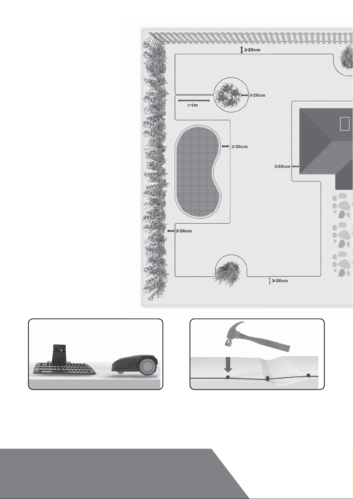
Obstacles that can be hit
When hitting any obstacle that’s rigid, stable and taller than
10cm - such as a wall or a fence - LandxcapeTM will stop and
re-direct away from the obstacle.
Stones
Stones too heavy to be moved by your LandxcapeTM can be
safely hit. However, if a stone has an inclined surface that your
LandxcapeTM can climb, it should be removed or excluded from
the working area.
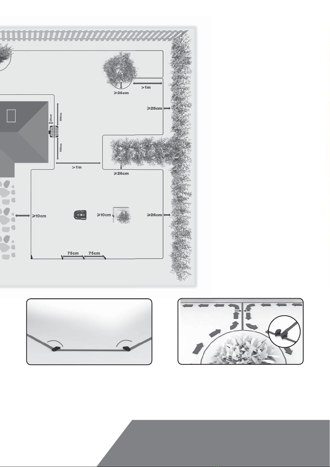
'ULYHZD\V
If your driveway is level with your lawn, without any protruding
surface, LandxcapeTM can freely run over it. If you'd like
LandxcapeTM to avoid it, place the boundary wire 10cm* away
from it.
If it’s covered with gravel, you should not allow LandxcapeTM
to travel over it. Using the distance gauge for spacing, keep a
26cm* space between the boundary wire and the driveway.
* This is the recommended distance. The provided distance
gauge ensures proper installation.
)ORZHUEHGVSRQGVSRROV
You certainly don’t want LandxcapeTM to mow your flowers, or
fall into the water. These areas should be avoided.
Additionally, obstacles between 2cm-10cm high should also be
excluded from LandxcapeTM’s operation area.