LAZER LZ11577HRB User manual

REPAIR PARTS MANUAL
MODEL NO. LZ11577HRB (96041013801)
LAWN TRACTOR
532 43 83-36 Rev. 8

2
HOW TO USE THIS MANUAL
This manual is designed to provide the customer with a means to identify the parts on his/her trac-
tor when ordering repair parts. The illustrations may or may not represent the actual assemblies;
therefore, it is not recommended to use this manual as a guide to assemble or disassemble the
tractor. Some hardware and parts are drawn larger in order to more readily identify them.
Each tractor has its own model number.
The model number for your tractor can be found on the fender under the seat.
When ordering parts, always give the following information:
• Product - “Lawn Tractor”
• Model Number - “LZ11577HRB” (96041013801)
• Part Number
• Part Description
TABLE OF CONTENTS
SCHEMATIC ...............................................................................................................3
ELECTRICAL...........................................................................................................4-5
CHASSIS AND ENCLOSURES...............................................................................6-7
DRIVE.......................................................................................................................8-9
ENGINE................................................................................................................10-11
STEERING WHEEL .................................................................................................12
SEAT ........................................................................................................................ 13
MOWER DECK ....................................................................................................14-15
DECALS ...................................................................................................................16
MOWER LIFT............................................................................................................17
BAGGER...................................................................................................................18

3
TRACTOR - - MODEL NUMBER LZ11577HRB (96041013801), PRODUCT NO. 960 41 01-38
SCHEMATIC
M
FUSE
STARTER
SOLENOID
BATTERY
REVERSE SWITCH
(NOT IN REVERSE)
SEAT SWITCH
(NOT OCCUPIED)
FULL BAG
IGNITION
UNIT
HOUR
METER
CHASSIS HARNESS
CONNECTOR (C1)
(MATING SIDE)
DASH HARNESS
CONNECTOR (C1)
(MATING SIDE)
FUEL
LINE
FUEL SHUT-OFF
SOLENOID
(IF SO EQUIPPED)
C1
S
M
B
G
L
2
3
1
6
A2
A1
M
SPARK
PLUGS GAP
(2 PLUGS ON
TWIN CYL. ENGINES)
(OPTIONAL)
NON-REMOVABLE
CONNECTIONS
REMOVABLE
CONNECTIONS
WIRING INSULATED CLIPS
NOTE: IF WIRING INSULATED
CLIPS WERE REMOVED FOR
SERVICING OF UNIT, THEY
SHOULD BE RE-INSTALLED TO
PROPERLY SECURE YOUR
WIRING.
SCH17
IGNITION SWITCH
CIRCUIT
POSITION
OFF
B+A1
RUN/OVERRIDE
B+S+A1START
M+G+A1
B+A1RUN
“MAKE”
L+A2
ATTACHMENT CLUTCH
(CLUTCH OFF)
BLACK
BLACK /WHITE
BLUE
BLUE BLACK
GREEN
BLACK
YELLOW
BLK/WHT
BLACK
BLK/WHT
D
E
R
WHITE
WHITE
GRAY
GRAY
BLACK
YELLOW
POWER OUTLET
(OPTIONAL)
12V
BLACK
BLUE
BLACK
BROWN
HEADLIGHTS
LIGHT SWITCH
ORANGE
LIGHTING SYSTEM OUTPUT
5 AMP AC @ 3600 RPM
ALTERNATOR
14 VOLTS AC MIN. @ 3600 RPM (LIGHTS OFF)
DIODE
28 VOLTS AC MIN. @ 3600 RPM
(CHARGING SYSTEM DISCONNECTED)
CHARGING SYSTEM OUTPUT
3 AMP DC @ 3600 RPM
NOTE
YOUR TRACTOR IS
EQUIPPED WITH A SPECIAL
ALTERNATOR SYSTEM.
THE LIGHTS ARE NOT
CONNECTED TO THE
BATTERY, BUT HAVE THEIR
OWN ELECTRICAL SOURCE.
BECAUSE OF THIS, THE
BRIGHTNESS OF THE LIGHTS
WILL CHANGE WITH ENGINE
SPEED. AT IDLE THE LIGHTS
WILL DIM. AS THE ENGINE
SPEED IS INCREASED, THE
LIGHTS WILL BECOME THEIR
BRIGHTEST.
CLUTCH/BRAKE
(PEDAL UP)
WHITE
GREEN
GREEN
BLUE RED
BAG PRESENT SWITCH
(BAG ATTACHED)
SHORTING CONNECTOR
BAG FULL SWITCH
(NOT FULL)
9
BUZZER
BLACK
BLACK
BLACK
BLUE BLACK
5
6
C1
4
C1
BROWN
8
C1
DER RED
1
2
3
654
98
123
456
89

4
TRACTOR-- MODELNUMBERLZ11577HRB (96041013801),PRODUCTNO.960 4101-38
ELECTRICAL
30
33
34
22
79 21
26
40
71
16
S01S
90
28
55
With Service Minder Option
4646
2
94
92
93
43
27
99
25
108
107
87
106
29

5
TRACTOR-- MODELNUMBERLZ11577HRB (96041013801),PRODUCTNO.960 4101-38
ELECTRICAL
KEY PART
NO. NO. DESCRIPTION
1 532 14 49-24 Battery
2 874 76 04-12 Bolt Hex Head 1/4-20 x 3/4
8 532 41 97-91 Box Battery
16 532 17 61-38 Switch Interlock Push-In
21 532 18 37-59 Harness Socket Light w/4152J
22 532 00 41-52 Bulb Light
25 532 41 66-94 Cable Starter
26 532 17 51-58 Fuse
27 873 51 04-00 Nut Keps Hex 1/4-20 unc
28 532 42 16-86 Cable, Ground
29 532 40 15-45 Switch, Seat
30 532 19 33-50 Switch, Ign
33 532 41 19-35 Key/Chain
34 532 11 07-12 Switch Light/Reset
40 532 42 10-02 Harness Ign. Dash
43 532 19 25-07 Solenoid
55 817 06 05-12 Screw Thdrol 5/16-18 x 3/4 TYTT
71 532 42 94-12 Harness Ign. Chassis
79 532 17 52-42 Socket Asm. Bulb
87 532 42 10-60 Switch Railmount NO-NC-NC
90 532 43 53-95 Cover Terminal
92 532 19 66-15 Harness Pigtail Console ROS
93 532 19 25-40 Screw Plastite 10-14 x 2.0
94 532 19 18-34 Module Reverse
99 817 67 04-12 Screw 1/4-20 x 3/4
106 532 17 48-14 Palnut 1/4 Lugs
107 532 42 10-61 Switch Snapmount No #2
108 532 42 10-62 Switch Snapmount NC
NOTE: All component dimensions given in U.S. inches
1 inch = 25.4 mm

6
TRACTOR-- MODELNUMBERLZ11577HRB (96041013801),PRODUCTNO.960 4101-38
CHASSIS
68
68
68
68
183
183
236
236 34
235
235
177
175
176
176
182
176
176
5
52
217
189
189
152
68
68
213
218
228
228
194
180
58
189
189
chassis-tex_elite basic_8
282
162
287
162
308
159
309
159
159
311
284
310
283
199
282
37
282
194
194
36
36
130
151
150
137
14
18
153
302
319

7
TRACTOR-- MODELNUMBERLZ11577HRB (96041013801),PRODUCTNO.960 4101-38
CHASSIS
NOTE: All component dimensions given in U.S. inches
1 inch = 25.4 mm
KEY PART
NO. NO. DESCRIPTION
5 532 41 17-64 Dash
14 532 18 67-07 Hood
18 532 42 67-92 Grille
34 532 19 61-25 Plate Engine
36 817 06 05-12 Screw 5/16-18 x 3/4
37 532 44 13-39 Fender
52 873 68 05-00 Nut Crown Lock 5/16
58 532 41 22-80 Drawbar Upper
68 817 49 05-08 Screw Thdrol. 5/16-18 x 1/2
130 532 41 63-58 Screw #10 x 0.750 BOS Thread
137 532 18 49-21 Bumper Dash
150 532 18 44-61 Duct Intake Air
151 532 40 78-07 Bracket Pivot
152 532 19 95-35 Shield Browning
153 532 18 98-37 Lens Grille
159 817 00 06-12 Screw Kexwsh Thdr 3/8-16 x 3/4
162 532 14 24-32 Screw Hex Wsh. Hi-Lo 1/4 x 1/2 unc
175 532 19 32-43 Crossmember
176 532 40 07-76 Screw 10-24 x 5/8
177 532 19 52-28 Bushing Steering
180 532 41 46-85 Chassis
182 532 19 30-57 Dash Lower
183 874 52 05-20 Bolt 5/16-18 x 1-1/4 Full Thd
189 817 00 05-12 Screw 5/16-18 x 3/4
194 873 90 05-00 Nut Lock Hex Flange 5/16-18
199 532 41 87-39 Plate Deck Lift
213 874 76 05-12 Bolt 5/16-18 x 3/4
217 532 40 91-67 Rod Pivot Hood
218 532 19 63-95 X-Piece Hood Stop
228 532 19 51-61 Stud Fastener
235 532 40 61-29 Spacer Fender
236 873 93 05-00 Nut Lock 5/16-18 unc
282 532 41 41-10 Clip Retainer
283 532 44 03-61 Console Deck Lift
284 532 42 59-45 Console Shift
287 817 60 04-06 Screw Hex Washead 1/4-20 x 3/8
302 532 18 38-23 Insert Lens Refl
308 532 17 18-77 Bolt 5/16-18 unc x 3/4
309 532 43 02-46 Backplate Bagger SRD
310 532 44 66-36 Bracket Hangar Bag LH
311 532 44 66-37 Bracket Hangar Bag RH
319 532 17 46-62 Bracket Actuator

8
TRACTOR-- MODELNUMBERLZ11577HRB (96041013801),PRODUCTNO.960 4101-38
DRIVE
56
165
166
64
188
161
35
184
221
167160
42
159
185
29
15
159
17
drive-tex_T2_fender_17_r2
263
275
268
216
143
185
51
231
170
186
189
49
187
50
51
52
51
190
279
116
2
183
205
205 37
33
1
2
99
73
73
116
114
122
121
80
125
125
23
174
288
233
232
22
176
178
166
166
232
292
175
289
125
125
153
153
290
289
153
153

9
TRACTOR-- MODELNUMBERLZ11577HRB (96041013801),PRODUCTNO.960 4101-38
DRIVE
KEY PART
NO. NO. DESCRIPTION
KEY PART
NO. NO. DESCRIPTION
1 - - - - - - - - - Transaxle, Hydro T2-BABC-1X1A-
1GX1 (Internal Parts Not Available)
2 532 12 35-83 Key
15 819 13 13-16 Washer 13/32 x 13/16 x 16 Ga.
17 532 19 72-96 Spring, Brake
22 532 41 66-14 Rod Shift
23 532 12 12-74 Knob
29 532 42 32-39 Rod, Brake
33 812 00 00-01 Ring E
35 532 19 77-22 Rod, Brake, Park
37 532 12 17-49 Washer 25/32 x 1-1/4 x 16 Ga.
42 532 12 48-72 Cover, Foot Pedal
49 872 11 06-14 Bolt
50 532 19 43-27 Pulley Idler Flat
51 873 90 06-00 Lock Nut 3/8-16
52 532 19 43-26 Idler V-Groove 910" Offset
56 532 12 59-07 V-Belt, Drive
64 532 19 62-00 Shaft Asm. Pedal Brake Control
73 874 49 05-44 Bolt Hex Flghd 5/16-18 Gr. 5
80 581 55 07-01 Strap Torque
99 532 40 84-18 Rod Asm. Bypass
114 873 80 05-00 Nut Lock Hex w/INS 5/16-18 unc
116 873 90 05-00 Nut Lock Hex Flange 5/16-18
121 532 17 56-11 Bracket Strap Torque
122 872 01 05-20 Bolt 5/16-18 x 2.50
125 817 00 05-12 Screw 5/16-18 x 3/4
143 817 49 05-08 Screw 5/16-18 x 1/2
153 532 12 47-88 Retainer Spring 1"
159 876 02 04-12 Pin Cotter 1/8 x 3/4
160 532 16 94-84 Retainer Clip
161 532 10 57-09 Spring, Return, Clutch
165 532 19 62-12 Bushing
166 532 42 91-64 Nut Push .625
167 532 40 52-57 Latch Brake Parking
170 532 41 34-30 Keeper Belt Centerspan
174 532 19 72-89 Nut Push
175 532 40 85-39 Shaft Asm
176 532 19 62-14 Asm Clevis Rod Shift
178 532 19 63-14 Spring Shift
183 532 15 69-72 Spacer Axle
184 532 41 12-89 Handle Parking Brake
185 872 11 06-22 Bolt
186 532 19 43-21 Spacer Retainer
187 819 13 32-10 Washer
188 532 19 43-23 Link Clutch Ground Drive
189 532 19 43-17 Bellcrank Ground Drive
190 532 19 43-18 Keeper Bellcrank Ground Drive
205 532 12 17-48 Washer 25/32 x 1-5/8 x 16 Ga.
216 532 19 61-31 Bracket Pulley Idler
221 532 40 31-87 Retainer Spring Clip Handle
231 532 40 72-87 Idler V-Groove 1.688 Offset
232 874 78 07-16 Bolt Fin Hex 7/16-14 x 1
233 532 40 52-96 Washer Serrated
263 817 00 06-12 Screw Hex Wsh Thdrol 3/8-16 x 3/4
268 819 13 16-14 Washer 13/32 x 1 x 14
275 532 18 24-02 Guard Muffler
279 532 42 41-55 Link Shift
288 532 41 66-17 Link Shift Slave
289 532 41 75-20 Bracket Support
290 532 42 00-14 Shaft Asm. Shift Rear
292 532 41 93-07 Plate Asm. Shift FWD
NOTE: All component dimensions given in U.S. inches
1 inch = 25.4 mm
10
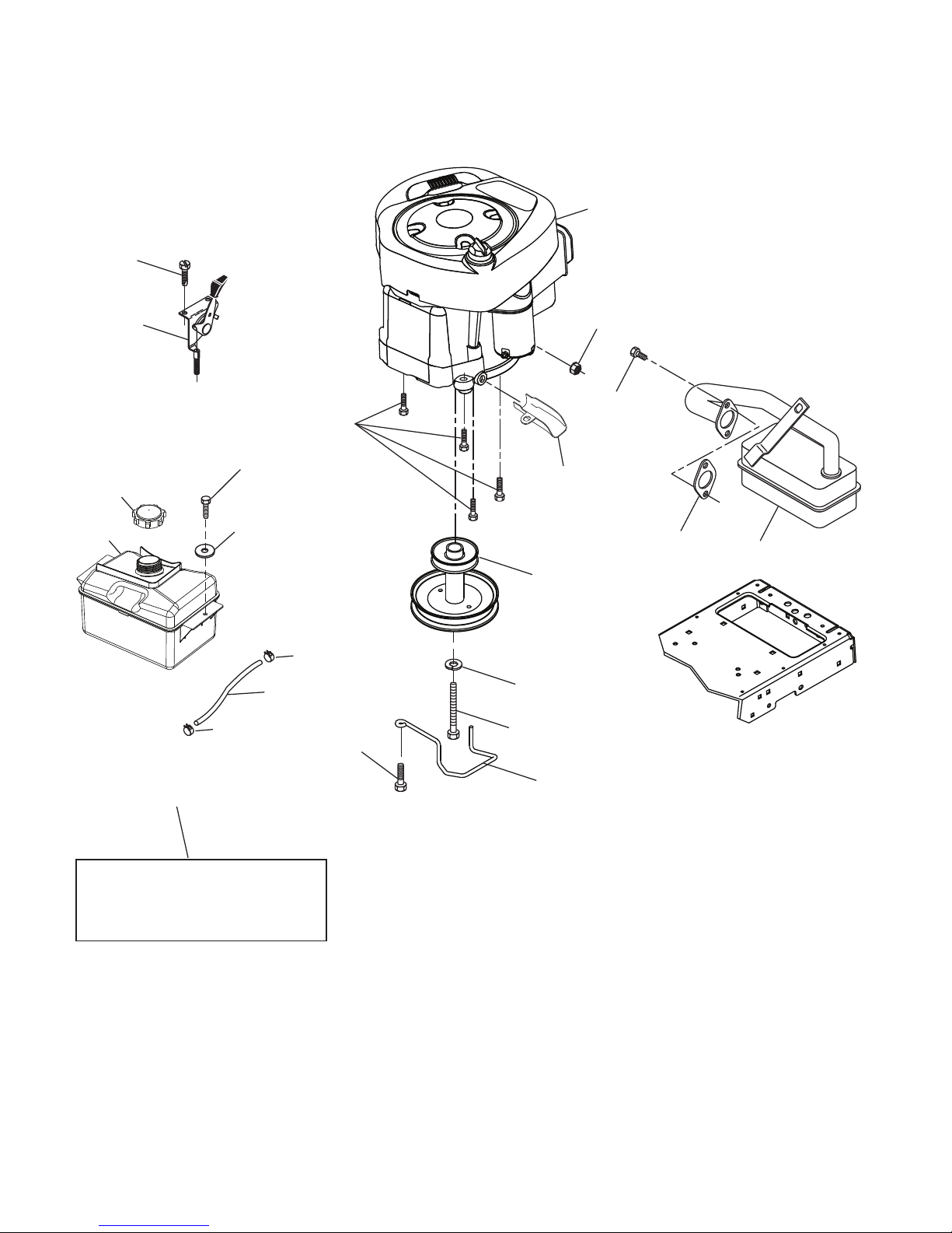
TRACTOR-- MODELNUMBERLZ11577HRB (96041013801),PRODUCTNO.960 4101-38
ENGINE
21
20
OPTIONAL EQUIPMENT
Spark Arrester
29
18
15
37
28
engine-tex_BS_36
12
42
85
9
90
84
45
1
122
69 2
79
97
96
37

11
KEY PART
NO. NO. DESCRIPTION
1 532 43 86-13 Engine BS Model No. 217807-3209-B1
2 532 17 97-58 Muffler
9 532 19 43-19 Keeper Belt Engine
12 532 14 01-86 Pulley Engine
15 532 40 75-45 Tank Fuel 1.5
18 532 43 02-20 Cap Asm
20 532 18 38-97 Control Throttle
21 532 41 63-58 Screw #10 x 0.750 BOS Thread
28 532 13 70-40 Fuel Line
29 532 13 71-80 Spark Arrester Kit
37 532 12 34-87 Clamp Hose
42 810 04 07-00 Washer Lock Hvy HLCL SPR 7/16
45 873 51 04-00 Nut Keps Hex 1/4-20 unc
69 532 16 52-91 Gasket
79 532 19 23-34 Screw Socket HD 5/16 - 18 x 75
84 817 06 06-20 Screw 3/8-16 x 1-1/4
85 532 17 39-37 Bolt Hex 7/16-20 x 4 Gr. 5
90 817 00 06-16 Screw 3/8-16 x 1
96 819 09 14-16 Washer 9/32 x 7/8 x 16 Ga.
97 817 67 04-12 Screw 1/4-20 x 3/4
122 532 42 19-22 Extension Oil Drain
Engine Power Rating Information
The gross power rating for individual gas engine models is labeled in accordance with SAE (Society of Automotive Engi-
neers) code J1940 (Small Engine Power & Torque Rating Procedure), and rating performance has been obtained and cor-
rected in accordance with SAE J1995 (Revision 2002-05). Torque values are derived at 3060 RPM; horsepower values are
derived at 3600 RPM. Actual gross engine power will be lower and is affected by, among other things, ambient operating
conditions and engine-to-engine variability. Given both the wide array of products on which engines are placed and the va-
riety of environmental issues applicable to operating the equipment, the gas engine will not develop the rated gross power
when used in a given piece of power equipment (actual “on-site” or net power). This difference is due to a variety of factors
including, but not limited to, accessories (air cleaner, exhaust, charging, cooling, carburetor, fuel pump, etc.), application
limitations, ambient operating conditions (temperature, humidity, altitude), and engine-to-engine variability. Due to manu-
facturing and capacity limitations, Briggs & Stratton may substitute an engine of higher rated power for this Series engine.
TRACTOR-- MODELNUMBERLZ11577HRB (96041013801),PRODUCTNO.960 4101-38
ENGINE
NOTE: All component dimensions given in U.S. inches
1 inch = 25.4 mm
12
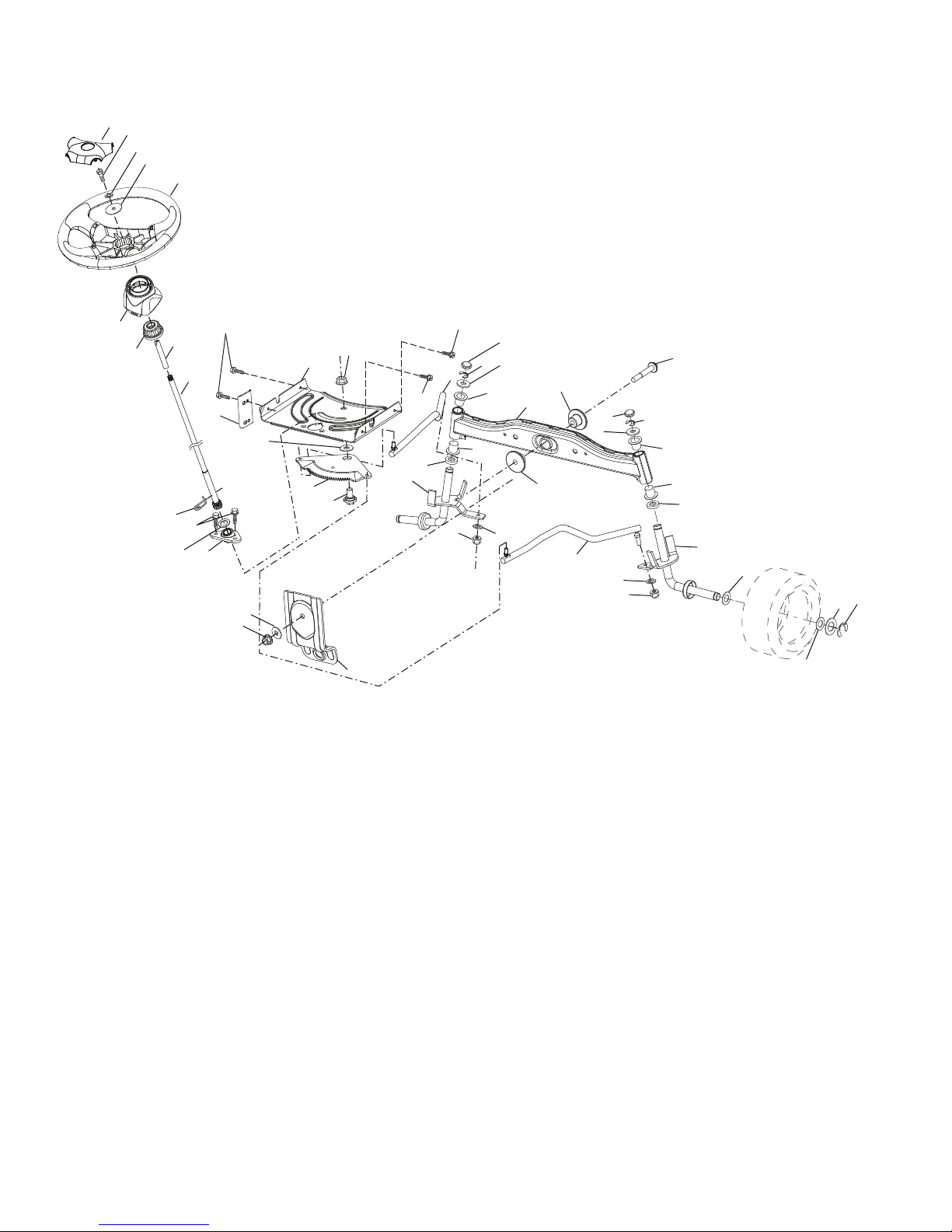
TRACTOR-- MODELNUMBERLZ11577HRB (96041013801),PRODUCTNO.960 4101-38
STEERING ASSEMBLY
5
13
13
53 8
62
4
35
59
58
70
68
69
15
15
14
14
61
steering-tex_STDHRS_6
16
71
28
13 22
64
21
26
1
20
45
33
72
19
60
63
57
63
63
67
67
66
9
9
8
8
7
7
2
6
6
74
74
74
74
KEY PART
NO. NO. DESCRIPTION
NOTE: All component dimensions given in U.S. inches
1 inch = 25.4 mm
KEY PART
NO. NO. DESCRIPTION
1 532 42 45-43 Wheel, Steering
2 532 41 81-68 Axle Asm., Front
4 532 41 68-45 Spindle Asm., LH
5 532 41 68-46 Spindle Asm., RH
6 532 12 49-31 Bearing, Race Thrust Hardened
7 532 12 17-48 Washer 25/32 x 1-5/8 x 16 Ga.
8 812 00 00-29 Ring, Klip #T5304-75
9 532 12 12-32 Cap, Spindle
13 532 12 17-49 Washer, 25/32 x 1-1/4 x 16 Ga.
14 810 04 06-00 Washer, Lock Hvy Hlcl Spr 3/8
15 873 54 06-00 Nut, Crown Lock 3/8-24 unf
16 532 42 93-73 Shaft Steering
19 532 19 47-29 Plate Steering
20 532 41 12-91 Boot, Steering
21 532 18 67-37 Adapter, Wheel Steering
22 532 42 05-37 Steering Supt. Lower
26 532 42 46-91 Insert, Wheel Steering
28 817 00 06-12 Screw 3/8-16 x 3/4
33 810 04 05-00 Washer Lock 5/16
35 532 19 47-32 Gear, Sector Plate
45 819 11 38-12 Washer 11/32 x 3/8 x 12 Ga.
53 532 18 89-67 Washer Hardened .793 x 1.637 x
.060
57 532 40 74-65 Bracket Upstop
58 532 19 47-47 Bolt Shoulder Sector Pivot CFM
59 532 19 47-48 Washer Thrust Sector Steering
60 873 97 10-00 Nut Flange Lock 5/8-11
61 532 19 47-40 Draglink, LH
62 532 19 47-41 Draglink, RH
63 817 00 05-12 Screw 5/16-18 x 3/4
64 532 19 98-49 Retainer Clip Spring Steering
66 871 02 07-48 Bolt Hex Fghd 7/16-14 x 3 Serr
67 532 19 47-37 Bushing PM Front Axle
68 873 90 07-00 Nut Lock Flange 7/16-14 Gr. 5
69 532 19 91-62 Washer 1.5 x .505 x .118
70 532 41 70-65 Bracket Deck Susp. Front
71 532 19 60-75 Shaft Extension Steering
72 532 42 89-82 Bolt Fin. Hx. 5/16-18 x 4 w/patch
74 532 12 49-37 Bearing
13
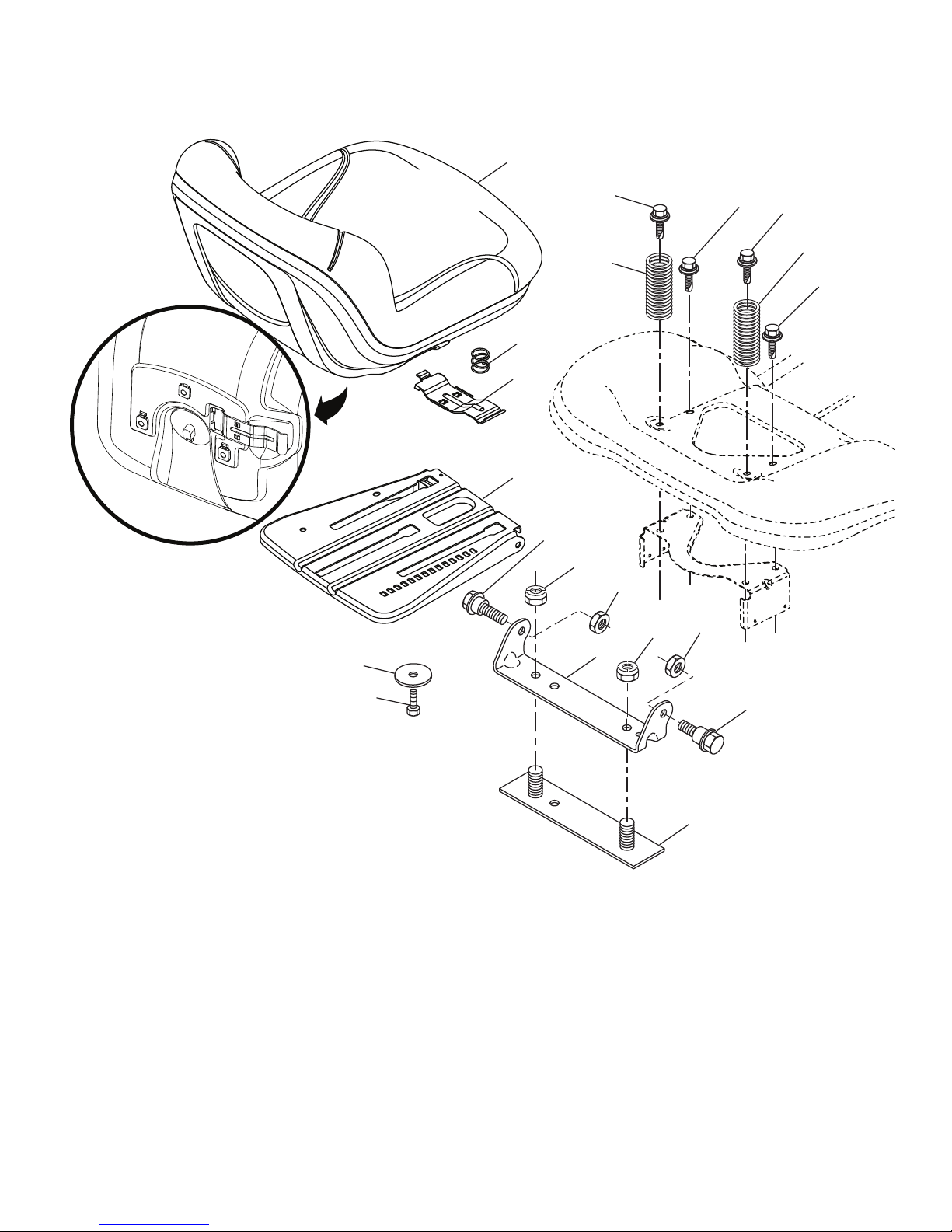
TRACTOR - - MODEL NUMBER LZ11577HRB (96041013801), PRODUCT NO. 960 41 01-38
SEAT ASSEMBLY
2
6
1
40
10
37
37
21
21
3
41
7
8
7
8
seat-tex_7A-vgt
44
43
8
8
6
1 532 19 75-11 Seat
2 532 18 01-66 Bracket Pivot Fender
3 532 14 06-75 Strap, Asm Fender
6 873 80 06-00 Nut, Lock w/Ins. 3/8-16 unc
7 532 12 41-81 Spring, Seat Cprsn
8 532 17 18-77 Bolt 5/16-18 unc x 3/4 w/Sems
10 532 19 69-77 Pan, Seat
21 532 17 18-52 Bolt, Shoulder 5/16-18
37 873 80 05-00 Nut, Lock 5/16-18 unc
40 532 19 76-61 Handle Slide Seat
41 532 19 82-00 Spring Latch Seat
43 874 76 06-12 Bolt 3/8-16 x 3/4
44 819 13 38-12 Washer 13/32 x 2-3/8 x 12 Ga.
KEY PART
NO. NO. DESCRIPTION
KEY PART
NO. NO. DESCRIPTION
NOTE: All component dimensions given in U.S. inches
1 inch = 25.4 mm
14
70
7
7
37
67
152
TRACTOR-- MODELNUMBERLZ11577HRB (96041013801),PRODUCTNO.960 4101-38
MOWER DECK
6
38
2
4
3
33
34
35
36
38
26
1
5
17
43
18
19
20
21
25
24
22
23
20
32
9
10 11
12
14
15
16
13
8
tex-deck_SRD_4_r5
27
40
42
42
41
73
42
42
29
74
72
26
11
76

15
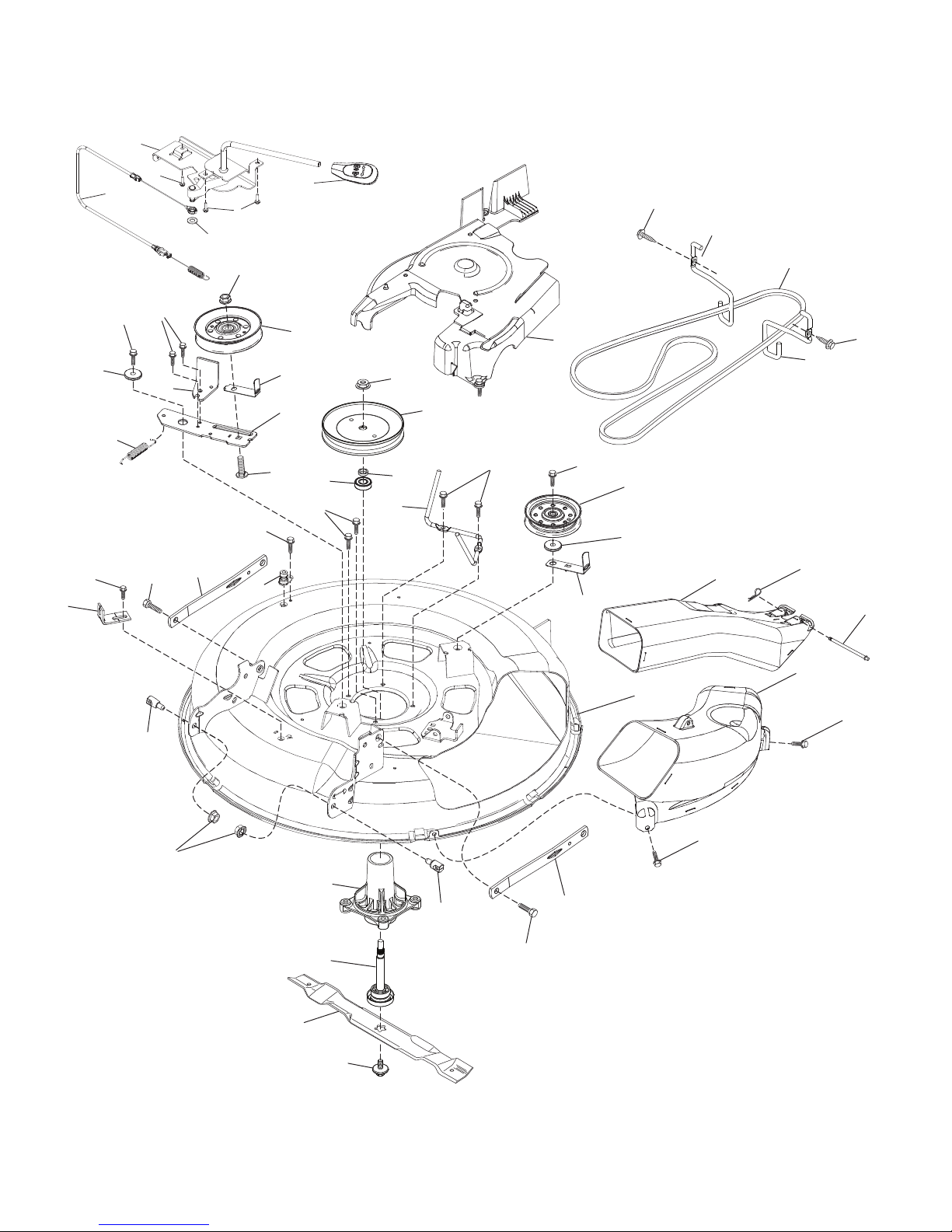
TRACTOR-- MODELNUMBERLZ11577HRB (96041013801),PRODUCTNO.960 4101-38
MOWER DECK
KEY PART
NO. NO. DESCRIPTION
NOTE: All component dimensions given in U.S. inches
1 inch = 25.4 mm
1 532 41 92-72 Deck Weldment 30" Srd
2 532 19 51-61 Stud Fastner w/'D'anti-Rotatio
3 873 90 05-00 Nut Lock Hex Flange 5/16-18
4 532 41 76-45 Bracket Clutch Cable
5 817 00 05-10 Bolt 5/16-18
6 532 41 88-63 Arm Susp Mower Rear Srd
7 532 41 63-58 Screw #10 x 0.750 BOS Thread
8 532 42 02-52 Arm Idler 30"Srd
9 532 19 90-92 Spacer Retainer
10 817 00 06-16 Screw 3/8-16 X 1 Smgml Tap/R Blk
11 532 13 77-29 Screw Thd Roll 1/4-20 X 5/8
12 532 19 94-70 Arm Brake Mower 38" RH Tex
13 872 11 06-12 Bolt Carr Sh 3/8-16 X 1-1/2 Gr. 5
14 532 15 60-85 Keeper Belt Idler
15 532 14 67-63 Pulley Idler V-Groove Dim 4.25
16 873 90 06-00 Nut Lock FlG 3/8-16 unc
17 532 40 02-34 Nut Flange Lock Top
18 532 18 76-90 Washer Spacer Mandrel
19 532 11 04-85 Bearing Ball Mandrel
20 532 17 39-84 Screw Thd Roll Dod Pt Hex
21 532 41 69-10 Keeper Belt Mandrel 30"
22 532 19 31-98 Pulley Idler Flat Unplated
23 817 49 06-28 Screw Thdrol 3/8-16 X 1-3/4
24 819 13 20-12 Washer 13/32 X 1-1/4 X 12 Ga
25 532 42 02-53 Keeper Belt 30" Srd
26 532 43 03-13 Cover Mandrel Mwr 30" Black
27 532 41 92-71 V-Belt Drive
29 532 42 08-95 Hinge Pin
32 532 40 18-72 Spring Return Deck 38/46"
33 532 18 72-81 Housing Mandrel 4pt Service
34 532 19 28-72 Shaft Asm Mndrl N/Greaseable38
35 532 41 92-74 Blade Mower Bagging Srd
36 532 19 30-03 Bolt/Washer Asm 7/16-20 unf
37 819 13 13-16 Washer 13/32 x 13/16 x 16 Ga.
38 532 19 65-39 Bolt Shoulder
40 532 41 92-70 Keeper Belt Engine LH
41 532 41 92-65 Keeper Belt Engine RH
42 817 00 06-12 Screw Hexwsh THDR 3/8-16 x 3/4 BL
43 532 41 68-77 Pulley Mandrel 6 5 Pd 30"
67 532 40 30-12 Handle Clutch Cable
70 532 19 83-32 Clutch Asm. Manual
72 532 41 72-36 Chute Upper SRD 30R
73 532 42 52-74 Chute Lower SRD 30R
74 532 12 46-70 Retainer Spring
76 532 41 55-98 Port Washout
152 532 43 51-11 Manual Clutch Cable
- - 532 19 28-70 Mandrel Assembly (Includes Housing,
Shaft Assembly, And Bearing Only - Pul-
ley/Nut/Washer And Blade Bolt/Washers
Not Included)
- - 532 42 16-06 Replacement Mower Complete

16
TRACTOR-- MODELNUMBERLZ11577HRB (96041013801),PRODUCTNO.960 4101-38
DECALS
6
2
1
3
11
4
10
5
9
8
7
wheel_art_1-tex
WHEELS AND TIRES
KEY PART
NO. NO. DESCRIPTION
11
9
1 532 40 03-89 Decal, Operators
2 532 43 82-64 Decal, Hood Logo
3 532 19 68-41 Decal, Warning Eng. Symbols
5 532 15 97-36 Decal, Chassis Hot Muffler
6 532 18 04-32 Decal, Fender 100 DB/CE
7 532 43 35-14 Decal, Wheel Steering
9 532 14 50-05 Decal, Battery Dnge/Poi
10 532 14 08-37 Decal, Saddle Brake Parking
11 532 42 51-13 Decal, Warning DFlect/Ctfingr
12
1
2
7
1
2
5
6
10
13
3
5
KEY PART
NO. NO. DESCRIPTION
12 532 42 15-43 Decal, Mower V-Belt Schematic
13 532 15 97-37 Decal, Brake/Clutch Symbol
17 532 43 74-09 Decal, BS Engine
- - 532 16 69-60 Decal, Bypass Fender
- - 532 42 59-76 Pad, Footrest, LH
- - 532 42 59-28 Pad, Footrest, RH
- - 532 43 88-11 Manual Oper. Euro
- - 532 43 88-13 Manual Oper. Scand
NOTE: All component dimensions given in U.S. inches
1 inch = 25.4 mm
KEY PART
NO. NO. DESCRIPTION
1 532 05 91-92 Cap Valve Tire
2 532 06 51-39 Stem Valve
3 532 42 67-59 Rim Asm 6 x 3.25 Front
4 532 42 16-52 TubeFront13x5-6(ServiceItemOnly)
5 532 44 22-86 Tire F T 13 x 5.0 - 6
6 532 12 49-57 Fitting Grease (Front Wheel Only)
7 532 12 49-59 Bearing Flange (Front Wheel Only)
8 532 17 50-39 Cap Axle Blk 1 50 x 1 00
9 532 44 22-87 Tire R 16 x 6.5
10 532 00 71-54 Tube Rear (Service Item Only)
11 532 42 67-60 Rim Asm 8 x 5.375 Rear
- - 532 14 43-34 Sealant, Tire (10 oz. Tube)
17
17
TRACTOR-- MODELNUMBERLZ11577HRB (96041013801),PRODUCTNO.960 4101-38
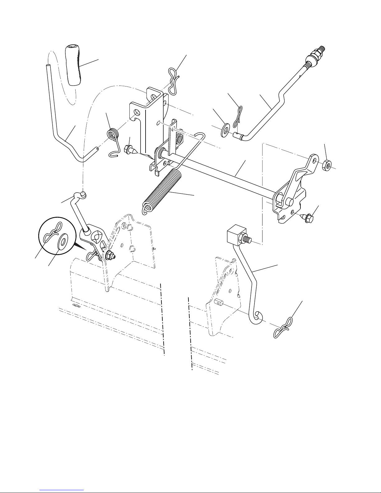
MOWER LIFT
lift-tex_17_r1 *Key 91 may be substituted for Key 101
2 532 42 20-27 Shaft Asm., Lift
3 532 19 52-31 Lever Asm., Lift RH
7 532 41 15-55 Grip, Lever
10 532 19 63-14 Spring Torsion
87 532 19 42-09 Pin Cotter 7/16 Bow Tie Lock
88 532 41 07-10 Spring Lift Assist
89 819 19 19-12 Washer Clear
90 532 19 42-08 Pin Cotter 5/16 Bow Tie Lock
91 532 19 51-81 Link Lift Susp Mower Rear
KEY PART
NO. NO. DESCRIPTION
NOTE: All component dimensions given in U.S. inches
1 inch = 25.4 mm
97 817 00 06-12 Screw 3/8-16 x 3/4
98 532 19 52-64 Link Lift Susp. Front Mower
100 873 93 06-00 Nut Centerlock 3/8-16
101 532 40 70-03 Link Asm Lift Fxd
113 819 17 19-12 Washer 17/32 x 1-3/16 x 12 Ga.
KEY PART
NO. NO. DESCRIPTION

18
TRACTOR-- MODELNUMBERLZ11577HRB (96041013801),PRODUCTNO.960 4101-38
BAGGER
25
25
26
7
14
20
14
23
10
20
17
12
18
26
14
22
SRD_BAGGER_11_r1
7
23
8
4
12
11
7
11
16
22
14
21 12
7
1
19
6
28
23
27
7
7
23
13
9
5
1 532 42 86-10 Tube Handle Bagger SRD
4 532 43 96-12 Frame Asm Bagger Top
5 532 41 76-32 Frame Asm Top Bagger SRD
6 532 12 68-75 Drilled Rivit
7 873 90 04-00 Nut Hex Flange 1/4-20 unc
8 532 42 59-54 Cover Bagger SRD
9 532 41 76-29 Insert Handle Bagger
10 532 41 71-90 Frame Front
11 532 41 71-88 Tubing Brace Bagger
12 532 42 17-93 Nut Square 1/4
13 532 42 17-80 Screw 1/4 x 1.150 HXWSH
14 532 42 18-00 Bolt Shoulder HX WSH 1/4 x 1.150
16 532 42 15-66 Deflector Bagger
17 532 42 17-49 Lever Bagger Full
KEY PART
NO. NO. DESCRIPTION
KEY PART
NO. NO. DESCRIPTION
NOTE: All component dimensions given in U.S. inches
1 inch = 25.4 mm
18 532 42 17-50 Paddle Bagger Full
19 532 19 42-08 Pin Cotter 5/16
20 585 36 88-01 Screw Hex Cap 1/4-20 x 1.375
21 532 42 99-83 Bag Asm SRD
22 532 14 24-32 Screw Hex WSH Hi-Lo 1/4 - 1/2 unc
23 872 04 04-10 Bolt Carr 1/4-20 unc x 1-1/4
25 532 42 16-14 Spring Latch Bagger
26 817 49 04-12 Screw Hex Thdrol 1/4-20 x 3/4
27 532 42 12-62 Grommet, Rubber SRD
28 532 16 57-87 Grip Handle Black

19
SERVICE NOTES

09.16.13 BD/TH Printed in the U.S.A.
Other manuals for LZ11577HRB
1
Table of contents
Other LAZER Lawn Mower manuals


