3. MENU SETTING
Before setting the functions, please make sure the device is connected
correctly.
3-1. Shortcut keys:
3-1-1. the image menu
Dialing to the left or right when power on, brightness will appear at the bottom
of the screen, then press the dial to switch among of brightness, sharpness,
contrast, saturation, volume, tint, MENU and Exit. User can adjust the value
of the selected option via the dial.
3-1-2. F1-F2 2 user-definable function buttons:
Long press any F1-F2 key for 3-5 seconds to pop-up
shortcut menu directly. As shown in Figure (default menu
button in white font).
Select option via dialing to the left or right.
Press to confirm option as default, then press EXIT to exit.
Functions of F1-F2 buttons can also be customized: Center
Marker, Aspect Marker, Check Field, Underscan, Scan,
Aspect, DSLR, Freeze, H/V delay, Peaking, False Color,
Exposure, Histogram, Level Meter, Waveform and Time
Code.
Note: Time code is only available under SDI mode.
F1-F2:2 user-definable function buttons
Default function:
F1 Waveform F2 Scan
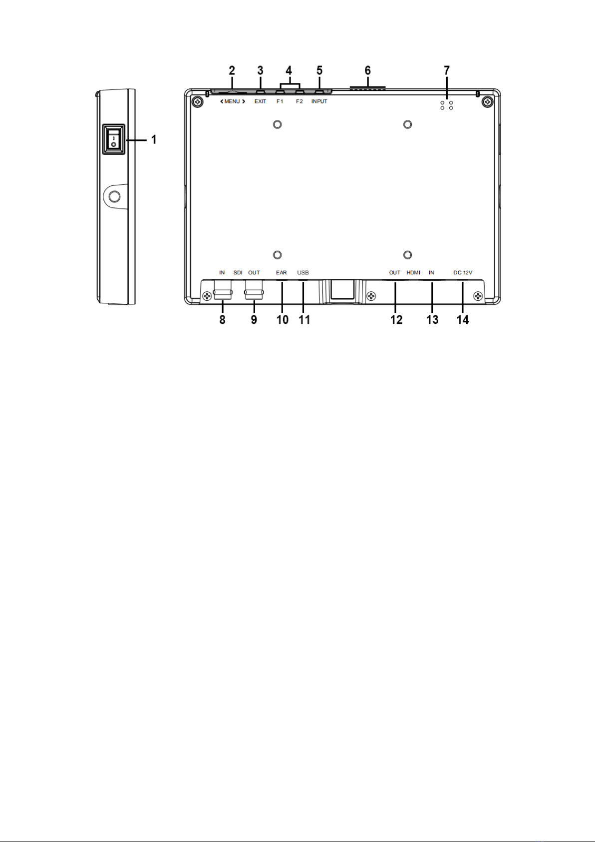
3-2. MENU Operation
When power on, press “MENU” on the device. The menu of function setting
will display on the screen.
Dialing left or right to choose menu, and press to confirm, and then press EXIT
to return.