Macrom CAR AUDIO EQUIPMENT 45.40 User manual

45.40
Owner`s Manual
Bedienungsanleitung
Manuel d`Emploi
Manuale di Instruzioni
Manual de Instrucciones
CAR AUDIO EQUIPMENT ®
O/M 45.40 (5T) 25/06/02 19:25 Page 1

I
Contents / Inhalt / Table de Matieres / Indice / Ìndice
•Connections / Anschlusse / Connexiones / Collegamenti / Conexiones . . . . . . . . . . . . . . . . II
• System Chart / System-Diagramm / Exemples de Systeme /
Diagramma di Sistema / Diagrama del Sistema. . . . . . . . . . . . . . . . . . . . . . . . . . . . . . . . . . III
“ ENGLISH”
INTRODUCTION . . . . . . . . . . . . . . . . . . . . . . . . . . . . . . . . . . . . . . . . . . . . . . . . . . . . . . . . . . . 7
PRECAUTIONS . . . . . . . . . . . . . . . . . . . . . . . . . . . . . . . . . . . . . . . . . . . . . . . . . . . . . . . . . . . . 7
FEATURES. . . . . . . . . . . . . . . . . . . . . . . . . . . . . . . . . . . . . . . . . . . . . . . . . . . . . . . . . . . . . . . . 7
CONTROL AND INICATORS . . . . . . . . . . . . . . . . . . . . . . . . . . . . . . . . . . . . . . . . . . . . . . . . . . 8
CONTROL AND INICATORS . . . . . . . . . . . . . . . . . . . . . . . . . . . . . . . . . . . . . . . . . . . . . . . . . . 9
TECHNICAL DATA . . . . . . . . . . . . . . . . . . . . . . . . . . . . . . . . . . . . . . . . . . . . . . . . . . . . . . . . . 10
THEORY OF OPERATION . . . . . . . . . . . . . . . . . . . . . . . . . . . . . . . . . . . . . . . . . . . . . . . . . . . 11
“ DEUTSCH ”
INTRODUCTION . . . . . . . . . . . . . . . . . . . . . . . . . . . . . . . . . . . . . . . . . . . . . . . . . . . . . . . . . . 12
PRECAUTIONS . . . . . . . . . . . . . . . . . . . . . . . . . . . . . . . . . . . . . . . . . . . . . . . . . . . . . . . . . . . 12
EIGENSCHAFTEN . . . . . . . . . . . . . . . . . . . . . . . . . . . . . . . . . . . . . . . . . . . . . . . . . . . . . . . . . 12
EINSTELLUNGEN UND ANZEIGEN . . . . . . . . . . . . . . . . . . . . . . . . . . . . . . . . . . . . . . . . . . . 13
EINSTELLUNGEN UND ANZEIGEN . . . . . . . . . . . . . . . . . . . . . . . . . . . . . . . . . . . . . . . . . . . 14
TECHNISCHE DATEN . . . . . . . . . . . . . . . . . . . . . . . . . . . . . . . . . . . . . . . . . . . . . . . . . . . . . . 15
FUNKTIONSPRINZIP. . . . . . . . . . . . . . . . . . . . . . . . . . . . . . . . . . . . . . . . . . . . . . . . . . . . . . . 16
“ FRANCAIS ”
INTRODUCTION . . . . . . . . . . . . . . . . . . . . . . . . . . . . . . . . . . . . . . . . . . . . . . . . . . . . . . . . . . 17
PRECAUTIONS . . . . . . . . . . . . . . . . . . . . . . . . . . . . . . . . . . . . . . . . . . . . . . . . . . . . . . . . . . . 17
CARACTERISTIQUES . . . . . . . . . . . . . . . . . . . . . . . . . . . . . . . . . . . . . . . . . . . . . . . . . . . . . . 17
CONTROLES ET INDICATEURS. . . . . . . . . . . . . . . . . . . . . . . . . . . . . . . . . . . . . . . . . . . . . . 18
CONTROLES ET INDICATEURS. . . . . . . . . . . . . . . . . . . . . . . . . . . . . . . . . . . . . . . . . . . . . . 19
DONNEES TECHNIQUES . . . . . . . . . . . . . . . . . . . . . . . . . . . . . . . . . . . . . . . . . . . . . . . . . . . 20
PRINCIPE DE FONCTIONNEMENT . . . . . . . . . . . . . . . . . . . . . . . . . . . . . . . . . . . . . . . . . . . 21
“ ITALIANO ”
INTRODUZIONE . . . . . . . . . . . . . . . . . . . . . . . . . . . . . . . . . . . . . . . . . . . . . . . . . . . . . . . . . . 22
PRECAUZIONI . . . . . . . . . . . . . . . . . . . . . . . . . . . . . . . . . . . . . . . . . . . . . . . . . . . . . . . . . . . . 22
CARATTERISTICHE . . . . . . . . . . . . . . . . . . . . . . . . . . . . . . . . . . . . . . . . . . . . . . . . . . . . . . . 22
CONTROLLI & INDICATORI . . . . . . . . . . . . . . . . . . . . . . . . . . . . . . . . . . . . . . . . . . . . . . . . . 23
CONTROLLI & INDICATORI . . . . . . . . . . . . . . . . . . . . . . . . . . . . . . . . . . . . . . . . . . . . . . . . . 24
DATI TECNICI . . . . . . . . . . . . . . . . . . . . . . . . . . . . . . . . . . . . . . . . . . . . . . . . . . . . . . . . . . . . 25
TEORIA DEL FUNZIONAMENTO . . . . . . . . . . . . . . . . . . . . . . . . . . . . . . . . . . . . . . . . . . . . . 26
“ ESPAÑOL ”
INTRODUCTION . . . . . . . . . . . . . . . . . . . . . . . . . . . . . . . . . . . . . . . . . . . . . . . . . . . . . . . . . . 27
PRECAUTIONS . . . . . . . . . . . . . . . . . . . . . . . . . . . . . . . . . . . . . . . . . . . . . . . . . . . . . . . . . . . 27
CARACTERÍSTICAS . . . . . . . . . . . . . . . . . . . . . . . . . . . . . . . . . . . . . . . . . . . . . . . . . . . . . . . 27
CONTROLES & INDICADORES . . . . . . . . . . . . . . . . . . . . . . . . . . . . . . . . . . . . . . . . . . . . . . 28
CONTROLES & INDICADORES . . . . . . . . . . . . . . . . . . . . . . . . . . . . . . . . . . . . . . . . . . . . . . 29
DATOS TÉCNICOS . . . . . . . . . . . . . . . . . . . . . . . . . . . . . . . . . . . . . . . . . . . . . . . . . . . . . . . . 30
TEORIA DE FUNCIONAMIENTO. . . . . . . . . . . . . . . . . . . . . . . . . . . . . . . . . . . . . . . . . . . . . . 31
O/M 45.40 (5T) 25/06/02 19:25 Page 2

II
1 2 3 4 5 6 7 8 9 10
Rear SubFrontInput
L
R
2 Ch 4Ch
Gain
Control
4V 0,2V
Flat 63 80Hz Flat 63 80Hz 50 80 120Hz
L
RWave
Alignement
Min. Max.
Mode
Gain
Control
4V 0,2V
Gain
Control
4V 0,2V
Front/Sub Rear
11 12 13 14 15
45.40 5 Channel Power Amplifier
Power Speaker Connector
+
-
Sub L/F R/F
ChecK Control
L/R R/R
Check Control
Power Connector
+ Batt Remote GND
11
Sub
+
L/F R/F L/R R/R
++++
Power Speaker Connector
CONNECTIONS / ANSCHLUSSE / CONNEXIONES /
COLLEGAMENTI / CONEXIONES
O/M 45.40 (5T) 25/06/02 19:25 Page 3

III
Sub
+
L/F R/F L/R R/R
++++
SYSTEM CHART / SYSTEM-DIAGRAMM / EXEMPLES DE SYSTEME /
DIAGRAMMA DI SISTEMA / DIAGRAMA DEL SISTEMA
Pre Output
Head Unit
Front Left
system
Front Right
system
Rear Left
system
Rear Right
system
Subwoofer
Power Amplifier 45.40
O/M 45.40 (5T) 25/06/02 19:25 Page 4

31
TEORIA DE FUNCIONAMIENTO
AJUSTE DE FASE EN CONTINUO
Efectos del desplazamiento de fase.
La configuración de los filtros hipass, lowpass y band pass da lugar, como resultado
inevitable, al desplazamiento de fase. Pero no nos extenderemos mucho sobre este tema, ya
que ello sobrepasaría los límites de esta discusión. Será suficiente saber que toda red de
crossover con efectos sobre la amplitud de la señal, tendrá también efectos sobre la fase.
¿Qué es la fase? Es la reacción de tiempo entre dos señales. Probablemente se habrán
encontrado ya con este problema basilar al enlazar dos altavoces en un sistema estéreo. Si
los dos altavoces no están en ”FASE”, el bajo en salida se reproduce solo parcialmente y el
resultado obtenido es el de un sistema con un sonido “POBRE’. Si invertimos los hilos de uno
de los altavoces subsanaremos el inconveniente, ya que se invierte la fase de la señal que va
a ese altavoz. Este es un ejemplo de desplazamiento de fase de 180° entre dos altavoces de
la misma sección (low pass): con el crossover podrán producirse desplazamientos de fase
entre secciones, que parten desde 0° y cambian gradualmente a 360°.
El desplazamiento de fase, originado por filtros crossover afecta a los puntos siguientes:
1) la habilidad del sistema
crossover/altavoces en reproducir la
forma de la onda.
2) el achatamiento de la salida acústica
en combinación con dos o más altavoces.
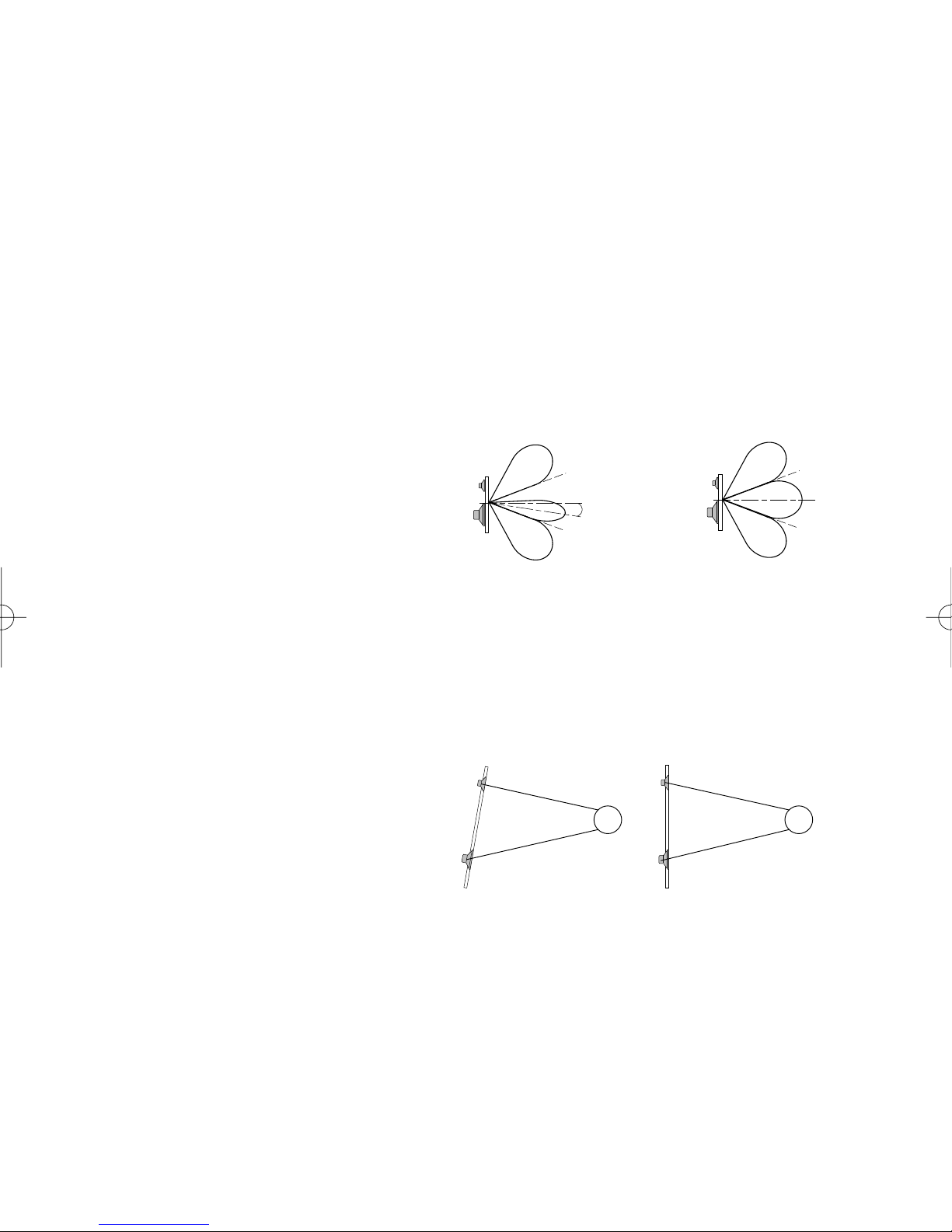
3) el ángulo de radiación de la salida del
altavoz. Varios crossovers dan lugar a
varias salidas con ángulos de radiación
diferentes. A éstos, la salida combinada de más de un altavoz alcanza un máximo. La figura
ilustra el concepto de ángulo de radiación. La variación de los ángulos de radiación se
produce por un desplazamiento de la fase, que es sensible a las frecuencias en el punto de
cruce. El concepto fundamental de elección de curva de un crossover y las características del
corte quedan circunscritos en los puntos siguientes:
a) considerar el sistema de altavoces
b) efecto del desplazamiento de la fase del crossover y colocación de los altavoces respecto a
la respuesta del sistema en frecuencia.
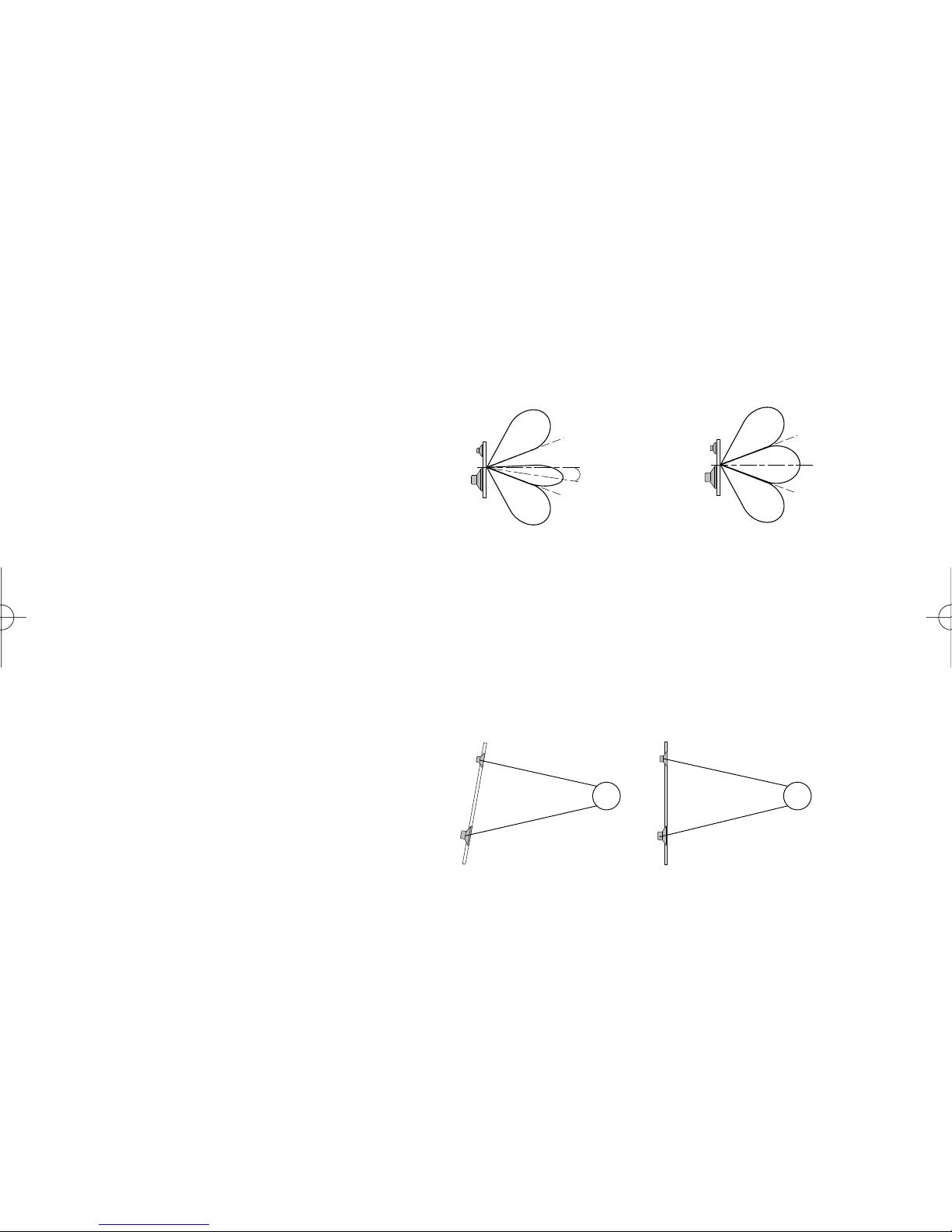
Alineación de fase del crossover y del
altavoz: el modo que hace que un sistema
de altavoces reproduzca minuciosamente
la pulsación de una forma de onda, es el
colocar los altavoces de tal modo que los
frentes de onda lleguen a oidos del
oyente en el mismo momento: el
perfeccionamiento de esta característica se llama alineación de fase, o alineación de tiempo.
La figura debiera ayudar a comprender mejor el concepto. El sonido viaja por el aire a una
velocidad aproximada de 1100 pies/segundo, por lo que una distancia de unas 12 pulgadas
equivale a un retraso de un milisegundo a 1000 Hz: si dos altavoces no están alineados, los
frentes de onda llegan con retraso unos con respecto a otros. Este problema de la alineación
de fase es peor a nivel de frecuencias de corte, porque todos los altavoces están
contribuyendo a la salida acústica total del sistema y, por lo tanto, todo retraso entre fuentes
(woofer, tweeter) crea una respuesta en frecuencia desequilibrada en la región alrededor de la
frecuencia de corte. El modo más sencillo de limitar este problema es ajustar fisicamente la
alineación vertical de los altavoces, hasta que sus centros acústicos queden alineados. Esta
operación hace que la distancia entre altavoz y oyente sea igual para todos los altavoces y
que todos tengan el mismo nivel acústico.
O/M 45.40 (5T) 25/06/02 19:25 Page 5

6
INTRODUCTION
The name of MACROM has always been the synonym of tradition, of a European acoustic and
musical tradition in the pursue of the topmost sound quality and the fact that you chose to buy
this product makes it clear that you due agree with us. With the help of this manual you will be
able to maximise the enjoyment that you will get out of your new 45.40 Mono Amplifier.
This amplifier incorporates many advanced technical features and performances. Therefore, it
is essential that all signals sources, speakers and interconnection devices are of the highest
sonic quality. We strongly recommend the use of MACROM head units, power amplifiers,
speaker systems, high-quality interconnection cables and accessories, because the
integration of all these products is very complex. We therefore advise that you have installed
the 45.40 by your MACROM dealer.
This product has no user-adjustable controls; read this manual carefully in order to become
well acquainted with all the special features and functions of your new MACROM 45.40. Do
not hesitate to contact your MACROM dealer should you have any problem.
PRECAUTIONS
1. The unit may be damaged by wrong lead connection, therefore read carefully the
instructions of this manual for the correct connection of the leads.
2. The last lead to be connected is the one to the positive (+) terminal of the battery; connect
this lead only after having completed and checked all other connections.
3. Be sure to install the crossover in a position with good air circulation and good heat
dissipation.
4. In case of fuse replacement make sure to replace it with a fuse of the same amperage. If
fuses blow more than once, carefully check all electrical connections. Also have your car’s
voltage regulator checked. Do not attempt to repair the unit yourself. If repairs are ever
needed, take the unit to your MACROM dealer or to your nearest MACROM service
station.
5. In order to get the best possible performance from this unit, make sure that the
temperature inside your car is within the range of -10° C and +60° C before you switch the
unit on. Good air circulation is essential to prevent heat build-up inside the unit.
FEATURES
•FIVE-CHANNEL AMPLIFIER, 2CH FRONT, 2CH REAR ALONG WITH MONO SUB
•HIGH-PASS AND LOW-PASS CROSSOVER BY MEANS OF SWITCH
•THREE-POSITION FREQUENCY CUTOFF SELECTOR SWITCH
•CONTINUOUS ADJUSTMENT OF INPUT SENSITIVITY
•CONTINUOUS PHASE ADJUSTMENT OF THE SUB OUTPUT (WAVE ALIGNMENT)
•4CH OR 2CH INPUT SELECTOR
•MOS-FET POWER SUPPLY WITH DUAL DC-DC CONVERTER
•“CHECK CONTROL” STATUS INDICATOR
•THREE PROTECTION DEVICES
•REMOTE ON AND OFF
•GOLD-PLATED RCA INPUT CONNECTIONS
•PROFESSIONAL GOLD-PLATED SCREW-TYPE SUPPLY TERMINALS
O/M 45.40 (5T) 25/06/02 19:25 Page 6

CONTROLS AND INDICATORS
1 • FRONT/SUB INPUT CONNECTORS: Connect the pre-output leads of the head unit to the
input connectors of the amplifier. This input will drive the end section of both the FRONT
section and the SUB one.
2 • REAR INPUT CONNECTORS: Connect the pre-output leads of the head unit to the input
connectors of the amplifier. This input will drive the end section of the REAR section.
3 • 4CH/2CH INPUT MODE SELECTOR:It allows to select the amplifier’s input configuration
as follows:
a) “4ch” - the operation of the five channels depends upon the connection
of the four input channels
b) “2ch” - utilize the FRONT/SUB inputs to drive the five channels by
means of two inputs only.
4 • FRONT CROSSOVER SELECTOR: Il allows to select the FRONT amplifier’s operation
mode:
a) “FLAT”: the FRONT amplifier reproduces the whole audio range on
grounds of the signal present at its input;
b) “63 Hz”: the High-Pass crossover is activated at 63 Hz to determine the
starting value of the high frequencies present at FRONT outputs;
c) “80 Hz”: the High-Pass crossover is activated at 80 Hz to determine
the starting value of the high frequencies present at FRONT outputs.
5 • FRONT INPUT GAIN ADJUSTMENT CONTROL: It allows to adjust input sensitivity to the
FRONT section from 200 mV to 4 V.
6 • REAR CROSSOVER SELECTOR: It allows to select the REAR amplifier’s operation
mode:
a) “FLAT”: the REAR amplifier reproduces the whole audio range on
grounds of the signal present at its input;
b) “63 Hz”: the High-Pass crossover is activated at 63 Hz to determine the
starting value of the high frequencies present at REAR outputs;
c) “80 Hz”: the High-Pass crossover is activated at 80 Hz to determine
the starting value of the high frequencies present at REAR outputs.
7 • REAR INPUT GAIN ADJUSTMENT CONTROL: It allows to adjust input sensitivity to the
REAR section from 200 mV to 4 V.
8 • SUB CROSSOVER SELECTOR: It allows to select the crossover frequency of the SUB
amplifier:
a) “50 Hz”: the Low-Pass crossover is activated at 50 Hz to determine the
end point of the low frequencies present at SUB output;
b) “80 Hz”: the Low-Pass crossover is activated at 80 Hz to determine the
end point of the low frequencies present at SUB output;
c) “120 Hz”: the Low-Pass crossover is activated at 120 Hz to determine
the end point of the low frequencies present at SUB output.
9 • SUB INPUT GAIN ADJUSTMENT CONTROL:
It allows to adjust input sensitivity to the Sub section from 200 mV to 4 V.
7
2 Ch 4Ch
Mode
Flat 63 80Hz
Flat 63 80Hz
50 80 120Hz
O/M 45.40 (5T) 25/06/02 19:25 Page 7

8
CONTROLS AND INDICATORS
10 • SUB OUTPUT PHASE ADJUSTMENT: It allows the continuous phase adjustment in the
region comprised between Min and Max of the SUB output compared to the
FRONT and REAR outputs. The easiest way to determine the “Wave
Alignment” is to use a third-of-octave sound analyzer. Utilize a CD with a
pink noise track and position the microphone exactly at ear level in the
driver’s seat. Adjust the Wave Alignment as follows:
Turn the potentiometer of the “Wave alignment” until the crossover point
between the SUB section and the other sections reaches the maximum
value. The audio analyzer will display the maximum increase.
If the same adjustment is to be made without the relevant instrument, one must rely on his
own ears. Utilize again a CD with a pink noise track or a well known sound track.
Turn the Wave Alignment potentiometer until low frequencies increase.
11 • SPEAKER CONNECTOR: Outputs for speaker connection. The amplifier allows to
connect speakers with minimum 2-ohm impedance per channel.
NOTE: No mono or mixed-mono bridge configuration is possible.
Be sure to keep the right polarity and phase in connecting the speakers.
Avoid any contact between poorly insulated wires and the car’s ground or metal pieces and
between the wires themselves.
12 • BAT + CONNECTOR: to be connected directly to battery + by means of a fuse located
close to the battery itself. Utilize a cable having an adequate section. Do not connect this
cable to the car’s electrical system wiring (eg.: dome-light circuit, car radio etc.)
13 • GND CONNECTOR: connect the ground terminal to a clean base metal part of the
vehicle chassis (if possibile, to an existing screw). Utilize a cable having an adequate section.
14 • REMOTE-ON CONNECTOR: to be connected either to the remote switch-on output lead
or to the output lead of the power antenna coming from the head unit. As a resul, the 45.40
will be switched on and off simultaneously with the head unit.
15 • CHECK CONTROL LED: this led shows the amplifier’s status of operation :
WHITE: the unit is off
GREEN: the unit is working OK
RED: the unit has entered the protection mode
The 45.40 is equipped with three different protection devices:
Overheating: in case of wrong installation the unit enters the protection mode before being
damaged. As soon as the temperature returns to normal values, the unit resumes normal
operation.
Overload: if several speakers are connected to the amplifier and the total impedance
decreases below the allowable threshold (0.5 - 1 ohm), the amplifier enters automatically the
protection mode to avoid any damage. To restore normal operation the head unit has to be
switched off and then on again.
Output short circuit: in case of a short circuit at the speakers outputs, the unit enters the
protection mode to avoid serious damage to the end stage transistors. Normal operation is
restored by eliminating the short circuit and by switching on the head unit again.
Min. Max.
O/M 45.40 (5T) 25/06/02 19:25 Page 8

9
TECHNICAL DATA
RMS Power measured at 12.5 Volts DC:
Total maximum power 450 Watts
Front @ 1 kHz < 0.08 % THD into a 4 ohms load 2 x 45 Watts
Rear @ 1 kHz < 0.08 % THD into a 4 ohms load 2 x 35 Watts
Sub @ 50 Hz < 0.1 % THD into a 4 ohms load 1 x 80 Watts
Dynamic Power measured at 14.4 Volts DC:
Front @ 1 kHz < 0.1 % THD into a 4 ohms load 2 x 65 Watts
Rear @ 1 kHz < 0.1 % THD into a 4 ohms load 2 x 50 Watts
Sub @ 50 Hz < 0.1 % THD into a 4 ohms load 1 x 115 Watts
Front @ 1 kHz into a 2 ohms load 2 x 90 Watts
Rear @ 1 kHz into a 2 ohms load 2 x 70 Watts
Sub @ 50 Hz into a 2 ohms load 1 x 130 Watts
Crossover frequencies
High-Pass, Front/Rear Flat, 63 or 80 Hz
Low-Pass, Sub 50, 80 or 120 Hz
Crossover slope 12 dB/Octave
Frequency response ± 1 dB 10 - 50,000 Hz
Total harmonic distortion 0.08%
Signal-to-noise ratio (IHF A-weighted) > 100 dB
Input sensitivity/Impedance at 12.5Volt DC 200-4000 mV/20 kohms
Speakers’ impedance 2 ohms min
Power supply 14.4 V DC (11-16 V allowed)
Weight 3.5Kg
Size 217(l) x 49(h) x 370(d) mm
Due to continuing improvement, the features and the design are subject to change without
notice.
O/M 45.40 (5T) 25/06/02 19:25 Page 9

10
THEORY OF OPERATION
CONTINUOUS PHASE ADJUSTMENT
The effects of phase shift. The unavoidable consequence of the configuration is the phase
shift, which we will not comment at length as it goes far beyond the boundaries of this
discussion. It is enough to say that any crossover network affecting the signal amplitude also
affects the phase.
What is the phase? The phase is the time reaction between two signals. You probably
encountered this basic problem in connecting two speakers to a stereo system. If the two
speakers are “out of phase”, the bass frequencies are output only partially giving as a result a
“LEAN” sound. On inverting the wires of one speaker the problem can be solved because the
phase of the signal that goes to that speaker is inverted. This is an example for a phase shift
of 180° between two speakers of the same section (low pass); with crossovers it is possible to
have phase shifts also between different sections; they can reach from 0° and change
gradually to 360°.
Phase shift caused by crossover filters affects the following characteristics:
1) the ability of the crossover/speaker
system to reproduce the wave form
2) the flatness of the combined acoustic
output of two or more speakers (low and
high)
3) the radiation angle of the speaker.
Various crossovers produce different
outputs with different radiation angles
where the combined output of several speakers reaches a peak. The figure explains the
concept of radiation. The change of radiation angle is caused by the phase shift that is
sensitive to the frequencies at the crossover point. The fundamental concepts for the choice of
a crossover curve and of the cutoff characteristics are based upon the following:
a) considerations about the speaker system
b) the effect of the phase shift of the crossover and the positioning of the speakers with regard
to the frequency response of the global system.
Phase alignment the crossover and the
speaker: the best way to allow a speaker
system to accurately reproduce the pulses
of a wave pattern is the positioning of the
speakers in such a way that the wave
front coming from different sources
reaches the ears of the listener in exactly
the same time fraction; the improvement
of this characteristic is called phase
alignment or time alignment. This concept is better explained by the figure. Sound travels at a
speed of approx. 1100 ft./sec. through air; therefore, a distance of 12 inches stands for a delay
of one millisecond at 1000 Hz. If two speakers are not well aligned the waves forming the
wave front reach the ear with a delay one with respect to the other. This problem in phase
alignment is particularly acute in the near regions of the cutoff frequencies because all the
speakers contribute to the overall output of the system; any delay between the sound sources
(woofer, tweeter) gives as a result an unbalanced frequency response in the region around the
cutoff frequency. The best way to minimize this problem is to physically correct the vertical
alignment of the different speakers until the perfect alignment of their single acoustic center
points is obtained. Due to this adjustment the distance between the speaker and the listener is
the same for all the speakers within the system thus arranging them on the same acoustic
level.
O/M 45.40 (5T) 25/06/02 19:25 Page 10

11
EINFÜHRUNG
Der Name MACROM ist seit jeher Synonym von Tradition, einer europäischen Tradition von
Sound und Musik, die die beste Tonqualität zum höchsten ZIel gesetzt hat. Die Tatsache, daß
Sie sich für dieses Produkt entschieden haben, beweist, daß auch Sie so denken. Diese
Bedienungsanleitung wird Ihnen dabei helfen, die vielen Eigenschaften dieser neuen Mono
Endstufe 45.40 zu entdecken und vorteilhaft einzusetzen.
Diese Endstufe schließt eine ganze Reihe von besonderen technischen Eigenschaften und
Leistungsmerkmalen ein; aus diesem Grund ist es besonders wichtig, daß alle Signalquellen,
Lautsprecher und Anschlußgeräte von höchster Qualität sind. Wir empfehlen die Verwendung
eines Hauptgeräts, einer Leistungs-Endstufe, von Lautsprechersystemen, Verbindungskabeln
und Zubehör von MACROM, die den höchsten Qualitätsanforderungen entsprechen, denn die
Verbindung dieser Geräte ist äußerst komplex. Aus diesem Grund raten wir, die Endstufe
45.40 von Ihrem MACROM-Vertragshändler installieren zu lassen.
Diese Endstufe von MACROM hat keine Einstellungen und Regelungen, die vom Anwender
benutzt werden können. Lesen Sie diese Bedienungsanleitung sehr sorgfältig, um sich mit den
besonderen Eigenschaften und Funktionen Ihrer neuen Endstufe 45.40 von MACROM
vertraut zu machen. Wenden Sie sich im Zweifelsfalle vertrauensvoll an Ihren MACROM-
Vertragshändler.
VORSICHTSMAßNAHMEN
1. Jegliche falsche Verbindung könnte das Gerät beschädigen. Lesen Sie aufmerksam die
Anleitungen für den Kabelanschluß durch.
2. Das Batteriekabel zuletzt an den Pluspol (+) der Batterie anschließen und nur, nachdem
alle anderen Anschlüsse ausgeführt worden sind.
3. Man vergewissere sich, daß die elektronische Frequenzweiche an einer Stelle installiert
wird, wo gute Luftzirkulation und eine gute Wärmeabgabe gewährleistet sind.
4. Die Sicherungen müssen immer durch Sicherungen mit der gleichen Amperezahl ersetzt
werden, um schwere Beschädigungen der Gerätekomponenten zu vermeiden. Man lasse
bei mehrmaligem Durchbrennen der Sicherungen die Lichtmaschine des Wagens
überprüfen. Das Gerät niemals selber reparieren, sondern jegliche Reparatur Ihrem
MACROM-Vertragshändler oder der nächsten MACROM-Dienststelle übergeben.
5. Um die besten Leistungen zu erzielen sollte die Temperatur im Wageninnenraum zwischen
-10° C und +60° C liegen, bevor man das Gerät einschaltet.
EIne gute Lüftung des Wageninnenraums ist erforderlich, um die Überhitzung der inneren
Stromkreise des Gerätes zu vermeiden.
EIGENSCHAFTEN
•5-KANAL-VERSTÄRKER, 2 FRONT-KANÄLE, 2 REAR-KANÄLE PLUS MONO-SUB-KANAL
•HIGH-PASS- UND LOW-PASS-CROSSOVER ÜBER SWITCH
•TRENNFREQUENZ-WAHLSCHALTER MIT 3 POSITIONEN
•STUFENLOSE EINGANGS-EMPFINDLICHKEITSREGELUNG
•STUFENLOSE SUB-AUSGANGSPHASENREGELUNG (WAVE ALIGNMENT)
•4-KANAL- ODER 2-KANAL-EINGANGSWAHLSCHALTER
•MOS-FET-SPEISUNG MIT DOPPELTEM DC-DC-UMFORMER
•“CHECK CONTROL”-STATUSANZEIGE
•DREIFACH-SCHUTZ
•REMOTE-EIN- UND -AUSSCHALTUNG
•VERGOLDETE RCA-EINGANGSANSCHLÜSSE
•VERGOLDETE, PROFESSIONELLE SCHRAUBANSCHLÜSSE
O/M 45.40 (5T) 25/06/02 19:25 Page 11

12
EINSTELLUNGEN UND ANZEIGEN
1 • FRONT/SUB-EINGANGSVERBINDER: Die Ausgangskabel ´Pre´ Ihres Hauptgerätes an
die Eingangsverbinder des Verstärkers anschließen. Dieser Eingang steuert die Endstufe des
FRONT- und des SUB-Bereiches.
2 • REAR-EINGANGSVERBINDER: Die Ausgangskabel ´Pre´ Ihres Hauptgerätes an die
Eingangsverbinder des Verstärkers anschließen. Dieser Eingang steuert die Endstufe des
REAR-Bereiches.
3 • WAHLSCHALTER FÜR DEN 2-KANAL/4-KANAL-EINGANGSMODUS (2ch/4ch):
Dient zur Einstellung der Verstärkerkonfiguration wie folgt:
a) “4ch”: Es müssen die vier Kanäle angeschlossen werden, um die
Funktionstüchtigkeit der 5 Kanäle zu gewährleisten
b) “2ch”: Die Front-/Sub-Eingänge zur Steuerung der 5 Kanäle mit nur zwei
Eingängen benutzen
4 • WAHLSCHALTER FÜR FRONT-CROSSOVER: Dient zur Einstellung des FRONT-
Verstärkerbetriebsmodus.
a)”FLAT”: Der FRONT-Verstärker gibt den gesamten Tonbereich des an
seinem Eingang anliegenden Tonsignals wieder.
b) “63 Hz”: Der 63Hz-Crossover-High-Pass-Filter wird eingeschalten, d.h.
es wird der Beginn der an den FRONT-Ausgängen anliegenden hohen
Frequenzen bestimmt.
b)”80Hz”: Der 80Hz-Crossover-High-Pass-Filter wird eingeschalten, d.h. es
wird der Beginn der an den FRONT-Ausgängen anliegenden hohen
Frequenzen bestimmt.
5 • EINSTELLUNG DES FRONT-EINGANGSGEWINNS:
Dient zur Einstellung der Eingangsempfindlichkeit zwischen 200mV und 4 V im Front-Bereich.
6 • WAHLSCHALTER FÜR REAR-CROSSOVER: Dient zur Einstellung des REAR-
Verstärkerbetriebsmodus
a)”FLAT”: Der REAR-Verstärker gibt den gesamten Tonbereich des an
seinem Eingang anliegenden Tonsignals wieder.
b) “63 Hz”: Der 63Hz-Crossover-High-Pass-Filter wird eingeschalten, d.h.
es wird der Beginn der an den REAR-Ausgängen anliegenden hohen
Frequenzen bestimmt.
b)”80Hz”: Der 80Hz-Crossover-High-Pass-Filter wird eingeschalten, d.h. es
wird der Beginn der an den REAR-Ausgängen anliegenden hohen
Frequenzen bestimmt.
7 • EINSTELLUNG DES REAR-EINGANGSGEWINNS: Dient zur Einstellung der
Eingangsempfindlichkeit zwischen 200mV und 4 V im Rear-Bereich.
8 • WAHLSCHALTER FÜR SUB-CROSSOVER:
Dient zur Einstellung der Frequenz des SUB-Verstärker-Crossovers
a) “50 Hz”: Der 50Hz-Crossover-Low-Pass-Filter wird eingeschalten, d.h.
es wird das Ende der am SUB-Ausgang anliegenden
niedrigen.Frequenzen bestimmt
b) “80 Hz”: Der 80Hz-Crossover-Low-Pass-Filter wird eingeschalten, d.h.
es wird das Ende der am SUB-Ausgang anliegenden
niedrigen.Frequenzen bestimmt.
b) “120 Hz”: Der 120Hz-Crossover-Low-Pass-Filter wird eingeschalten,
d.h. es wird das Ende der am SUB-Ausgang anliegenden niedrigen.Frequenzen bestimmt.
9 • EINSTELLUNG DES SUB-EINGANGSGEWINNS:
Dient zur Einstellung der Eingangsempfindlichkeit zwischen 200mV und 4 V im SUB-Bereich.
2 Ch 4Ch
Mode
Flat 63 80Hz
Flat 63 80Hz
50 80 120Hz
O/M 45.40 (5T) 25/06/02 19:25 Page 12

13
EINSTELLUNGEN UND ANZEIGEN
10 • SUB-AUSGANGSPHASENEINSTELUNG: Dient zur stufenlosen SUB-
Ausgangsphasenregelung im Bereich zwischen Min und Max im Verhältnis zu den Front- und
Rear-Ausgängen.
Man regelt das “Wave Alignment” am besten mit einem Terzband-
Klanganalysator. . Mittels eines CD mit einer Spur für die Wiedergabe des
Rosa-Rauschsignals sowie bei präziser Positionierung des Mikrofons auf
Ohrhöhe am Fahrersitz kann das Wave Alignment wie folgt eingestellt
werden:
Den Wave-Alignment-Knopf soweit drehen, daß der Kreuzpunkt zwischen
Sub und den anderen Bereichen auf den Höchstwert ansteigt. Die Höchstzunahme wird am
Klanganalysator angezeigt.
Soll dieselbe Einstellung hingegen ohne die Benutzung von Geräten erfolgen, muß auf das
Gehör zurückgegriffen werden. Dazu muß ebenfalls ein CD mit einer Rosa-Rauschsignal-
Wiedergabespur benutzt werden, auf dem ein Ihnen bekanntes Musikstück aufgezeichnet ist.
Den Wave-Alignment-Knopf drehen, bis die Zunahme der niedrigen Frequenzen zu hören ist.
11 • LAUTSPRECHERVERBINDER:Ausgangsverbinder für den Anschluß der Lautsprecher.
An den Verstärker können Lautsprecher mit einer Mindestimpedanz von 2 Ohm pro Kanal
angeschlossen werden.
ANMERKUNG:
Es können keine Brückenanschlüsse für Mono- oder gemischten Mono-Betrieb ausgeführt
werden.
Beim Anschluß der Lautsprecher ist auf die korrekte Polschaltung und Phase zu achten.
Massekontakte bzw. Kontakte mit Metallteilen des Autos von nicht entsprechend isolierten
Kabeln bzw. Kontakte zwischen diesen Kabeln sind zu vermeiden.
12 • BATT-Anschluß:Den Anschluß mit einem entsprechend dicken Kabel über eine nahe an
der Batterie befindliche Sicherung direkt am +Pol der Batterie ausführen. Dieses Kabel darf
nicht an einen Stromkreis des Autos angeschlossen werden (z.B. an den Stromkreis der
Deckenlampen oder des Autoradios usw.).
13 • GND-ANSCHLUSS: Die Masseklemme mit einem entsprechend dicken Kabel an einer
sauberen Stelle des Chassis-Metallteils des Autos (wenn möglich an einer bereits
vorhandenen Schraube) anschließen.
14 • REMOTE-ON-ANSCHLUSS: Er muß an das Remote-on-Ausgangskabel
(Ferneinschaltung) oder an die automatische Antenne des Hauptgerätes angeschlossen
werden. Damit kann das Gerät 45.40 über das Hauptgerät ein- und ausgeschalten werden.
15 • CHECK CONTROL ANZEIGE:Dieses LED zeit den Betriebsstatus des Verstärkers an.
WEISS: Das Gerät ist ausgeschalten.
GRÜN: Das Gerät funktioniert einwandfrei
ROT: Das Gerät steht unter Schutz. Das Gerät 45.40 verfügt über drei Schutzvorrichtungen:
Überhitzungsschutz: Bei Installationsfehlern wirkt der Schutz vor Beschädigung des Gerätes
ein. Sobald die Temperatur wieder auf normale Werte absinkt, wird das Gerät wieder
eingeschalten. Überlastungsschutz: Falls mehrere Lautsprecher an den Verstärker
angeschlossen werden und die Gesamtimpedanz unter die zulässigen Grenzwerte 0,5-1 Ohm
sinkt, wird der Verstärker durch Selbstschutz außer Betrieb gesetzt. Zum Wiedereinschalten
muß das Hauptgerät aus- und wieder eingeschalten werden.
Kurzschluß am Ausgang: Bei Kurzschluß an den Lautsprecherausgängen wird die
Schutzfunktion zwecks Vermeidung hoher Endtransistorschäden ausgelöst. Durch
Beseitigung des Kurzschlusses und Wiedereinschalten des Hauptgeräts wird der
Normalbetrieb wieder hergestellt.
Min. Max.
O/M 45.40 (5T) 25/06/02 19:25 Page 13

14
TECHNISCHE DATEN
RMS Leistung gemessen an 12,5 Volt DC:
Höchstleistung max. 450 Watt
Ausgang / Front 1 kHz < 0,08 % THD an 4 Ohm 2 x 45 Watt
Ausgang / Heck 1 kHz < 0,08 % THD an 4 Ohm 2 x 35 Watt
Ausgang / Subwoofer 50 Hz < 0,1 % THD an 4 Ohm 1 x 80 Watt
Dynamische Spitzenleistung gemessen an 14,4 Volts DC:
Ausgang / Front 1 kHz < 0,1 % THD an 4 Ohm 2 x 65 Watt
Ausgang / Heck 1 kHz < 0,1 % THD an 4 Ohm 2 x 50 Watt
Ausgang / Subwoofer 50 Hz < 0,1 % THD an 4 Ohm 1 x 115 Watt
Ausgang / Front 1 kHz an 2 Ohm 2 x 90 Watt
Ausgang / Heck 1 kHz an 2 Ohm 2 x 70 Watt
Ausgang / Subwoofer 50 Hz an 2 Ohm 1 x 130 Watt
Frequenzregelung:
High-Pass, Front / Heck 0-, 63-, 80 Hz
Low-Pass, Subwoofer 50-, 80-, 120 Hz
Flankensteilheit 12 dB/Octave
Frequenzbereich ± 1 dB 10 - 50.000 Hz
Klirrfaktor 0,08%
Rauschspannungsabstand >100 dB
Eingangsempfindlichkeit / Impedanz 200-4000 mV/20 kOhm
Lautsprecherimpedanz 2 Ohm min.
Stromversorgung 14,4 V DC (11-16 V möglich)
Gewicht 3.5 Kg
Maße 217(l) x 49(h) x 370(d) mm
Änderungen der technischen Daten und Designs zwecks Verbesserung vorbehalten.
O/M 45.40 (5T) 25/06/02 19:25 Page 14

FUNKTIONSPRINZIP
STUFENLOSE PHASENVERSTELLUNG.
Die Auswirkungen der Phasenverstellung. Ein unvermeidlicher Nachteil der High-Pass, Low-
Pass und Band-Pass-Konfiguration ist die Phasenverschiebung, aber darüber werden wir uns
nicht länger auslassen, denn dieses Thema würde den Rahmen dieser Diskussion sprengen.
Es genügt zu wissen, daß ein Netz von Frequenzweichen, das die Amplitüde des Signals
beeinflußt, ebenfalls die Phase beeinflußt.
Was ist die Phase? Die Phase ist die Zeitreaktion zwischen zwei Signalen. Dieses Problem
hat sich Ihnen wahrscheinlich auch schon bei dem Anschluß von zwei Lautsprechern
innnerhalb einer Stereoanlage gestellt. Wenn die beiden Lautsprecher nicht “IN PHASE” sind,
werden die niedrigen Ausgangsfrequenzen nur teilweise wiedergegeben, was zu einem
System mit einem “LEEREN” Sound führt. Invertiert man die Drähte eines der Lautsprecher,
so kann man Abhilfe schaffen, denn man invertiert die Phase des Signals jenes
Lautsprechers. Dieses ist ein Beispiel für eine Phasenverschiebung von 180° zwischen zwei
Lautsprechern desselben Frequenzbereiches (low pass); mit den Frequenzweichen können
Phasenverschiebungen aber auch zwischen Lautsprechern verschiedener Frequenzbereiche
auftreten; sie beginnen bei 0° und verändern sich allmählich bis 360°.
Die von Frequenzweichen verursachten Phasenverschiebungen wirken sich auf folgende
Faktoren aus:
1) die Fähigkeit des von der
Frequenzweiche und dem Lautsprecher
gebildeten Systems, die Wellenform
wiederzugeben
2) die Flachheit der kombinierten
akustischen Wiedergabe zweier oder
mehrerer Lautsprecher (low und high)
3) den Streuwinkel des Lautsprechers.
Verschiedene Frequenzweichen führen zu unterschiedlichen Wiedergaben mit verschiedenen
Streuwinkeln, bei denen die kombinierte Wiedergabe mehrerer Lautsprecher einen Höhepunkt
erreicht. Die Abbildung erläutert das Konzept von Streuwinkel. Die Änderung des Streuwinkels
erfolgt aufgrund der Phasenverschiebung, die von der Frequenz an der Übergangsstelle
abhängt. Das grundlegende Konzept für die Auswahl der Kennlinie einer Frequenzweiche und
der Übergangseigenschaften beruht auf folgenden Faktoren:
a) Betrachtungen über das Lautsprechersystem
b) Auswirkung der Phasenverschiebung der Frequenzweiche und Anordnung der
Lautsprecher in Abhängigkeit vom Frequenzgang des Systems.
Ausrichtung der Phase der
Frequenzweiche und des Lautsprechers:
Die Methode, die es einem
Lautsprechersystem ermöglicht, eine
Wellenform getreu wiederzugeben,
besteht in der korrekten Anordnung der
Lautsprecher; sie müssen so ausgerichtet
werden, daß die Wellenfront exakt im
selben Augenblick die Ohren des Hörers erreicht; die Perfektionierung dieser Eigenschaft wird
Phasenabgleich oder Zeitabgleich genannt. Dieses Konzept ist in der Abbildung erläutert. Der
Schall breitet sich in der Luft mit einer Geschwindigkeit von etwa 1100 Fuß pro Sekunde aus
und eine Distanz von 12 Zoll bedeutet eine Verzögerung von einer Millisekunde bei 1000 Hz;
bei zwei nicht abgeglichenen Lautsprechern breiten sich die Wellenfronten mit einer
Verzögerung zueinander aus. Dieses Problem des Phasenabgleichs ist besonders in der
Nähe der Übergangsfrequenz besonders auffällig, denn alle Lautsprecher tragen zu der
Wiedergabe des gesamten Tonspektrums bei und jegliche Verzögerung zwischen den
verschiedenen Tonquellen (Tiefbaßtöner, Hochtöner) führt zu einem unausgeglichenen
Frequenzgang im Bereich der Übergangsfrequenz. Die einfachste Weise, um dieses Problem
so niedrig wie möglich zu halten, besteht darin, die Lautsprecher so anzuordnen, daß die
akustischen Mittelpunkte alle auf einer Linie liegen. Dadurch ist die Distanz zwischen allen
Lautsprechern und dem Hörer gleich und sie befinden sich auf derselben akustischen Ebene.
15
O/M 45.40 (5T) 25/06/02 19:25 Page 15

INTRODUCTION
Depuis toujours, le nom de MACROM est synonyme de tradition, d’une tradition acoustique et
musicale européenne projeté vers la conquête de la meilleure qualité sonore. Le fait que vous
ayez choisi ce produit signifie que vous êtes d’accord avec nous. Grâce à ce manuel vous
pourrez apprécier toutes le caractéristiq ues avancées de ce nouveau Mono Amplificateur
45.40.
Ce séparateur à 2 voies renferme toute une série de caractéristiques techniques et des
performances remarquables et il est donc très important que toutes les sources de signal, les
haut-parleurs et les appareils d’interconnexion soient d’une qualité excellente: Nous
recommendons l’utilisation d’unités principales, d’amplificateur de puissance, de systèmes de
haut-parleurs, de câbles de connexion et d’accessoires de haute qualité de MACROM,
puisque l’intégration de ces produits est de nature assez complexe, et nous vous conseillons
de faire installer ce 45.40 par votre revendeur MACROM autorisé.
Ce amplificateur n’a pas de commandes ou de contrôles réglables par l’utilisateur; lisez
attentivement ce manuel pour vous familiariser avec les caractéristiques spéciales et les
fonctions de votre nouveau 45.40 de MACROM. En cas de doute adressez-vous à votre
revendeur MACROM autorisé.
PRECAUTIONS
1. Toute mauvaise connexion pourrait endommager l’unité. Lire attentivement les instructions
pour la connexion des fils données dans ce manuel.
2. Il faut connecter le fil de la batterie au terminal (+) de la batterie même en dernier et
seulement après avoir effectué et contrôlé toutes les autres connexions.
3. Il faut s’assurer que le séparateur soit installé dans une position avec une bonne circulation
d’air et une bonne dissipation de la chaleur.
4. Les fusibles doivent toujours être remplacé avec des fusibles du même ampérage pour
éviter de graves dommages aux composants de l’appareil. Si les fusibles devaient sauter
plusieurs fois de suite, faire contrôler le régulateur de voltage de votre voiture. N’essayez
jamais de réparer l’appareil vous-même, mais confiez-la au distributeur MACROM ou au
centre d’assistance MACROM de votre zone.
5. Pour obtenir les meilleures performances de votre appareil faites en sorte que la
température à l’intérieur de la voiture soit comprise entre -10° C et +60° C avant d’allumer
l’appareil. Une bonne ventilation est indispensable pour éviter la surchauffe des circuits
internes.
CARACTERISTIQUES
•AMPLIFICATEUR À CINQ CANAUX, 2CH FRONT, 2CH REAR PLUS SUB EN MONO
•SÉPARATEUR LOW-PASS ET HIGH-PASS PAR MOYEN DE L’INTERRUPTEUR
•SÉLECTEUR DES FRÉQUENCES DE COUPE À TROIS POSITIONS
•RÉGLAGE CONTINU DE LA SENSIBILITÉ D’ENTRÉE
•RÉGLAGE CONTINU DE LA PHASE DE LA SORTIE SUB (WAVE ALIGNMENT)
•SÉLECTEUR D’ENTRÉE 4CH OU 2CH
•ALIMENTATEUR MOS-FET AVEC CONVERTISSEUR DUEL DC-DC
•INDICATEUR D’ÉTAT “CHECK CONTROL”
•TROIS PROTECTIONS DIFFÉRENTES
•ALLUMAGE ET EXTINCTION À DISTANCE
•TERMINAUX D’ENTRÉE RCA DORÉS
•TERMINAUX D’ALIMENTATION PROFESSIONELS À VIS, DORÉS
16
O/M 45.40 (5T) 25/06/02 19:25 Page 16

17
CONTROLES ET INDICATEURS
1 • CONNECTEURS D’ENTREE FRONT/SUB: Il faut relier les fils de sortie Pre de l’unité
principale aux connecteurs d’entrée. Cette entrée va piloter l’étage final de la section FRONT
ainsi que celui de la section SUB.
2 • CONNECTEURS D’ENTREE REAR: Il faut relier les fils de sortie Pre de l’unité principale
aux connecteurs d’entrée. Cette entrée va piloter l’étage final de la section REAR
3 • SELECTEUR DU MODE D’ENTREE 4CH/2CH: Il permet de sélectionner la configuration
d’entrée de l’amplificateur, comme suit:
a) “4ch” - il faut relier les quatre canaux d’entrée pour que les cinq canaux
fonctionnent;
b) “2ch” - il faut utiliser les entrées FRONT/SUB afin de piloter les cinq
canaux uniquement avec deux entrées.
4 • SELECTEUR DU CROSSOVER FRONT:
Il permet de sélectionner le mode de fonctionnement de l’amplificateur FRONT:
a) “FLAT”: L’amplificateur FRONT reproduit toute la gamme audio par
rapport au signal audio présent à son entrée;
b) “63 Hz”: Le séparateur High-Pass est activé à 63 Hz afin de determiner
le départ des hautes fréquences présentes aux sorties FRONT;
c) “80 Hz”: Le séparateur High-Pass est activé à 80 Hz afin de determiner
le départ des hautes fréquences présentes aux sorties FRONT.
5 • REGLAGE DU GAIN A L’ENTREE FRONT:
Il permet le réglage de la sensibilité d’entrée à la section FRONT de 200 mV à 4V.
6 • SELECTEUR DU CROSSOVER REAR: Il permet de sélectionner le mode de
fonctionnement de l’amplificateur REAR:
a) “FLAT”: L’amplificateur REAR reproduit toute la gamme audio par
rapport au signal audio présent à son entrée;
b) “63 Hz”: Le séparateur High-Pass est activé à 63 Hz afin de determiner
le départ des hautes fréquences présentes aux sorties REAR;
c) “80 Hz”: Le séparateur High-Pass est activé à 80 Hz afin de determiner
le départ des hautes fréquences présentes aux sorties REAR.
7 • REGLAGE DU GAIN A L’ENTREE REAR: Il permet le réglage de la sensibilité d’entrée à
la section REAR de 200 mV à 4V.
8 • SELECTEUR DU CROSSOVER SUB: Il permet de sélectionner la fréquence du crossover
de l’amplificateur SUB:
a) “50 Hz”: Le séparateur Low-Pass est activé à 50 Hz afin de déterminer
la fin des basses fréquences présentes à la sortie SUB.
b) “80 Hz”: Le séparateur Low-Pass est activé à 80 Hz afin de déterminer
la fin des basses fréquences présentes à la sortie SUB;
c) “120 Hz”: Le séparateur Low-Pass est activé à 120 Hz afin de
determiner la fin des basses fréquences présentes à la sortie SUB.
9 • REGLAGE DU GAIN A L’ENTREE SUB: Il permet le réglage de la sensibilité d’entrée à la
section SUB de 200 mV à 4V.
2 Ch 4Ch
Mode
Flat 63 80Hz
Flat 63 80Hz
50 80 120Hz
O/M 45.40 (5T) 25/06/02 19:25 Page 17

18
CONTROLES ET INDICATEURS
10 • REGLAGE DE LA PHASE DE LA SORTIE SUB: Réglage continu dans les zones entre
Min et Max de la phase de la sortie SUB par rapport aux sorties FRONT et REAR.
La façon la plus simple de fixer le “Wave Alignment” est celle d’utiliser un
analyseur audio de tiers d’octave. En utilisant un CD ayant une piste avec
du bruit rose et en positionnat le microphone à la hauteur de l’oreille à la
place du conducteur, réglez le “Wave Alignment” comme suit:
Tournez le “Wave Alignment” jusqu’à atteindre la valeue maximun du point
de croisement entre la section SUB et les autres sections. L’analyseur audio
va afficher l’augmentation maximale.
Si l’on veut effectuer le m^eme réglage sans l’aide d’instruments, il faut se fier à ses propres
oreilles. Il faut utiliser de nouveau un CD ayant une piste avec du bruit rose ou bien une plage
musicale bien connue. Tournez le Wave Alignment jusqu’à augmenter les basses fréquences.
11 • CONNECTEUR SPEAKER: Sorties pour la connexion des haut-parleurs.
L’amplificateur permet la connexion de haut-parleurs ayant une impédance de 2 Ohm
minimum par canal.
NOTE: Il ne faut faire aucune connexion pontée pour le fonctionnement mono ou “mixed
mono”.
Assurez-vous d’observer la bonne polarité et la phase pendant la connexion des haut-
parleurs. Evitez que les fils non isolés puissent enter en contact avec la masse, avec les
parties métalliques de la voiture ou ne fassent contact entre eux.
12 • CONNECTEUR + BAT: il doit être relié directement au pôle positif (+) de la batterie en
interposant un fusible près de celle-ci. Il faut utiliser un fil ayant une section adéquate. Ne
reliez pas ce connecteur au circuit électrique de la voiture (par exemple, lumières internes,
autoradio etc.).
13 • CONNECTEUR GND (Masse): il doit être relié, en utilisant un fil ayant une section
adéquante, à un point métallique proprie du châssis de la voiture (si possible à une vis déjà
installée).
14 • CONNECTEUR REMOTE-ON: il doit être relié au fil de sortie de l’allumage remote-on
(allumage à distance) ou de l’antenne automatique qui sort de l’unité principale. Ceci permet
d’allumer et d’éteindre le 45.40 en allumant et éteignant l’unité principale.
15 • LED CHECK CONTROL: cette LED indique l’état de fonctionnement de l’amplificateur.
BLANC: l’unité est éteinte
VERT: l’unité fonctionne très bien.
ROUGE: l’unité est entrée en état de protection.
Le 45.40 est èquipé de trois pretections différentes:
- surchauffe: en cas d’erreurs d’installation, l’unité entre en état de protection avant de subir
des dommages. Dès que la température retourne à des valeurs normales, l’unité reprend son
fonctionnemen normal;
- surcharge: si plusieurs haut-parleurs sont connectés à l’amplificateur et l’impédance totale
est inférieure au seuil permis (0,5-1 ohm) l’amplificateur entre automatiquement en état de
protection. Pour que l’unité reprenne son fonctionnement normal, il faut éteindre et allumer de
nouveau l’unité principale;
- court circuit à la sortie: en cas de court circuit à la sortie des haut-parleurs, l’unité entre en
état de protection pour prévenir de sérieux dommages aux transistors finaux. Pour qu’elle
revienne à l’état de fonctionnement normal, il faut éliminer le court circuit et allumer de
nouveau l’unité principale.
Min. Max.
O/M 45.40 (5T) 25/06/02 19:25 Page 18

19
CARACTERISTIQUES TECHNIQUES
Puissance RMS sous 12,5 Volts DC:
Puissance totale maximum 450 Watts
Avant @ 1 kHz < 0,08 % THD sous 4Ω 2 x 45 Watts
Arrière @ 1 kHz < 0,08 % THD sous 4Ω 2 x 35 Watts
Sub @ 50 Hz < 0,1 % THD sous 4Ω 1 x 80 Watts
Puissance dynamique sous 14,4 Volts DC:
Avant @ 1 kHz < 0,1 % THD sous 4Ω 2 x 65 Watts
Arrière @ 1 kHz < 0,1 % THD sous 4Ω 2 x 50 Watts
Sub @ 50 Hz < 0,1 % THD sous 4Ω 1 x 115 Watts
Avant @ 1 kHz sous 2Ω 2 x 90 Watts
Arrière @ 1 kHz sous 2Ω 2 x 70 Watts
Sub @ 50 Hz sous 2Ω 1 x 130 Watts
Filtrage actif
Passe haut sur avant et arrière Flat, 63 ou 80 Hz
Passe bas sur Sub 50, 80 ou 120 Hz
Pente de filtrage 12 dB/Octave
Réponse en fréquence ± 1 dB 10 - 50.000 Hz
Taux de distorsion total 0.08%
Rapport signal sur bruit > 100 dB
Sensibilité d’entrée sous 12.5Volt DC 200-4000 mV/20 kΩ
Impédance minimum 2Ω
Alimentation 14,4 V DC (11 à 16 V possible)
Poids 3.5 Kg
Taille 217(l) x 49(h) x 370(d) mm
En raison des améliorations constantes apportées aux produits, les caractéristiques sont
susceptibles de changer sans préavis.
O/M 45.40 (5T) 25/06/02 19:25 Page 19

PRINCIPE DE FONCTIONNEMENT
REGLAGE DE LA PHASE EN CONTINU.
Les effets du déplacement de phase. Une conséquence inévitable de la configuration des
filtres hipass, lowpass et bandpass est le déplacement de la phase, mais nous n’allons pas
approfondir ce thème puisqu’il va au delà des limites de cette discussion. Il suffit de savoir que
tout réseau de séparateur qui a des effets sur l’amplitude du signal aura aussi des effets sur la
phase.
Qu’estce qu’est la phase? C’est la réaction de temps entre deux signaux. Vous avez
probablement déjà connu ce problème de base pendant la connexion de deux hautparleurs
dans une chaîne HIFI. Si les deux hautparleurs ne sont pas en “PHASE”, les fréquences
graves ne sont reproduites que partiellement et le résultat est une chaîne avec une sonorité
“PAUVRE”. En intervertissant les fils d’un des hautparleurs on corrige le problème, parce
qu’on intervertit la phase du signal allant à ce hautparleur. Ceci est un exemple de
déplacement de phase de 180° entre deux hautparleurs de la même section (low pass); avec
les séparateurs on peut avoir aussi des déplacements de phase entre les différentes sections
et qui partent de 0° et changent graduellement jusqu’à 360°.
Le déplacement de phase, causé par les filtres séparateurs, a des effets sur les éléments
suivants:
1) l’habileté du système
séparateur/hautparleurs de reproduire les
formes d’onde
2) l’aplatissement de la sortie acoustique
combinée de deux ou plusieurs
hautparleurs (Low et High)
3) l’angle de radiation de la sortie du
hautparleur. Plusieurs séparateurs
donnent lieu à des sorties différentes avec des angles de radiation différents avec lesquels la
sortie combinée de plusieurs hautparleurs atteint le maximum. La figure illustre le concept
d’angle de radiation. Le changement de l’angle de radiation se produit à cause du
déplacement de phase qui est sensible aux fréquences au point de croisement. Le concept
fondamental pour le choix de la courbe d’un séparateur et des caractéristiques de coupe se
fonde sur les points suivants:
a) considérations sur le système de hautparleurs,
b) effet du déplacement de la phase du séparateur et positionnement des hautparleurs par
rapport à la réponse en fréquence du système.
Alignement de la phase du séparateur et
du hautparleur: pour faire en sorte qu’un
système de haut-parleurs puisse
reproduire de façon précise la pulsation
d’une forme d’onde, il faut positionner les
hautparleurs de façon telle que les ondes
formant un front acoustique arrivent aux
oreilles de l’écouteur exactement en
même temps; le perfectionnement de
cette caractéristique est appelé alignement de phase ou alignement de temps. La figure ici à
côté devrait illustrer mieux le concept. Le son se propage à une vitesse approximative de
1000 pieds/seconde dans l’air; une distance d’environ 12 pouces représente donc un retard
d’une milliseconde à 1000 Hz; si deux hautparleurs ne sont pas alignés, les ondes qui forment
le front des ondes arrivent en retard les unes par rapport aux autres. Ce problème
d’alignement de phase est particulièrement mauvais en correspondance des fréquences de
coupe, parce que tous les hautparleurs contribuent à la sortie acoustique totale du système;
tout retard entre les sources sonores (woofer, tweeter) résultera donc en une réponse en
fréquence déséquilibrée dans la région autour de la fréquence de coupe. La manière la plus
simple pour minimiser ce problème est d’ajuster physiquement l’alignement vertical des
différents hautparleurs jusqu’à ce que leurs centres acoustiques soient alignés. Cette
opération rend égale la distance entre le hautparleur et l’écouteur les plaçant sur le même
niveau acoustique.
20
O/M 45.40 (5T) 25/06/02 19:25 Page 20
Table of contents
Languages:
Other Macrom Car Amplifier manuals