Magnum Industrial MI-76390 User manual

MODEL NO.: MI-76390
PARTS BREAKDOWN

ASSEMBLY INSTRUCTIONS for Magnum Industrial Drill Press
MODEL: MI-76390
Before you assemble your drill press, review the parts breakdown and keep it ready for
reference.
● Start by removing the parts from the packaging.
● Carefully check the packaging for small pieces before you continue.
● Lay out the parts on a large, clear and unobstructed area and ensure that all parts are
accounted for.
ASSEMBLING THE DRILL PRESS
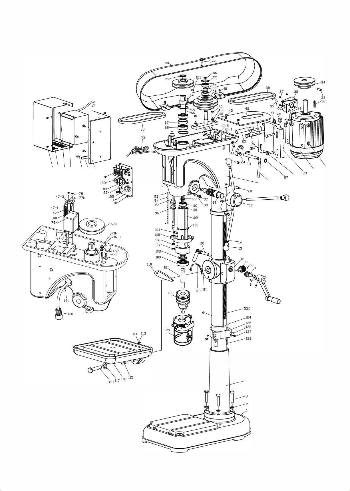
1. Fasten the column (4) to the base (1) with the four bolts (3)
2. Remove the rack collar (16) from the column (6) by tapping and rotating it slowly
upwards.
3. Make sure the raising gears (10) (9) are in place. Insert the rack (5N) into the table
bracket (12) and lower these two pieces onto the column at the same time. This may
require two people or a forklift. The bottom of the rack (5N) slips into the slot provided on
the lower collar (124). The top of the rack (5N) is held in place by the rack collar (16).
Place the collar on the column and tighten the set screw (15).
4. Place the handle (7) on the worm gear shaft (9) and secure it with the hex head bolt (8)
5. Lower the main head onto the column and secure it with the set screws (20). This
requires at least two people.
6. Attach the three feed handles (14) and knobs (13).
Once assembled, clean the protective coating from all surfaces (where applicable) using a rag
dipped in kerosene, mineral spirits or paint thinner. (Dispose of potentially flammable
solvent-soaked rags according to manufacturer’s safety recommendations.)
A putty knife, held flat to avoid scratching the surface, may also be used to scrape off the
coating followed by clean-up with solvent.
Avoid rubbing painted surfaces, as many solvent-based products will remove paint.
INSTALLING THE CHUCK
1. Degrease all pieces.
2. Slide the arbor (121) into the spindle (102) flat end up.
3. Slide the chuck (120) over the tapered end of the arbor and, using a wooden mallet, give
the chuck a good tap. The taper is designed to hold the chuck securely in place.
If you have any questions or require further information, please contact KMS Tools Service
Department at 604.395.4134 or email [email protected]

CONTROLLING SPINDLE SPEED
The MI-76390 has two speed variable
speed ranges: 280 to 1,140 rpm and
800 to 3,200 rpm. You can select the
setting by repositioning the drive belt
on the pulleys. See the next page for
instructions on repositioning the drive
belt.
The spindle speed control knob (a) is
located on the control box, just above
the On/Off switch.
● Turn the knob clockwise to
increase spindle speed.
● Turn the knob
counter-clockwise to decrease
spindle speed.
● The digital speed display (b) will show spindle speed.
The chart below suggests speed ranges based on materials and bit size.
Spindle Speed Selection Chart
Material
Soft Wood
Hard Wood
Cast Steel
Tool Steel
Cast Iron
Mild Steel
Aluminum &
Copper
Bit Size
Suggested Spindle Speed (RPM)
5/64" / 2 mm
2800–3200
2800–3200
1910–2445
2865–3665
3820–4890
4775–6110
9550–12225
1/8" / 3 mm
2800–3200
2800–3200
1220–1275
1835–1910
2445–2545
3055–3185
6110–6365
3/16" / 5 mm
2800–3200
2800–3200
765–815
1145–1220
1530–1630
1910–2035
3820–4075
1/4" / 6 mm
2800–3200
2800–3200
610
915–955
1220–1275
1530–1590
3055–3180
5/16" / 8 mm
1980–2380
1980–2380
480–490
715–735
955–980
1195–1220
2390–2445
3/8" / 10 mm
1980–2380
1980–2380
380–405
570–610
765–815
955–1020
1910–2035
7/16" / 11 mm
1980–2380
1980–2380
350
520–525
700
870
1740–1745
1/2" / 13 mm
1980–2380
1620–2020
300–305
440–460
590–610
735–765
1470–1530
This chart is a guideline. Your results may vary with the quality and sharpness of your drill bits.
For best results follow the recommendations of the drill bit manufacturer.

CHANGING SPINDLE SPEED RANGE
Before you adjust the drive belt, make sure the drill press is unplugged from the power source.
To change spindle speed range…
1. Open the pulley case cover and loosen the two locking bolts (a) with a 17 mm wrench.
2. Pull the belt tension adjust lever (b) to the rear of the drill press to loosen the drive belt.
3. To select the low speed range (280 – 1,140 rpm) position the drive belt (c) on the
LOWER pulleys.
4. To select the high speed (800 – 3,200 rpm) position the drive belt (c) on the UPPER
pulleys.
5. Push the belt tension adjust lever (b) to the front of the drill press to secure the drive belt
6. While holding the belt tension adjust lever (b) retighten the two locking bolts (a).

4

PARTS LIST FOR MI-76390
PART NO. DESCRIPTION QTY
MI-76390-1 BASE 1
MI-76390-2 SPRING WASHER 4
MI-76390-3 HEX HEAD BOLT 4
MI-76390-4 COLUMN FLANGE 1
MI-76390-5 RACK 1
MI-76390-6 COLUMN 1
MI-76390-7 TABLE BRACKET HANDLE BRACE 1
MI-76390-8 HEX SCREW 1
MI-76390-9 WORM 1
MI-76390-10 GEAR SHAFT 1
MI-76390-11 WORM GEAR 1
MI-76390-12 TABLE BRACKET 1
MI-76390-13 HANDLE KNOB 3
MI-76390-14 FEEDING HANDLE 3
MI-76390-15 COLUMN COLLAR SET SCREW 1
MI-76390-16 RACK COLLAR 1
MI-76390-17 PINION SHAFT BASE 1
MI-76390-18 SET SCREW 1
MI-76390-19 PINION SHAFT 1
MI-76390-20 INNER HEX SET SCREW 2
MI-76390-21 MACHINE HEAD 1
MI-76390-21-1 PULLEY COVER HOLDING PAD 1
MI-76390-21-2 SET SCREW 2
MI-76390-22 BELT TENSION ADJUST BRACE 1
MI-76390-23 INNER HEX BOLT 1
MI-76390-24 BELT TENSION ADJUST BLOCK 1
MI-76390-25 BELT TENSION ADJUST ROD B 1
MI-76390-26 BELT TENSION ADJUST ROD A 1
MI-76390-27 SNAP RING FOR SHAFT 1
MI-76390-28 HEX HEAD BOLT 4
MI-76390-29 MOTOR MOUNTING PLATE 1
MI-76390-30 MOTOR 1
MI-76390-31 HEX NUT 4
MI-76390-32 MOTOR SPINDLE KEY 1
MI-76390-33 MOTOR PULLEY SET SCREW 1
MI-76390-34 MOTOR PULLEY 1
MI-76390-35 MOTOR WIRING BOX 1
MI-76390-36 MOTOR DIRECT COOLING FAN CONNECT WIRE 1
MI-76390-37 SCREW 4
MI-76390-38 BELT 1
MI-76390-39 MOTOR POWER CORD 1
MI-76390-40 NUT 2
MI-76390-41 SPRING WASHER 2
MI-76390-42 MOTOR PULLEY PROTECT GUARD 1
MI-76390-43 SET SCREW 2
MI-76390-44 HEX HEAD BOLT 2
MI-76390-45 SET SCREW 1
MI-76390-46 WIRE HOLDER 1
MI-76390-47 BRAKE RESISTOR 1

PARTS LIST FOR MI-76390
PART NO. DESCRIPTION QTY
MI-76390-47-1 SET SCREW 2
MI-76390-47-2 BRAKE RESISTOR CONNECT WIRE 1
MI-76390-47-3 BRAKE RESISTOR HOLDING FRAM 1
MI-76390-48 CENTER PULLEY FRAM 1
MI-76390-49 WASHER 2
MI-76390-50 HEX BOLT 2
MI-76390-51 SET SCREW 2
MI-76390-52 CENTER PULLEY FRAM 1
MI-76390-53 BALL BEARING 2
MI-76390-54 BEARING SPACER 1
MI-76390-55 SNAP RING FOR HOLE) 1
MI-76390-56 SNAP RING FOR SHAFT) 1
MI-76390-57N SET SCREW 1
MI-76390-58 PULLEY COVER 1
MI-76390-59 SNAP RING ( FOR SHAFT) 1
MI-76390-60N SPINDLE PULLEY 1
MI-76390-64 SHAFT DRIVER KEY 1
MI-76390-65 SNAP RING FOR SHAFT) 1
MI-76390-66 SHAFT DRIVER 1
MI-76390-67 BEARING SPACER 1
MI-76390-68 BALL BEARING 2
MI-76390-69N SPEED DETECTOR HOLDING FRAM 1
MI-76390-70 SET SCREW 1
MI-76390-71N SPEED DETECTOR 1
MI-76390-71N-1 NUT 2
MI-76390-72 BELT 1
MI-76390-73 POWER CORD 1
MI-76390-74 TENSION SPRING 1
MI-76390-75 TENSION SPRING CAP 1
MI-76390-76 LOCK NUT 1
MI-76390-77N TRANSFORMER HOLDING FRAM 1
MI-76390-78 SET SCREW 2
MI-76390-79N TRANSFORMER 1
MI-76390-80 SET SCREW 2
MI-76390-81 SWITCH PLATE SET SCREW 6
MI-76390-82 SWITCH PLATE 1
MI-76390-83N START SWITCH 1
MI-76390-84 RPM ADJUST KNOB 1
MI-76390-85N SPEED DIGITAL PANEL 1
MI-76390-86 INVERTER MOUNTING PLATE 1
MI-76390-87 WIRING TERMINAL 1
MI-76390-88 SET SCREW 1
MI-76390-89 INVERTORS 1
MI-76390-90 SET SCREW 2
MI-76390-91 INVERTER PROTECT BOX 1
MI-76390-92 SET SCREW 2
MI-76390-93 RIVET 2
MI-76390-94 FEEDING SCALE 1
MI-76390-95 FEEDING SCALE ROD 1

PARTS LIST FOR MI-76390
PART NO. DESCRIPTION QTY
MI-76390-96 DEPTH STOP JAM NUT 2
MI-76390-97 NUT 1
MI-76390-98 SET SCREW 1
MI-76390-99 RETAINING RING 1
MI-76390-100 BALL BEARING 1
MI-76390-101 SPINDLE 1
MI-76390-102 QUILL 1
MI-76390-103 QUILL RUBBER PAD 1
MI-76390-104 INNER HEX BOLT 1
MI-76390-105 SCALE ROD HOLDING FRAM 1
MI-76390-106 WASHER 1
MI-76390-107 HEX NUT 1
MI-76390-108 ROLLER THRUST BEARING 1
MI-76390-109 BALL BEARING 1
MI-76390-110 TABLE BRACKET HOLDING BOLT 1
MI-76390-111 RIVET 2
MI-76390-112 TABLE ANGLE SCALE 1
MI-76390-113 RIVET 2
MI-76390-114 TABLE ANGLE ZERO MARK 1
MI-76390-115 SET SCREW 1
MI-76390-116 WORKING TABLE 1
MI-76390-117 SPRING WASHER 1
MI-76390-118 HEX BOLT 1
MI-76390-119 DRIFT KEY 1
MI-76390-120 CHUCK 1
MI-76390-121 ARBOR 1
MI-76390-122 EMERGENCY STOP 1
MI-76390-123 SET SCREW 2
MI-76390-124 RACK RING 1
MI-76390-125 RACK HOLDER 1
MI-76390-126 SCREW 2
MI-76390-127 SET SCREW 2
MI-76390-128 SRACER 2
MI-76390-129 CHUCK GUARD 75MM 1
MI-76390-130 LED LIGHT 1
MI-76390-131 SCREW 2
MI-76390-132 TRANSFORMER 1
MI-76390-133 LIGHT SWITCH 1
Table of contents
Other Magnum Industrial Drill manuals