MAREDO ST Series User manual

2
Table of contents
Page:
Subject:
3
1.0 Foreword, 2.0 Technical specifications and 3.0 EU-declaration.
4
4.0 Safety instructions.
5
5.0 First start and first use.
8
6.0 Adjustments.
10
7.0 Maintenance.
12
8.0 Storage.
12
9.0 Transport.
13
10.0 Trouble shooting.
14
11.0 Options manual: ST170 FlexFraze-Mower.
15
12.0 Options manual: ST200 Flex-Verticutter.
16
13.0 Options manual: ST210 VibeSpike-Aerator.
17
14.0 Options manual: ST418 VibeDisc-Seeder.
18
15.0 Spare parts.

3
1.0 Foreword
Congratulations on the purchase of a MAREDO ST series machine. To
ensure a safe and long-lasting operation of this MAREDO ST machine the
owner and/ or operator using this machine should read and understand
this user’s manual.
Ensure that you understand and practice the safety rules, as described in
this manual and shown on the decal.
2.0 Technical specifications
Model : MAREDO STrac 700 REV. 02
Transport width : Rear wheel position behind machine: 90 cm. / 35”
: Rear wheel position beside machine: 130 cm. / 51”
Working width : 66 cm. /26”
Engine model : HONDA GX270 9 HP
Engine oil : 1 L 5W50 Synthetic motor oil
Hydraulic oil : 4 L 5W50 Synthetic motor oil
Max. Forward speed : Hydrostatic 6 km./h.
Max. Reverse speed : Hydrostatic 4 km./h.
PTO drive : 540 rpm. Fully mechanical
Weight : STrac 700 only: 245 kg. / 540 lbs.
Gasoline tank : 3 L / 0.7 Gal.
Gasoline : Unleaded E10 (Europe) or unleaded Gas (World)
This MAREDO STrac 700 is delivered accomplished by a warranty against
material, design, and assembly errors. This warranty applies for a period
of 12 months, starting on the date of purchase.
3.0 EU- Declaration
We, MAREDO BV, Rijksstraatweg 16, 3956 CR Leersum, The Netherlands,
hereby declare fully on our authority, that the product:
MAREDO MT200 Flex-Verticutter, with serial numbers as indicated on the
machine and in this manual, to which this declaration applies, has been
manufactured in line with NEN-EN –ISO 14121-1:2007, according to the
stipulations of The Machine Directive 2006/42/EG.
Marinus Reincke CEO MAREDO BV:
The Netherlands

4
4.0 Safety instructions
1. Never disconnect, remove, or adapt any of the safety devices and
safety covers.
2. Every MAREDO ST operator must be fully informed and understand
how to use the MAREDO machine safely. Reading and understanding the
manual before first use of the ST machine is mandatory.
3. Inspect the surface, where the MAREDO ST machine will be used.
Remove loose obstacles and avoid uneven areas.
4. Drive carefully during work and during transport.
5. Ensure that other people are standing at least 2 m./ 6 ft. away from
the MAREDO ST machine during work and transport.
6. The driver must wear appropriate clothing. Wear strong shoes with
steel enforced toe caps, long trousers, gloves, protection glasses and tie
up long hair.
7. Never overload the MAREDO ST. Overloading will be noticeable when a
MAREDO head starts vibrating or bouncing. The machine will become
unsafe and serious damage could occur.
8. Inspect the MAREDO ST at least once a week on loose bolts, loose
nuts, and damaged parts. Tighten or repair parts if needed.
9. A MAREDO ST may never be used without protection covers and
safety decals.
10. Only use original MAREDO ST spare parts to ensure a safe operation
of the machine.
11. Never use the MAREDO ST in darkness, in heavy rain, on frozen
grounds, in surfaces which holds rocks and stones and on slopes steeper
than 20 degrees.
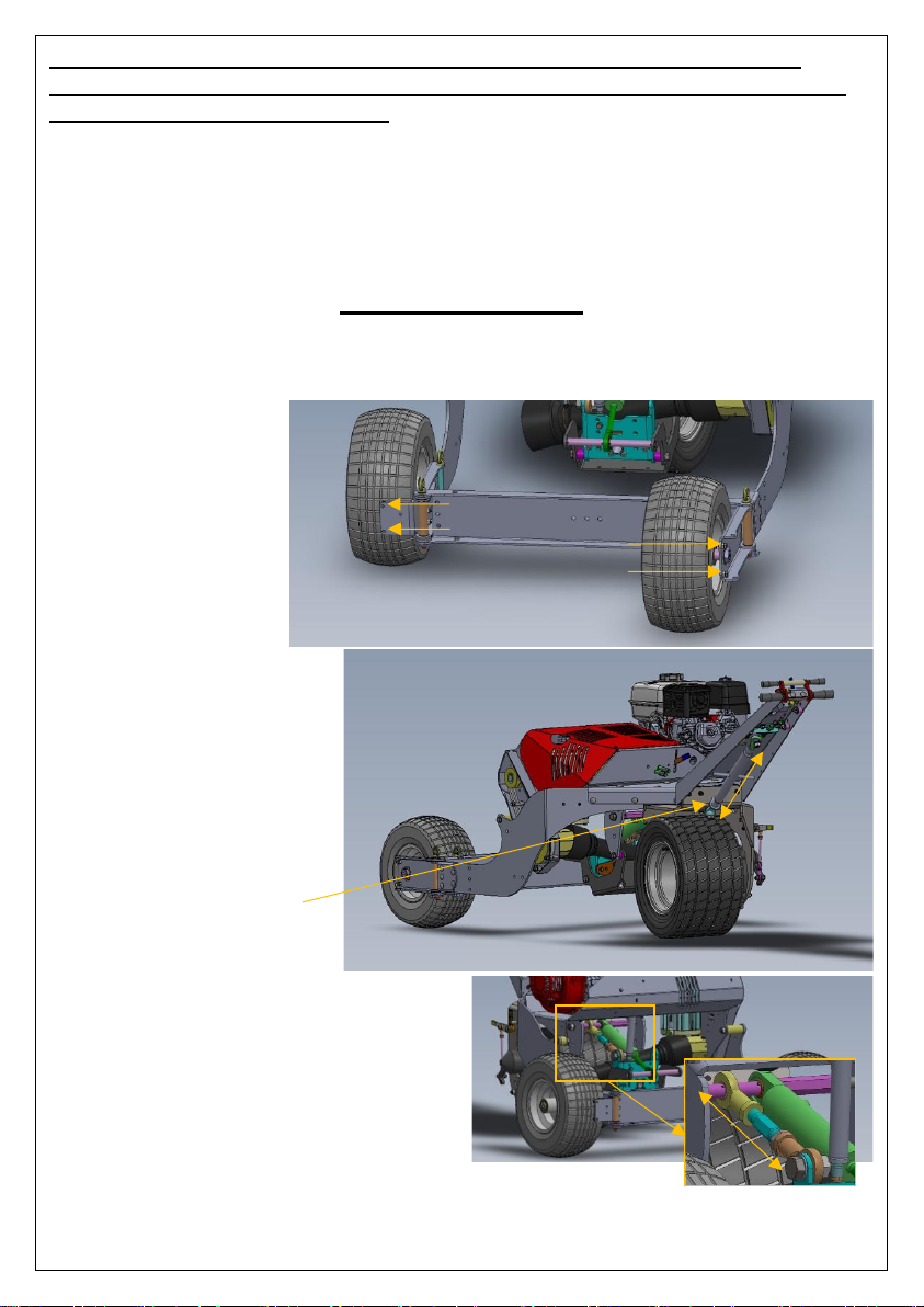
12. The rear wheels of the STrac 700 will always need to be placed beside the
machine when used in undulated areas.
13. The rear wheels of the STrac 700 can only be used behind the machine to
pass a gate or work close to a fence or wall. It is forbidden to use the
rear wheels behind the STrac 700 in undulated areas as the machine
could tip over.
14. Always apply the STrac 700’s handbrake when parking on slopes and
during transport on a trailer.
15. Make sure to always close the fuel valve on the engine, during transport
and long storage.
16. Maintain a logbook of all repairs on the MAREDO ST.
17. Be aware that changes made at the MAREDO ST, could release the
manufacturer from any safety regulations. The machine should be
homologated by the party who made the changes.
Always follow the safety instructions as described on the safety decal:
4 mtr/ 12 ft 4 mtr/ 12 ft

5
5.0 First start and first use
After first unpacking (See Separate MAREDO ST unpacking manual) it is important
to first check the STrac 700 before starting it for the first time:
5.1 First checks and engine start
5.1.1 Check if all protection covers are in place and undamaged.
5.1.2 Check if the engine oil level is correct. This can be checked by pulling out
the grey oil level stick which is located on the front of the HONDA engine (see fig.
1). Oil level should be between the marks.
5.1.3 Check if the hydraulic oil level is correct. This can be checked by pulling out
the oil level stick in the hydraulic tank. Make sure the STrac 700 stands on a flat
and level surface. This dipstick is easy to reach through the hole in the top cover.
The oil level should be between the bottom and top mark. NEVER START THE
ENGINE WHEN THE OIL LEVEL IS TOO HIGH OR TOO LOW. Drain oil when the oil
level is too high or fill with extra oil when the level is too low. See 2.0 Technical
specifications for the correct oil.
5.1.4 Check if the PTO lever is in the top position: O (see fig. 2) PTO OFF
5.1.5 Take all needed safety precautions before and during filling the gasoline
tank. Make sure not to spill gasoline over the engine. In case gasoline is spilled
over or beside the engine, the engine may not be started for 20 minutes.
Place the tank cap back right after fuelling.
5.1.6 Check and open the fuel valve on the engine (see fig 1.)
5.1.7 Put the motor switch to ‘ON’ (see fig 1.) and check if the Emergency Stop
on the handlebar is in its top position: ON
5.1.8 For a first (cold) start put the Choke lever on ‘Choke’ and Throttle on 40 –
50%
5.1.9 Pull engine cord gently towards you. Make sure not pull too hard to prevent
injuries. The engine should now start within 1 –2 pulls. For a Cold start leave the
Choke on for about 10 seconds and then switch the Choke off. The Engine should
now run smooth. (In case it does not please see 7.0 Trouble shooting). Give the
engine some time to warm up.

6
Figure 1: Engine and controls
5.2 ST head connection
5.2.1 After unpacking MAREDO ST heads (see Separate MAREDO ST
unpacking manual) they are placed on a MAREDO ST Trolley. Position the
MAREDO STrac 700 with the rear of the machine about 1 m/ 3’ in front of
the ST head which needs to be connected. The front of the ST head can
be recognized by the central connection pin which is located on the front.
Central connection pin
Anti-rotation bolt
Figure 2: ST head connection.
ON/OFF switch
Choke
ON OFF
ON OFF
Fuel valve
Forward < - > Reverse
+
-
Emergency stop
Handbrake
On
Off
PTO lever
-PTO always OFF
-PTO auto engage
-PTO always ON
Steering boom
height adjuster

7
5.2.2 Place the rear wheels in the position beside the STrac 700 as shown
in the image below. To do this the square pin needs to be pulled out. Next
the wheels can be put in the position besides the machine and re-locked
in place by the square pin see figure 3 below.
5.2.3 Remove the round pin which locks the rear ‘door’ bracket in place.
Either the left or right pin can be removed. Next the rear ‘door’ bracket
can pivot open giving all access to the hydraulic hitch. See figure 4.
Square pin for locking wheel
Round pin for rear ‘door’ bracket
Figure 3: Rear wheel and rear ‘door’ bracket locking pins.
Figure 4: Rear ‘door’ bracket in open position
5.2.4 Push the hitch control lever on the steering boom forward till it
clicks in float position. This makes that the hydraulic hitch can be moved
up and down by hand. Roll the ST head on the MAREDO ST trolley
forwards towards the STrac 700. Slide the central pin of the ST head into
the hole of the hydraulic hitch of the STrac. When the pin is inserted all
the way, it can be locked in place with an R-pin.
5.2.5 Connect the PTO to the ST head. Make sure to have the push pin of
the PTO facing down to be able to reach it and push it in.

8
NOTE: Never connect the PTO to the ST head with the engine
running. The engine must be switched off during connection and
dis-connection of ST heads.
5.2.6 Close the rear ‘door’ bracket and re-insert the locking pin. Lock this
pin in place with the secure pin. Check all connections and then start the
engine and lift the ST head by moving the hitch control lever on the
steering boom backwards. The ST head is now connected to the STrac
700.
6.0 Adjustments
Several adjustments can be made on the STrac 700. The most important
adjustments are described under this chapter.
6.1 Rear wheel
adjustments:
The adjustable end
stop bolts can be
adjusted to make the
square wheel pins fit
without slack.
6.2 Steering boom
adjustments:
The height of the
handlebar can be adjusted
underneath the handlebar.
The push rod can be
shortened or extended by
turning it.
Once set at the correct
height, lock in position with
the locking nut.
6.3 Top link
adjustments:
Standard the hitch of the STrac 700 is
adjusted correct. If needed the top link
of the hitch can be adjusted to create
another pitch. Loosen the locking nut
and turn on the top link. Next tighten
the nut again.
Adjustable
end-stop bolts

9
6.4 V-belt drive adjustments/
tensioning:
The PTO side
drive V-belts can
easily be
tensioned as
described here:
Do not over
tension!
6.5 Control
cable
adjustments:
When new, the
cables are set at
the correct length.
After a period of
use re-adjustment
might be needed.
Only adjust cables under the
steering boom. Only adjust the
outer cables in length and only
small steps at a time. Tighten
the outer cable nuts well after adjusting.
6.6 Handbrake
adjustment:
When new the
handbrake is
adjusted correct.
After a period of
use re-adjustment
might be needed.
Release the locking
nut on the
handbrake treaded rod and turn the adjuster to shorten the rod. Re-tighten the
lock nut again after adjusting.
6.7 Pump chain drive
adjustment/
tensioning:
To adjust the pump chain-
drive the whole engine
needs to be adjusted. This
can be done by adding or
removing filler plates
under the engine.
Loosen 2 x nuts on the inside
of the PTO cover. Tension
and re-tighten again.
Tensioner

10
7.0 Maintenance
On each STrac 700 an Hour/tach meter is located below the air filter.
Follow maintenance according to the interval as shown in the table below:
STrac 700
Before
each
use
Every
8
hours
Every
50
hours
Every
100
hours
Every
Year
Every
500
hours
Clean air filter
X
Replace air filter
X
Check engine oil
level
X
Change motor oil
X or
X
Check hydraulic oil
level
X
Change hydraulic
oil + replace filter
X or
X
Check tyre pressure
X
Grease PTO
X
Grease steering pin
X
Check and tension
V-belts
X
Check Emergency
stop
X
Check and re-
adjust handbrake
X
Check and tension
pump chain drive
X
7.1 Clean air filter: Remove the top nut of the plastic air filter housing.
Remove the air filter housing and remove the nut which holds the air
filter. Take the air filter out and clean it carefully with compressed air
blowing from the inside to the outside of the filter. Always replace
damaged air filters. Replace air filters once a year or every 500 hours.
7.2 Check oil level: see 5.1.2
7.3 Replenish motor oil: Take precautions to prevent oil spills. Carefully
remove the oil drain plug from the bottom of the engine. Let all oil drain
into an oil pan. When all oil is out, re-insert the drain plug and carefully
fill the engine with the correct engine oil (see 2.0 Technical specifications)
For checking the oil level see 5.1.2.

11
7.4 Check hydraulic oil level: see 5.1.3
7.5 Replenish hydraulic oil: Take precautions to prevent oil spills.
Carefully remove the oil drain plug from the bottom of the hydraulic by
using an Allen wrench. Remove the red top cover of the STrac 700 by
removing 6 bolts. Remove the plastic cap off the top of the hydraulic
tank. This can be done by removing three bolts. Now the hydraulic return
filter can be removed and replaced by a new filter. Mount the cover back
on the filter housing and mount the red STrac 700 cover back in place.
Let all oil drain from the tank into an oil pan. Re-insert the drain plug. Fill
the tank to a level just below the top mark on the oil level stick. Start the
engine and check for leaks. Let the engine run for 1 –2 minutes and then
stop the engine and check the hydraulic oil level again. If necessary, add
more oil.
7.6 Grease PTO: use a grease gun filled with EP2 grease. Turn the PTO
covers in a way that the grease nipple can be reached through this hole.
Grease 1 x grease nipple of the joint and 1 x grease nipple for the PTO
cover per side. Do not over grease!
7.7 Grease steering pin: Turn the steering boom all the way left or
right. Look straight from the front into the gap between the front wheel
frame and central frame. Here you can see the grease nipple positioned
on a bushing. Grease this nipple. Do not over grease!
7.8 Check and tension V-belts: There are in total 5 V-belts in the drive
lines of the STrac: three for the PTO clutch and two for the side drive.
7.8.1 Check the triple PTO clutch V-belts: Remove the red top cover
of the STrac 700. The three clutch V-belts can be found next to the
engine. If these V-belts start slipping, all V-belts need to be replaced.
This can easily be done by removing the engine. Take out the four bolts
and nuts and bend the motor over forwards to get the pulleys away from
under the V-belts and pump-chain. Replace the three V-belts and re
position the engine again in the opposite way. Make sure the drive line of
the chain and V-belts is aligned. Place the red top cover back in place.
7.8.2: Check the STrac 700 double side V-belt drive: Remove the
black side cover on the opposite side of the engine. It is held in place with
four nuts. Check the V-belt tension and re-tension if necessary. Re-
tensioning can be done on the bottom. Loosen up the two bolts that hold
the lower bearing house. Next use the tensioning nut on the STrac to
tighten V-belts. Re-tighten the bolts which hold the bearing house and
check if the V-belts are not adjusted too tight. Do not over tension the V-
belts as this may seriously damage the bearings.
7.9 Check and re-adjust cables: Cables control the throttle, the
hydrostatic forward-backward movements, and the hydraulic control
valve. It might be necessary to re-adjust these cables. These cables can
only be adjusted under the steering boom. Make sure to make small
changes at a time when adjusting the cable. When these controls have

12
improved the cables need to be screwed tight to prevent them from
coming loose.
7.10 Check and re-adjust handbrake: An engaged handbrake should
hold the STrac 700 always in place. The handbrake can be re-adjusted if
it becomes too loose. This can be done by loosening up the locking nut on
the connection rod between lever and wheel motor. Shortening this rod
means tightening the handbrake. Make sure to lock the locking nut back
in place after adjusting.
8.0 Storage
When the STrac 700 will be stored and un-used for a longer period please
make sure to follow the next steps:
8.1 Disconnect the ST head from the hitch of the STrac. Next raise the
hitch in the top position.
8.2 Drain all fuel from the tank and system by removing the drain plug
underneath the carburettor.
8.3 Check and set the correct tyre pressure.
8.4 Lower the steering boom to the lowest position. In this position the
steering boom rubbers are in the best position.
8.5 Place the STrac 700 in a dry spot and cover the STrac with a tarp to
protect it against dust and moisture.
When the STrac will be taken back in use, make sure to follow all steps as
described under 5.0 First start and first use.
9.0 Transport
9.1 Transport on an open trailer or open truck: Always close fuel
valve during transport (See figure 1).
Apply handbrake.
Reduce the working depth of the attached ST head to 0 and lower the
head onto the MAREDO ST trolley.
Always use a minimum of two straps for securing the ST machine for
transport. Connect the straps to the central frame of the STrac and not on
the handlebar.
9.2 Transport in a closed trailer or closed van/truck: Always close
fuel valve during transport (See figure 1). Drain fuel system (see 8.2)
Apply handbrake.
Reduce the working depth of the attached ST head to 0 and lower the
head onto the MAREDO ST trolley.
Always use a minimum of two straps for securing the ST machine for
transport. Connect the straps to the central frame of the STrac and not on
the handlebar.

13
10.0 Trouble shooting
Problem:
Possible cause:
Solution:
Engine does
not start.
Fuel tank empty.
Engine oil level too low.
Emergency stop engaged.
Broken spark plug.
PTO engaged during start.
Refuel.
Add engine oil.
Disengage Emergency stop.
Replace spark plug.
Dis-engage PTO.
Engine runs
poor.
Fuel tank nearly empty.
Wrong fuel in fuel tank. (see 2.0
for correct fuel)
Choke still engaged.
Clogged air filter.
Contaminated fuel system.
Stop and refuel.
Stop, drain fuel, and refuel.
Disengage choke.
Clean or replace air filter.
Drain and clean fuel system.
PTO does not
engage.
PTO lever not in the correct
position.
V-belts need to be re-tightened.
Put the PTO lever in the correct
position.
Re-tighten or replace V-belts.
STrac 700
does not drive
or lift the
hitch.
Broken chain drive.
Hydraulic oil leak.
Hydraulic oil level too low.
Replace chain and sprockets.
Stop, check for leaks, and repair
the leak.
Stop and fill hydraulic tank to the
correct level.
STrac 700 is
hanging to
one side.
Unequal tyre pressure.
Check tyre pressure.
STrac 700
does not move
forwards or
backwards
Handbrake still engaged.
Wheel stuck.
Hydraulic oil level too low.
Dis-engage handbrake.
Check if front wheel can rotate free
and remove obstacle(s).
Check hydraulic oil level.
STrac 700
vibrates
Loose components.
Clogged ST head.
Check and repair loose parts.
Clean ST head and reduce working
depth of ST head.
Engine is
stuck and
does not
rotate
PTO clutch still engaged.
Dis-engage PTO clutch.
Square
(rear)wheel
locking pin
does not fit
correct in the
holes.
Wheel bracket stop bolts not
adjusted correct.
Wheel turned while ST head is
not in float position.
Brackets not aligned.
Adjust the stop bolts.
Lower ST head and try again.
Push gently against the bottom of
the rear wheel or pull on the
bottom of the side leg to align the
holes.
Round pin for
locking rear
‘door’ bracket
does not fit
Brackets are not aligned
Push or pull the rear ‘door’ bracket
gently left and right until the holes
align. Or lift the rear wheel a little
to let holes align.
STrac 700 is
unstable in
undulated
areas
Wheels are in the rear position
Position wheels beside the machine

14
11.0 Options manual: ST170 FlexFraze-Mower
The MAREDO ST170 FlexFraze-Mower is designed as a light renovation head. Be
careful not to overload the MAREDO STrac 700 while using the ST170 head.
11.1 First start: After connecting the ST170 to the STrac 700 (See 5.2 ST head
connection) It is important to start always start at a working depth adjusted at 0
mm. Working depth can be adjusted by the two quick adjusters on the front
roller. Actual adjusted working depth can be checked by reading the depth
indicator decals on the front of the ST head. Working depth can be increased
gently until the desired result is accomplished.
11.2 Lock ST head: The ST170 can be locked in two ways:
11.2.1 Lock left to
right rotation pivoting
around the central
connection pin:
Locking bolt in position A
= fixed position.
Locking bolt in position B
= flexible position, ST
head can pivot around
central connection pin.
11.2.2 Limit forward
to backwards pivoting:
Option A: 2 x pushrods.
Standard B: 1 x locking strip with adjustable
hole position.
11.3 Check chain drive: After the
first 8 working hours the side chain
drive needs to be checked and re-
adjusted if needed. After that, every
100 hours the chain drive needs to be
checked.
To tension the chain first loosen the
two nuts ‘A’ on the inside of the PTO
cover. Next use tensioner ‘B’on the
underside to tension the chain by
moving the whole top sprocket tensioning assembly upwards. Tension till the
chain can be pushed in 5 mm/ 0.2”. If the top sprocket tensioning assembly is in
the top position and the chain is still too loose, re-adjust the sprocket tensioning
assembly all the way to the bottom and check by folding the chain if it can be
shortened with one chain link. When possible, remove one chain link and re-
tension.
11.4 Maintenance: Clean and check for broken or loose parts. Only use original
MAREDO spare parts. Always clean with low pressure water or compressed air.
Never use a high-pressure washer.
A
B
A
A
B
A
A
B

15
12.0 Options manual: ST200 Flex-Verticutter
The MAREDO ST200 Flex-Verticutter is a high quality verticut-/ scarification head.
Be careful not to overload the MAREDO STrac 700 while using the ST200 head.
12.1 First start: After connecting the ST200 to the STrac 700 (See 5.2 ST head
connection) Working depth can be adjusted by the two quick adjusters on the
front roller. Actual adjusted working depth can be checked by reading the depth
indicator decals on the front of the ST head. Working depth can be increased
gently until the desired result is accomplished.
12.2 Lock ST head: The ST200 can be locked in two ways:
12.2.1 Lock left to
right rotation pivoting
around the central
connection pin:
Locking bolt in position A
= fixed position.
Locking bolt in position B
= flexible position, ST
head can pivot around
central connection pin.
12.2.2 Limit forward
to backwards pivoting:
Option A: 2 x pushrods for optimal flexibility.
Option B: 1 x locking strip for reducing
flexibility.
12.3 Check chain drive: After the
first 8 working hours the side chain
drive needs to be checked and re-
adjusted if needed. After that, every
100 hours the chain drive needs to be
checked.
To tension the chain first loosen the
two nuts ‘A’ on the inside of the PTO
cover. Next use tensioner ‘B’ on the
underside to tension the chain by
moving the whole top sprocket tensioning assembly upwards. Tension till the
chain can be pushed in 5 mm/ 0.2”. If the top sprocket tensioning assembly is in
the top position and the chain is still too loose, re-adjust the sprocket tensioning
assembly all the way to the bottom and check by folding the chain if it can be
shortened with one chain link. When possible, remove one chain link and re-
tension.
12.4 Maintenance: Clean and check for broken or loose parts. Only use original
MAREDO spare parts. Always clean with low pressure water or compressed air.
Never use a high-pressure washer.
A
B
A
A
B
A
A
B

16
13.0 Options manual: ST210 VibeSpike-Aerator
The MAREDO ST210 VibeSpike-Aerator is a vibratory spike aerator. The vibration
of the spikes breakes compaction.
13.1 First start: After connecting the ST210 to the STrac 700 (See 5.2 ST head
connection Working depth can be adjusted by the two quick adjusters on the front
roller. Actual adjusted working depth can be checked by reading the depth
indicator decals on the front of the ST head. Working depth can be increased
gently until the desired result is accomplished.
13.2 Lock ST head: The ST210 can be locked in two ways:
13.2.1 Lock left to
right rotation pivoting
around the central
connection pin:
Locking bolt in position A
= fixed position.
Locking bolt in position B
= flexible position, ST
head can pivot around
central connection pin.
13.2.2 Limit forward
to backwards pivoting:
Option A: 2 x pushrods for optimal flexibility.
Option B: 1 x locking strip for reducing
flexibility.
13.3 Check V-belt drive: After the
first 8 working hours the side V-belt
drive needs to be checked and re-
adjusted if needed. After that, every
100 hours the belt tension needs to be
checked.
To tension the V-belts first loosen the
two nuts ‘A’ on the inside of the PTO
cover. Next use tensioner ‘B’ on the
underside to tension the V-belt by
moving the whole top pulley tensioning assembly upwards. Tension till the belts
can be pushed in 5 mm/ 0.2”. Do not over tension the belts as it may
seriously damage the drive line.
13.4 Maintenance: Clean and check for broken or loose parts. Only use original
MAREDO spare parts. Always clean with low pressure water or compressed air.
Never use a high-pressure washer.
A
B
A
A
B
A
A
B

17
14.0 Options manual: ST418 VibeDisc-Seeder
The MAREDO ST418 VibeDisc-Seeder is a
disc overseeder. Vibratory discs pre-cut
slits. Smaller discs placed in a V-shape
open the slit and allow seed to drop into
the slit.
14.1 First start: After connecting
the ST418 to the STrac 700 (See
5.2 ST head connection Working
depth can be adjusted by turning
the top link on top of the ST418
head. Extending the top link will
decrease the working depth. Shortening the top link will increase working depth.
Make sure to lock the top link with the locking nut after adjusting.
After the depth adjustment seed dosing rate can
be set. This can be done by changing gear
reductions in the gearbox beside the rear
roller. The highlighted green gears in the
image on the right can be interchanged for
other gear reductions. A dosage decal on
the inside of the gearbox shows which
dosage amount comes with which gear
reduction. The extra gears are standard
supplied.
14.2 Lock ST head: See 11.2 Lock ST head
14.3 Check V-belt drive: See 13.3 Check V-belt drive.
14.4 Maintenance: Clean and check for broken or loose parts. Only use original
MAREDO spare parts. Always clean with low pressure water or compressed air.
Never use a high-pressure washer. Always remove seed from seed box after each
use. Clean funnels with compressed air blowing through the funnels.

18
15.0 Spare parts
Part number:
Description:
5011225
Honda air filter
5013200
Spark plug
4711906
Hydraulic return filter
999903
5W50 Engine + Hydraulic oil

19
Notes:
_
This manual suits for next models
1
Table of contents
Popular Lawn Mower manuals by other brands

WEIBANG
WEIBANG WB436HKL AL Operator's manual

Sealey
Sealey GL112 instructions

AL-KO
AL-KO Solo Comfort Translation of the original instructions for use

AL-KO
AL-KO Combi care 38p comfort operating instructions

Snapper
Snapper 2800 GT Series, 1800 GT Series Operator's manual

Texas A/S
Texas A/S 5150 TR/WE user manual