Hover Mower Operator’s Manual
Maruyama U.S. | 4770 Mercantile Dr. Suite 100 | Fort Worth, TX | 76137
Safety Precautions and Training
Understand the operation of all controls and
learn how to stop the engine and mower
quickly in case of emergency. Make sure the
operator receives adequate instruction
before operating this unit.
When instructions refer to the left or right
side of the unit, it means as if the operator is
standing behind at the normal operation
position.
1.
Read all information contained in this
manual and the engine manual carefully. Be
thoroughly familiar with the controls and
proper use of the equipment.
2.
Always use proper PPE including at
minimum safety glasses, hearing
protection, and proper footwear.
3.
Never allow children to operate mower.
4.
Never operate this unit when you are tired, ill
or under the influence of alcohol, drugs or
medication.
5.
Never try to mow across excessively steep
terrain. On inclines, keep the unit in front /
below and maneuver in a pendulum motion.
6.
Keep area of operation clear of all
persons, particularly small children
and pets.
7.
Never operate the mower without proper
guards / shields in place.
8.
Thoroughly train anyone using the mower.
Make sure all mower operators know the
safety, operating and maintenance
procedures.
9.
Never leave the mower unattended with the
engine running.
10.
Mow only in daylight or in good artificial light.
11.
Always be sure of your footing. Keep a firm
hold on the handle and never run with the
unit.
12.
Do not operate mower when barefoot or
wearing open sandals. Always wear
substantial footwear and pants or slacks
that cover your legs when operating
mower.
13.
Material may ricochet back toward the
operator. Do not operate over gravel
surfaces.
Preparation and Inspection
1.
Thoroughly inspect the area where mower is
to be used and remove all stones, sticks, wire,
bones and other foreign objects which might
be thrown. Never operate the unit over gravel.
2.
Check fuel before starting engine. Do not
fill gasoline tank indoors or when engine is
running. Wait until engine has been
allowed to cool for several minutes. Clean
off any spilled gasoline before starting
engine.
3.
Make sure the unit is on a flat level
surface before starting engine.
4.
Inspect the unit to verify the controls, safety
switches, and handles are assembled properly.
Do not operate unless they are functioning
properly.
5.
If the machine should start to vibrate
abnormally, stop the engine, and check
for the cause immediately.
6.
Use care when loading or unloading the
machine into a trailer or truck.
7.
Never operate machine in an enclosed area.
8.
Keep all nuts and bolts tight to be
sure the equipment is in safe
working condition.
9.
Never tamper with safety devices.
Check their proper operation regularly.
10.
Keep machine free of grass, leaves, or other
debris build-up – especially the recoil starter
area of the engine. Clean up oil or fuel
spillage and remove any fuel-soaked debris.
Allow machine to cool before storing in an
enclosed space.
11.
Never make any adjustments or repairs
with the engine running. Disconnect the
spark plug wire to prevent unintended
starting.
12.
Do not change the engine throttle setting
or over- speed the engine.
13.
Maintain or replace safety and instruction
labels, as necessary.
14.
If gasoline is spilled, do not attempt to start
the engine but move the machine away from
the area of spillage and avoid creating any
source of ignition until the gasoline vapor has
dissipated.
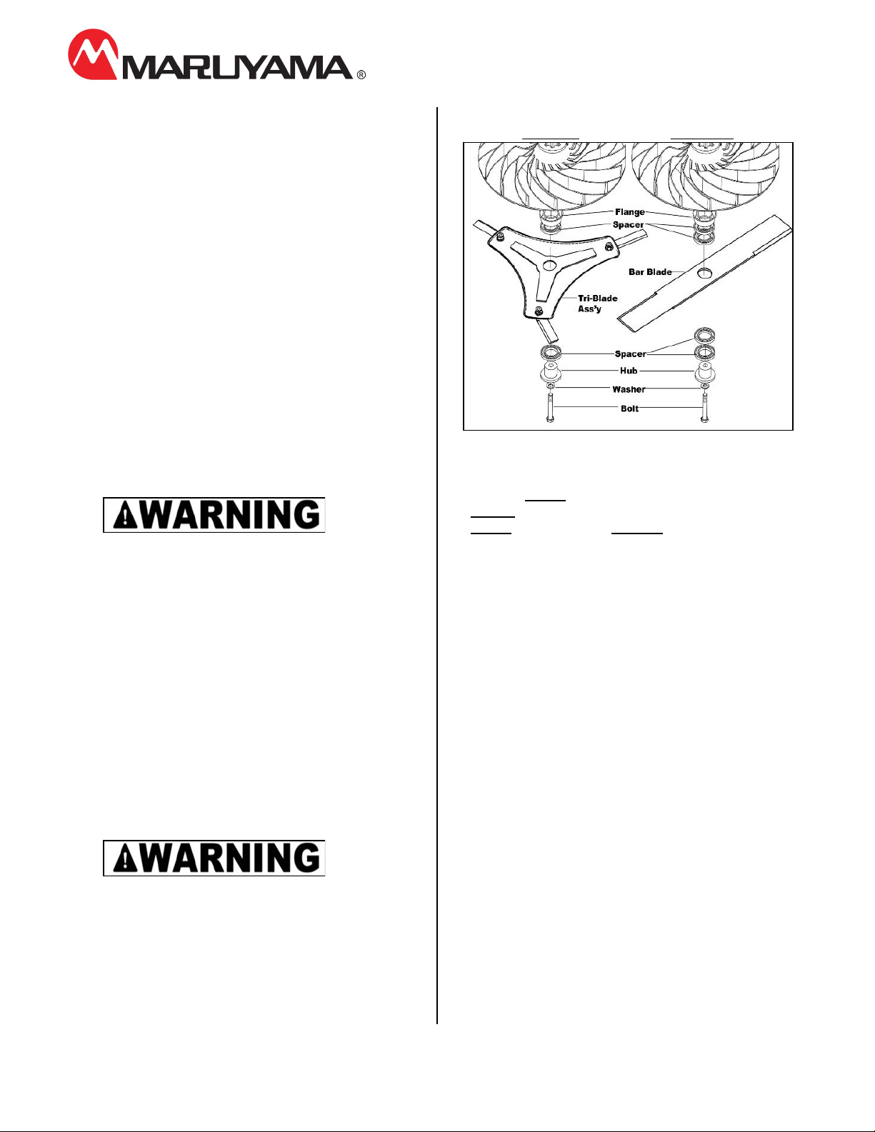
15.
Before using, always visually inspect to see
that the blade(s), bolts, and spacers are not
worn or damaged. Replace a worn or
damaged blade(s).