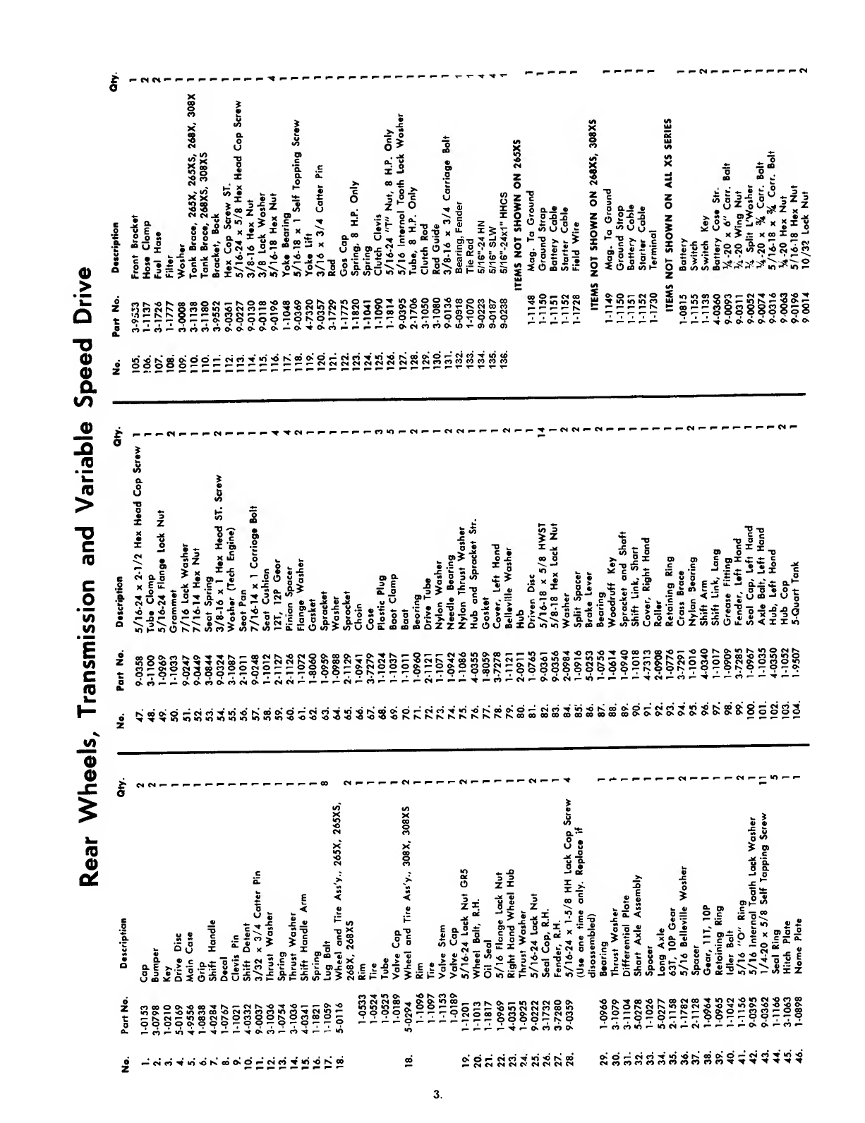
McDonough Power Equipment 265X User manual

Operator's
Manual
THANK
YOU
FOR
BUYING
A
SNAPPER
PRODUCT!
We
have
designed
and
built
this
machine
with
utmost
care,
and
it
is
intended
to
give
you
long
and
satisfactory
service.
Any
mechanical
device
can
be
potentially
dangerous
if
not
used
properly.
No
accident
prevention
program
can
be
successful
without
the
wholehearted
co¬
operation
of
the
person
who
is
directly
responsible
for
the
operation
of
the
equip¬
ment.
Study
this
operator's
manual
to
learn
the
operation
of
the
controls
and
observe
all
safety
precautions.
Only
use
this
machine
for
the
purpose
it
is
intend¬
ed.
By
following
these
instructions
and
safety
precautions
you
should
enjoy
the
long
and
trouble
free
operation
you
expect.
Snapper
Comet
Riding
Mower
MODELS
265X
-
265XS
-
268X
-
268XS
308X-308XS
SNAPPER
MOWER
GUARANTEE
All
Snapper
Mowers
are
guaranteed
for
normal
use
to
the
original
purchaser
against
defec¬
tive
workmanship
and
moterial.
This
guarantee
extends
for
one
year
from
purchase
dote
on
mowers
not
used
commercially,
and
for
one
month
on
mowers
that
are
used
commercially.
We
will
replace
or
repair
without
charge
any
port
or
parts
returned
to
us
during
the
guarantee
period,
with
transportation
charged
prepaid,
that
our
inspection
shows
to
have
been
defective
in
workmanship
or
material
when
shipped
from
the
factory.
This
guarantee
is
void
if
the
ports
in
question
hove
been
altered
or
damaged
by
accident,
abuse
neglect,
improper
odjustment,
lack
of
lubrication
or
normal
wear.
This
guarantee
does
not
cover
engines,
tires,
tubes,
batteries
and
belts
which
ore
guaranteed
separately
by
their
manufacturers.
No
other
guarantee,
expressed
or
implied,
is
mode
by
the
Compony
which
retoins
the
right
to
change
specifications
without
notice
or
obligation.
WARNING:
Use
of
replacement
parts
other
than
genuine
Snapper
parts
may
impair
the
safety
of
your
mower
and
may
void
our
warranty.
IMPORTANT:
This
guarantee
is
void
unless
the
guarontce
card
attached
is
filled
out
com¬
pletely
end
moiled
to
the
Factory
within
10
days
of
the
date
mower
was
purchased.
IT
IS
THE
POLICY
OF
McDONOUGH
POWER
EQUIPMENT,
INC.
TO
IMPROVE
ITS
PRODUCTS
WHEN¬
EVER
IT
IS
POSSIBLE
AND
PRACTICAL
TO
DO
SO.
WE
RESERVE
THE
^'GHT
TO
MAKE
ADD
IMPROVEMENTS
AT
ANY
TIME
WITHOUT
INCURRING
ANY
OBLIGATION
TO
MAKE
SUCH
CHANGES
ON
PRODUCTS
MANUFACTURED
PREVIOUSLY.
McDONOUGH
POWER
EQUIPMENT,
INC
McDONOUGH,
GA.,
U.
S.
A.,
30253
REV
1,
11/71
MANUAL
#06052


Rear
Wheels,
Transmission
and
Variable
Speed
Drive
t
—
«
«H
o
.8
S
£
I
■
£
Si
'
•c
“
u
J
-
o
c
c
o
:
>
o
o
±
.
•
>
K
H
*0
.
i
ZlO
,5
J
J
“••
.s
J
o^
O
,
;
o.«
n^l==|:s”^
'
«~~"2l2*“-ooora*‘<o‘<>“>*
I
u
tS
iS'^u
OT^iS
u«rifflP3iB5>
J
O
O-i
«
z
(5
2-gS
5
-
«/>
U
u
—
*
°-0
»
w
g
^
o
S
?;
o
i;
Q
^
O
iS
*'>
o
^
“S
o
u
Z
0
Os
«>
_
>
«
>•
J
2
5
0
>>
•
0
«
.E
J
:
X
^
.t:
X
e
«||
iS8«8;
1.^
iHB^isiiisiiiiiippliiiiiiiiiiii
jj^^^j^pi^^c^eooKOKO^OKCx^CK^OKo*-*-*-
—
—
d.w«o<nOKio-»-<AOT<A
^
^
o
(N
o
S
JJJ
X>
*0
*0
CO
JJJ
•O'oetjQo^ex'^'Ocj^^
.-lOeoNO^
—
xjhs^jgo-j-
g::::
8
§
8
8
8
S
8
5
8
•
«o
*0
rs.
I
2
S
S
3
!
:::«”
2
:
22
S
:
228
s
a
S
5
S
S
f
5
S
?
i
8
s
S
8
S
SS
c*
-“
£
=
S
5
sz
«
Q.§
^
S
X
E
u.
^
X
o
^
SoS
E
°2,
•
<0
E
'C
<0
^
jQ
•-
0^»-
lo
h-
«o
O
rs
hs
I
UJ
o
w
^
c
8
8
'“.2
0
*5
.
»
o
0
0
t*
.
^
^
•
«x
.
f
>
vj
rs
v>
•-^
I
655
«
=
15
15
==i5
.
0
)>V
o_c
ooo
>.
•
iSx;;
•
-cts'Sa
i
>o
^
^
it
»5g2«
Sx«
S;
“i
»
"
•
aX
c
—
oo**/)^
.
"
o*^
o
rt*5
*
•«
S'^S'x'a
o
oT
3‘C'^*>'a2
8>
jZZZlOo«XOioio>»n«o«o>
'•
■
to
..
»
u.
Q.
*:.;
.
o
o
I
V
k.
u
CO
'
2
•
o
^
«
2
c
p
-=
•
«.8
i
•
!j;?8ig;sSjS5!iS5iSS;S:5S53SS5gSS^KR;jRSP:f;S:g53SS2
2fe£S§5:SS5gSB:SS8oSSS
o
•
"c
A
s
O
Q
u
X
W
3
^
^
.Z
^
u
flo
^
o
<
O
«/)
I
_
d»
u
.o
^
^
£
•
>
Ox
D
%/)
5
“O
><
*=
2
X
oS
o>
a
t;
'
c
5
X
w
Q>J=
CO
:
a
D
>
X)
7
V>
^
>
CN
o>
®
<
o)
.s
—
,
.E
S
0'
ij
o
t/)
o
Q
j
_•
CN
_
a>
V
^
e
2-§-5^
.1
2*0
‘
=
5'
c
i
0
8
3
3
)
IX
2
x>
8
.^
^
X
z
OOOOO.X)OO^K^C.|^*C^-
0
^
;
-
5
;'0
S?£?S"srgg
3
3
5
i
2
r
::Sj;
5
qgj':jgg
•o<>‘*-x>«o<noo«ocs<
2
J
’J
5
S
^
2
3
SS
^
oooog'-'-'
7
o
g
o
o
o
5
«
0
'wrsCNco
—
fscx
—
•o»cHhs
0
2
2
®
C
5
®
S
2
*
®°rt
■
oooooHOOO^oo^o-
70^'70
^^^,-0
—
.-.-.-^^
.
vvvv.^.
’OC>K'X'oo'ON.oocxoo'^x>cc'
0
«
oeN^c
2
o
p
^Ko”csrsioooex«'
02
'
00
j;
0
'
0
'
00
^
0
'
0
'
-cxocNt-rN.»-^^o^
2
5
2'"®2
o^-*-
0
'
-o^'
7
^
o
o
^
'
700
'
7'70
*-‘c«ir>^‘
0
'
OKooO‘
0
^
<
xr>^>o>©rseo
o»o^cx<^'^‘n'ON.«
#»<x<xcxcxr>cx<x<x<N
o^O'—cxfoV*o<>rs.
5
5
^
o
^
2
522!03
cscortocoo<*)co<^oco^^^^^^^
3

Spindle,
Cutter
Unit
and
Lift,
26",
30"
Snapper
Comet
No.
Part
No.
Description
Qty.
No.
Port
No.
Description
Qty.
No.
Part
No.
Description
1.
9-0302
1/4-20
X
3/8
Self
Tapping
4
32.
1-8069
Cutter
Bar,
30"
Comet
1
40.
4-7318
Front
Lift
Arm
2.
1-8040
Spindle
Cover,
26'^
Comet
1
32.
1-8068
Cutter
Bar,
26"
Comet
1
41.
4-7324
Rail
Str.,
30"
Comet
2.
3-7296
Spindle
Cover,
30^'
Comet
1
33.
9-0392
1/2-20
X
1
HHCS
HT.
2
41.
4-7317
Rail
Str.,
26"
Comet
3.
1-0027
Jam
Nut
1
34.
9-0278
5/8
Jam
Nut
1
42.
4-7254
Idler
Handle
4.
1-0935
Washer
14
35.
4-7323
Deck,
30"
Comet
1
43.
1-0681
Grip
5.
1-0787
Spindle
Pulley
1
35.
4-7325
Deck,
26"
Comet
1
44.
1
-0737
Roll
Pin
6.
3-0817
Brake
Drum
1
36.
1-0739
Retaining
Ring
3
45.
1-0741
Tolerance
Ring
7.
5-0280
Brake
Shoe
Ass^y.
1
37.
9-0041
Cotter
Pin
1
46.
2-0880
Idler
Link
8.
9-0161
3/8-24
X
1-3/4
HHCS
1
38.
2-0882
Support
Rod
1
47.
1-0750
Spring
9.
1-1029
Idler
Pulley
3/8
Bore
1
39.
9-0365
Cotter
Pin
2
48.
3-0813
Idler
Arm
10.
9-0122
3/8
Washer
9
49.
2-7184
Spindle
Qty.
Comet
Comet
11.
3-0982
Restrictor
12.
9-0289
3/8-24
L'Nut
13.
1-0740
Retaining
Ring
14.
1-0736
Clevis
Pin
15.
1-0735
Clevis
16.
2-1157
Timing
Rod.
30'
16.
2-1135
Timing
Rod.
26'
17.
1-0996
Ring.
26“
Comet
17.
1-0996
Ring.
30"
Comet
18.
1-0684
Grip
19.
4-0385
Chain
Arm.
R.
H.
19.
4-0386
Chain
Arm.
L.
H.
(Not
Shown)
20.
9-0183
5/8
Washer
21.
9-0364
5/32
x
1
Cotter
Pin
22.
4-7295
Lift
Handle
23.
4-7319
Rear
Lift
Arm
24.
9-0055
1/4
SAE
Washer
25.
1-1074
Spring.
30"
Comet
25.
1-1010
Spring.
26"
Comet
26.
9-0292
3/8-24
x
3/4
HHCS
5-0195
Spindle
Assembly
27.
4-0273
Housing
28.
1-0696
Bearing
29.
1-0817
Alemite
Fitting
30.
3-1182
Spacer
31.
9-0393
1/2-20
Hex
Hd.
Lock
Nut
1-1051
1-0749
3-7334
3-1183
3-1184
6-0173
1-1758
9-0053
9-0101
9-0095
1-1763
1-0819
1-1812
Retaining
Ring
Belt
Deflector
Washer
Blode
Holder
Height
Plate
and
Decal
Kit
Decal
1
/4
Int.
Tooth
L'Washer
1/4-28
X
3/4
HHCS
1/4-28
Hex
Nut
Fender
Washer
Washer
"O"
Ring
4

Front
Wheels,
Front
End
and
Steering
No.
Part
No.
Dotcriplion
Oty.
1.
4-9333
Front
Axlo
1
2.
1-0776
Rotaining
Ring
2
3.
1-1020
Foot
Pod
2
4.
1-0746
Rotaining
Ring
2
3.
1-0986
Boaring
4
6.
1-0933
Warhor
1
7.
1-1100
Boaring
Half
4
8.
4-0361
King
Pin,
RH
1
8.
4-0362
King
Pin,
IH
(Not
Shown)
1
9.
9-0123
3/8
SAE
Washor
4
10.
9-0337
3/16
X
%
Cottor
Pin
4
11.
3-1038
Dust
Cap
2
12.
3-0618
Whool
Asi'y.,
268X,
268XS,
308X,
308XS
1-0819
Rim
and
Hub
1-0820
Tiro
1-0821
Tube,
Mfrs.
Option
1-1807
Ball
Bearing,
1%
O.
D.
1
0909
Grease
Fitting
1-0189
Valve
Cap
12.
3-0179
Wheel
Assy.,
263X,
263XS
1-0819
Rim
and
Hub
1-0820
Tire
1-0821
Tube,
Mfrs.
Option
1-0370
Bearing,
1%
O.
D.
1-1727
Bearing,
1
%
O.
D.
1-0909
Grease
Fitting
1-0189
Valve
Cap
Note:
When
ordering
tire
specify
tube
or
tubeless.
When
ordering
bearing
specify
O.
D.
13.
1
-0933
Spacer
14.
9-0364
3/32
x
1
Cotter
Pin
No.
Part
No.
Doecription
Oty.
13.
1-1022
Hub
Cap
2
16.
3-1179
Felt
Washer
2
17.
4-0344
Steering
Shaft
1
18.
3-1038
Tie
Rod,
RH
1
19.
3-1037
Tie
Rod,
LH
1
21.
9-0033
M
Internal
Tooth
L'Woihor
2
22.
4-7327
Ptdal
1
23.
1-1046
CobU,
30^'
Snoppor
Comot
1
23.
1-1047
CabU,
26**
Snoppor
Comot
1
24.
1-0690
Shim
Woshor
2
23.
9-0093
%-28
Hox
Nut
2
26.
9-0109
Hondlo
Scrow
2
27.
3-9340
Stooring
Whool
1
1-1091
Docol,
26"
Comot
(Not
Shown)
1
1-1092
Docoly
30"
Comot
(Not
Shown)
1
1-0994
Doeot,
"Snoppor"
(Not
Shown)
1
28.
1-10B9
Podot
Pod
1
29.
1-1099
Booring
Half
4
30.
1-1079
Spring
Woshor
1
31.
1-1078
Shouldor
Bolt
1
32.
1-1080
Grip
1
33.
3-1120
Broko
Lovor
1
34.
1-1130
Throttio
Control
1
33.
1-1131
Pioto
1
36.
9-0363
10/24
X
%
WFCS
ST
2
5

Assembly,
OperaHon,
Service
Manual
and
Parts
List
SNAPPER
COMET
26"
&
30"
1.
ASSEMBLY:
A.
Remove
top
and
sides
from
crate.
B.
Install
steering
wheel
using
two
(2)
1
/4
x
1%
bolts.
C.
Cut
shipping
straps
and
remove
mower
from
crate
bottom.
D.
On
some
models
it
is
necessary
to
reconnect
steering
link
which
has
been
disassembled
due
to
crating
size
limitations.
E.
FILL
ENGINE
WITH
FUEL
AND
OIL.
2.
GENERAL
OPERATION:
A.
S
TART
ENGINE:
1.
Make
certain
shift
handle
is
in
neutral
and
cutter
unit
out
before
attempting
to
start.
2.
Refer
to
engine
manual
for
throttle
control
Instructions
for
the
type
used.
3.
If
engine
is
also
equipped
with
electric
starter,
refer
to
engine
manual
for
starting
procedure.
The
starter
switch
is
located
to
the
rear
of
the
battery.
B.
F
ORWARD
MOTION:
1.
Disengage
clutch
and
apply
brake
by
depressing
pedal
to
the
end
of
its
travel.
NOTE:
Excessive
pedal
pressure
detrimental
to
easy
shifting.
2.
Move
shift
lever,
located
on
right
hand
side
of
seat,
to
the
low
speed
position
(No.
1)
and
slowly
release
clutch
and
brake
pedal.
3.
Speeds
may
now
be
increased
or
decreased
without
the
use
of
the
clutch
pedal.
4.
Never
start
by
moving
shift
handle
without
use
of
the
clutch
pedal
as
the
driven
disc
life
will
be
shortened.
5.
Always
begin
forward
motion
in
No.
1
speed
position.
C.
REVERSE
MOTION:
Follow
same
procedure
as
"B"
above,
however,
there
is
only
one
speed
in
reverse
and
shift
handle
must
be
held
in
reverse
position
at
the
end
of
the
slot.
D.
STOPS;
1.
The
mower
may
be
stopped
in
either
forward
or
reverse
motion
by
depressing
clutch
and
brake
pedal.
2.
Always
return
shift
handle
to
neutral
after
a
stop
is
made.
3.
As
a
safety
precaution,
if
stops
have
to
be
made
going
up
steep
inclines,
back
down
to
level
ground
to
re-start.
E.
CUTTER
UNIT:
1.
Cutting
height
is
adjusted
by
simply
changing
the
position
of
the
lift
handle.
There
are
different
positions
ranging
be¬
tween
1
and
4
inches.
2.
Cutter
engagement
is
accomplished
by
slowly
pulling
the
cutter
handle
to
the
rear
until
the
spring
loaded
idler
takes
over.
The
spindle
brake
is
automatically
released
or
applied
as
this
handle
is
shifted
from
the
"in"
or
"out"
position.
Cutter
engagement
or
release
may
be
accomplished
at
any
cutting
height
with
the
mower
moving
or
at
rest.
3.
A
DJUSTMENTS:
A.
C
LUTCH:
The
clutch
linkage
has
been
designed
so
that
with
inital
factory
adjustment,
the
driven
disc
wear
is
accommodated
throughout
its
useful
life.
Replace
disc
when
worn
to
1/32
—
1/16
inch
rubber
thickness.
Do
not
tamper
with
linkage
if
mower
does
not
pull
at
this
point.
Replace
driven
disc.
In
the
event
someone
tempers
with
the
factory
adjustment,
the
linkage
can
be
checked
as
follows:
1.
Remove
driven
disc
and
install
adjusting
gauge,
which
can
be
made
from
a
driven
disc
with
the
^'as
new"
radius
of
3
inches
on
half
the
circumference
and
a
2%
inch
radius
ground
on
the
other
half.
2.
Depress
clutch
pedal
and
shift
to
second
speed.
3.
Adjust
clutch
rod
guide
until
the
2%
inch
radius
clears
driving
disc
.005/.010
inch,
4.
Rotate
gauge
180
deg.
and
fully
depress
clutch
pedal
until
brakes
are
applied.
Check
to
see
that
the
3
inch
radius
clears
driven
disc
by
1
/32
inch
minimum
with
sliding
chain
case
pushed
lightly
against
yoke
lift.
This
assures
that
driven
disc
will
be
pulled
down
from
driving
disc
when
clutch
is
disengaged.
B.
C
LUTCH
AND
BRAKE
PEDAL:
Control
cable
should
have
slight
amount
of
slack
with
clutch
and
brake
pedal
released
and
with
shift
handle
in
neutral.
This
can
be
checked
by
seeing
that
the
clutch
rod
slides
to
the
rear
end
of
slot
in
the
clutch
rod
guide.
Adjust
by
shifting
cable
stops
as
required
through
keyhole
in
brake
pedal.
C.
P
ARKING
BRAKE:
To
apply
—
press
brake
and
clutch
pedal
down
firmly,
push
park¬
ing
brake
handle
down
clamping
brake
cable.
To
release
raise
handle.
D.
C
UTTER
DRIVE
BELT:
The
spring
loaded
idler
maintains
proper
belt
tension
throughout
the
effective
belt
life.
Adjust
main
tube
when
idler
pulley
causes
the
belt
to
rub
together
behind
the
spindle
pulley.
Main
tube
adjustment
Is
accomplished
as
follows:
1.
Loosen
clamp
under
seat
spring
and
pull
main
tube
forward
until
inside
surface
of
cutter
drive
belt
has
approximately
1"
running
clearance
measured
at
the
Idler
pulley
with
cutter
unit
engaged.
2.
Check
to
see
If
control
cable
has
a
slight
amount
of
slack
with
clutch
and
brake
pedal
released
and
with
shift
handle
in
neutral
discussed
in
"D"
above.
Belt
replacement
is
accomplished
as
'ollows;
1.
Remove
spindle
guard
cover
and
remove
belt
from
pulley.
2.
Stand
mower
on
end
(refer
to
"Storage")
with
shift
handle
in
neutral.
3.
Puli
belt
from
behind
drive
disc.
Reach
behind
slide
and
pull
clutch
rod
for
maximum
disc
clearance.
Roll
belt
between
drive
and
driven
discs.
Pull
belt
between
driven
disc
and
belt
guide
and
remove
from
transmission
case.
4.
Reverse
procedure
to
install
new
belt.
6

E.
C
UTTER
SPINDLE
REMOVAL:
If
it
is
necessary
to
remove
and
re-assemble
spindle
housing,
the
housing
must
be
plumbed
to
the
cutter
deck
to
obtain
an
equal
distance
between
the
blade
tip
and
deck.
This
is
accomplished
by
locating
the
housing
flange
correctly
to
the
deck,
using
the
clearance
holes
For
the
capscrews
for
alignment.
Tighten
securely
using
self-locking
nuts.
F.
DECK
ADJUSTMENT:
The
cutter
blade
has
been
factory
adjusted
for
1
inch
minimum
cutting
height.
After
a
period
of
time,
wear
in
the
linkage
may
require
re-adjustment.
Correct
procedure
is
as
follows
—
taking
all
measurements
to
the
same
blade
tip:
1.
Park
mower
on
level
and
even
floor
of
surface.
2.
Move
lift
handle
to
lowest
position
to
remove
spindle
cover.
3.
Adjust
blade
tip
cutting
edge
to
1
%
inch
at
rear
by
bending
the
swinging
chain
arms
of
the
rear
suspension
up
or
down
as
required,
maintaining
a
level
blade
side
to
side
as
this
is
adjusted.
4.
Swing
blade
tip
to
front
and
adjust
to
1
inch
by
adjusting
timing
link
that
connects
the
front
and
rear
lift
arms.
Shortening
this
link
turn
of
the
rod
end
raises
front
end
approximately
1
/8
inch.
5.
Turn
blade
to
point
to
the
front
and
rear
of
machine.
The
26”
and
30"
blade
should
be
at
least
V
2
”
higher
at
rear
than
the
front.
G.
TIRES:
1.
Inflate
front
tires
to
20
lbs,
2.
Inflate
rear
tires
to
25
lbs.
4.
BATTERY
INSTALLATION
(FOR
ELECTRIC
STARTER
ONLY):
A.
Service
battery
according
to
instructions
supplied
with
the
battery.
B.
Remov
2
battery
clamping
bracket
and
install
battery
under
left
hand
side
of
seat.
C.
Attach
battery
lead
to
battery.
Check
engine
manual
for
positive
or
negative
ground.
D.
Refer
to
engine
manual
for
operating
instructions
of
the
battery
charging
system
used.
5.
STORAGE:
The
mower
may
be
set
on
end
for
servicing
or
storage
within
the
following
limitations.
A.
For
electric
starter
units,
remove
battery
to
prevent
acid
leakage
and
subsequent
damage.
B.
Gas
tank
must
be
practically
empty
to
eliminate
fire
hazard.
C.
For
winter
storage,
always
drain
oil
and
gasoline.
Refer
to
engine
manual
for
proper
procedure
to
follow.
Oil
or
grease
any
parts
of
the
mower
subject
to
rust
or
corrosion.
6.
OPTIONAL
EQUIPMENT;
To
increase
the
usefulness
of
your
Snapper
Comet
Mower,
the
following
kits
may
be
obtained
as
Optional
Equipment;
6-0049
Tire
Chains,
16
x
4.80
—
8
Tires
6-0119
Tire
Chains,
16
x
6.50
—
8
Tires
6-0111
Leaf
Mulcher,
26"
6-0118
Leaf
Mulcher,
30"
6-0185
Snow
Plow
Kit
6-0110
Deluxe
Seat
6-0183
Grass
Catcher
Kit
6-0169
Steering
Wheel
Kit
6-0170
Wheel
Brake
Kit
SAFETY
PRECAUTIONS
Remember,
a
careful
operator
always
is
the
best
insurance
against
an
accident.
Study
your
operator's
manual—become
familiar
with
the
controls
and
how
the
mower
operates.
Learn
to
stop
the
mower
quickly.
Never
attempt
to
start
engine
unless
shift
handle
is
in
neutral
and
idler
handle
in
the
out
position.
For
forward
motion,
always
begin
movement
with
shift
handle
in
No.
1
speed
position.
Before
starting
clear
area
of
debris.
Operate
the
engine
at
the
slowest
speed
that
will
cut
satisfactorily.
Stop
and
check
for
breakage
and
repair
any
damage
after
striking
foreign
objects.
Mount
mower
from
left
hand
side,
opposite
the
discharge
chute.
Keep
hands
and
feet
clear
of
the
cutter
unit
at
all
times.
Do
not
operate
mower
with
guards
removed.
Disengage
cutter
and
stop
engine
before
dis¬
mounting.
Do
not
crank
or
operate
engine
where
exhaust
fumes
can
collect.
Never
allow
children
to
operate
the
Snapper
Comet.
Instruct
individuals
to
stay
away
from
the
mow¬
er
while
it
is
in
operation.
Do
not
let
others
ride
with
you
on
the
mower.
Give
complete
and
undivided
attention
to
the
job
at
hand.
When
mowing,
never
discharge
clippings
toward
windows
and
doorways.
Mow
only
in
daylight
or
in
good
artificial
light.
Be
extra
careful
when
working
on
hillsides
or
rough
ground.
Watch
out
for
holes
or
ditches
into
which
a
wheel
may
drop
and
cause
the
mower
to
overturn.
If
it
is
necessary
to
stop
when
going
up
steep
in¬
clines,
back
down
to
level
ground
to
re-start.
When
going
down
inclines,
keep
in
low
speed
with
clutch
and
brake
pedal
out
to
allow
engine
to
control
speed.
Fill
gas
tank
outdoors,
but
never
while
engine
is
running
or
while
engine
is
hot.
Avoid
spilling.
Always
use
an
approved
gasoline
can.
7

LUBRICATION
INSTRUCTIONS
FOR
SNAPPER
COMET
26"
&
30"
1.
Spindle
is
assembled
with
sealed
precision
ball
bearings
and
requires
infrequent
lubrication.
Lubricate
once
each
season,
one
shot
using
pressure
gun.
Use
Snapper
00
grease.
Avoid
over-filling
under
pressure.
This
will
damage
bearing
seals.
2.
Height
adjusting
cams:
remove
spindle
guard
cover
and
lubricate
cams
with
medium
cup
grease
every
10
hours
of
operation
or
more
often
if
dirty
service
conditions
require.
3.
While
cover
is
off,
lubricate
other
movable
joints,
linkages,
etc
,
with
SAE
20
oil.
4.
Lubricate
idler
arm
using
Snopper
00
greose
every
10
hours
of
operation.
5.
Differential
and
reduction
gearing,
right
hand
wheel
bearing,
and
hex
drive
shaft
ore
lubricated
by
removing
plastic
plugs
on
side
of
case.
Fill
with
14
ozs.
of
Snapper
00
grease
through
top
hole,
or
until
grease
reaches
bottom
of
hole
B.
NOTE:
Do
not
overfill.
Check
every
10
hours
of
operation.
Check
grease
capacity
with
machine
in
standing
position.
6.
The
components
in
the
sliding
chain
case
are
factory
lubricated
with
1
to
2
ounces
of
grease.
Check
every
10
hours
of
operation.
Remove
plastic
inspection
plug
and
with
the
aid
of
a
flashlight,
check
for
signs
of
grease
on
the
chain
and
sprocket.
If
no
grease
is
visible,
add
1
V
2
ounces
of
Snapper
00
grease.
Do
not
overfill.
7.
Lubricate
all
other
movable
joints,
linkages,
etc.,
every
10
hours
of
operation
or
more
often
if
dirty
service
conditions
require,
usina
SAE
No.
20
oil.
8.
Lgbricote
right
bond
wheel
bearing
and
shift
lever
every
10
hours
of
operation
using
Snapper
00
grease
in
a
pressure
gun.
One
shot
is
sufficient.
9.
Lubricate
front
wheel
bearings
with
Snapper
00
grease
in
pressure
gun
every
10
hours
of
operation.
10.
Lubricate
all
other
movable
joints,
linkages,
etc.,
every
10
hours
of
operation
or
more
often
if
dirty
service
conditions
require,
usinq
SAE
20
oil.
11.
ENGINE:
Service
and
lubricate
engine
per
instructions
in
engine
manual.
NOTE:
Snapper
00
grease
is
available
from
your
Snapper
dealer.
Our
Part
No.
1-1050.
(This
is
a
special
compounded
grease
for
this
oppiicotion)
8
MANUAL
#06052
This manual suits for next models
5
Table of contents
Other McDonough Power Equipment Lawn Mower manuals