MEHEN M10 User manual

PLEASE WELL READ THIS MANUAL BEFORE USE
BATCH FREEZER
M10
M15
M20
M30
Version 4.00

- 2 -
On behalf of MEHEN, we hereby wish to express our sincerely thanks for
purchasing MEHEN machines.
MEHEN Machines are in conformity with EU Directive(s):
Machinery Directive: 2006/42/EC
Electromagnetic Compatibility Directive: 2004/108/EC
Food processing machinery — Basic concepts —Part 2: Hygiene requirements: EN
1672-2:2005+A1:2009
Electrical Equipment of Industrial machines: EN60204-1:2006+A1:2009
Immunity for industrial environments: EN61000-6-2:2005
Emissions for Industrial environments: EN61000-6-4:2007
Comply with the requirements of the Standard(s) for Special Purpose Food
Equipment & Devices (NSF-169) and are identified with the ETL Sanitation Listed
Mark.
_________________________________________________________________________
MEHEN FOOD MACHINE MANUFACTURE CO., LTD.
Xin Ling North Rd 1, ChunHua Street, Jiangning District, Nanjing, 211122,
P.R.CHINA Tel. 0086-25.68552699 Fax. 0086-25-68901895
Http://www.mehen.com Email: service@mehen.com
_________________________________________________________________________
This handbook may neither be reprinted, reproduced, transferred for any
commercial purposes, nor translated in other languages unless agreed by MEHEN
in advance.
The purchasers are allowed to reprint or copy the handbook for own official use.
Provided that MEHEN's new products are upgraded with new model or new
design, MEHEN reserves the rights to make amendments and revisions when
necessary without making notice to the purchasers.
Product design and specifications are subject to change without notice. This
includes primary product specifications, controller and this manual.
The manufacturer assumes no liability for any errors or discrepancies in this
manual.

- 3 -
INDEX
FOREWORD
Handbook Instructions.........................................................................................
Purpose...................................................................................................................
Handbook Structure..............................................................................................
Other Documents..................................................................................................
Symbol Annotation...............................................................................................
Requirements of Staff............................................................................................
Operator..................................................................................................................
Skilled Technician...................................................................................................
CHAPTER 1 RECEIVING, MOVING, UNPACKING
1.1 Precautions on Receiving.............................................................................
1.1.1 Moving Notice for Packed Machines......................................................
1.1.2 Devices Required for Machine Moving..................................................
1.2 Unpacking...........................................................................................................
1.3 Machine Storage.................................................................................................
1.4 Disposal of Packing Stuff..................................................................................
CHAPTER 2 GENERAL INFORMATION
2.1 Basic Information...............................................................................................
2.1.1 Nameplate of Machine...............................................................................
2.2 Information About Machine.............................................................................
2.2.1 General Information....................................................................................
2.2.2 Machine Layout...........................................................................................
2.2.3 Components Position Diagram...................................................................
2.3 Working Conditions............................................................................................
2.4 Noise.....................................................................................................................
CHAPTER 3 INSTALLATION
3.1 Position.................................................................................................................
3.2 Room Condition.................................................................................................
3.3 Installation of Air-cooled Machine...................................................................
3.4 Installation of Water-cooled Machine.............................................................
3.5 Electrical Connection.........................................................................................
3.6 Change Cable.....................................................................................................
3.7 Refrigerant Gas Refill........................................................................................
3.8 Machine Testing.................................................................................................
3.8.1 Check the Rotation Direction of Agitator............................................
3.8.2 Running Test...........................................................................................
CHAPTER 4 CONFIGURATION AND EXPLOSIVE DIAGRAM
4.1 Machine Configuration...............................................................................
4.2 Driving Parts Diagram................................................................................
5
5
5
5
6
6
6
6
7
7
7
7
8
8
8
8
8
8
9
9
9
10
10
10
10
11
11
11
11
11
11
12
13
13

- 4 -
4.3 Blender Diagram..........................................................................................
4.4 Cylinder Door Diagram..............................................................................
CHAPTER 5 CONTROLS AND OPERATION
5.1 Some Specified Concepts...........................................................................
5.2 Electrical Control Panel.................................................................................
5.3 Main Specification of Controller....................................................................
5.4 Daily Operation..........................................................................................
5.5 Producing Programs...................................................................................
5.5.1 Hardness Mode............................................................................
5.5.2 Time Mode....................................................................................
5.5.3 Temperature Mode.......................................................................
5.5.4 Developer Mode..........................................................................
5.6 Program Setting...........................................................................................
5.6.1 How to Set Program?..................................................................
5.6.2 Programs Setting.........................................................................
5.7 Language.....................................................................................................
5.8 Use Parameters Setting...............................................................................
5.8.1 How to Set Use Parameters?.....................................................
5.8.2 User Parameter List....................................................................
5.9 Take Out the Product.................................................................................
5.10 Clean the Cylinder....................................................................................
5.11 Door Open.................................................................................................
5.12 Initialization the Controller......................................................................
5.13 Error Alarm..............................................................................................
5.14 Operation Under Error.............................................................................
5.15 A Typical Cleaning Operation................................................................
5.16 Electric Diagram.................................................................................................
CHAPTER 6 FREEZING SYSTEM DIAGRAM..................................................
CHAPTER 7 HYGIENE..........................................................................................
CHAPTER 8 SAFETY DEVICE
8.1 Safety Device Position.........................................................................................
8.2 Safety Device Explanation...................................................................................
8.2.1 Door Open Operate Forbidden Safety Device......................................
8.2.2 Compressor Overload Safety Device.....................................................
8.2.3 Agitator Motor Overload Safety Device.................................................
8.2.4 Refrigerate Gas Pressure High Safety Device........................................
CHAPTER 9 MAINTENANCE
9.1 Routine Maintenance.............................................................................................
9.2 Maintenance of Water-cooled Machine...............................................................
9.3 Maintenance of Air-cooled Machine....................................................................
9.4 Preventive Maintenance.......................................................................................
9.5 Order Spare Parts....................................................................................................
CHAPTER 10 TROUBLESHOOT GUIDE.............................................................
13
14
14
15
15
15
15
15
16
16
17
18
18
19
20
20
20
21
22
22
22
23
23
24
24
25
26
26
26
26
27
27
27
27
27
27
27
28
28
28
28
29

- 5 -
FORWORD
Handbook Instructions
This handbook is edited while taking needs of users into due account. Topics
regarding proper operation and ensuring long-term and stable running of the
machine in different areas and conditions have been illustrated.
Furthermore, the knowledge of maintenance is also provided with instructions in
this manual book.
The users can also contact manufacturer in case that any problems can not been
solved within this handbook.
Symbols Annotation
Caution of Electric Shock Danger, Non-compliance of safety principle in
carrying out the operation described under this symbol may cause an
electric shock.
Caution of General Danger, Non-compliance with safely principle
described related to this symbol may cause dangers to operators.
NOTE, It points out significant information for the staff involved.
Warning, Non-compliance of related warnings may cause harm to person
involved and damages to the machine.
Qualification of the Staff (Machine operator), Contents to describe what the
operator should grasp to use the machine.
Skilled Technician, Contents to describe what the skilled technician should
grasp.
MEHEN Engineer, Symbol to indicate that maintenance should be carried
out by MEHEN or work unit appointed by MEHEN. In case of any specific
maintenance or repair requires components from manufacture or
professional operation by skilled technicians, the user should contact the
distributors, designated service providers or service department from
MEHEN.

- 6 -
Security Protection, Symbol means that the user must pay extra attention to
prevent risk during operation and increase the awareness of personal
protection.
Requirements of Staff
Staff attached to the machine can be distinguished according to position and
training degrees as follows:
Operator
A person who does not have to be with professional technical background, just
trained for ordinary operation of the machine, such as filling, extracting, cleaning,
basic maintenance, could identify warning information and do easy handling.
Any operator should be aware of that, when using industrial equipment or
devices, rotary motor, driving system, high voltage components as well as high
temperature parts may cause serious damages to persons.
Skilled Technician
A person with professional knowledge and skills capable of operation, installation,
maintenance and repairs, etc.
CAUTION
One must be aware that the staff does not carry out any operation out of its own
sphere of knowledge and responsibility.
NOTE
According to the current standard, a technician should have the following
characteristics:
well-trained with experience and knowhow.
familiar with principle and prescriptions, capable to take accident
prevention.
knowledge of machine operating conditions, is able to realize and avoid
any danger and carry out all kinds of interventions permitted by the person
in charge of plant safety.
NOTE
Before carrying out any kind of maintenance, make sure that the machine is not
under working. It is prohibited to remove the covers of the machine or reach
inside of the machine without disconnecting the machine from the power.
MEHEN is not responsible for any accident happened to machines or any
operators caused due to non-compliance to the principle and regulations in
operating, washing and maintenance.

- 7 -
CHAPTER 1. RECEIVING, MOVING, UNPACKING
1.1 Precautions On Receiving
Before unpacking the machine, check the package to observe if any external
damages caused by hitting or capsizing during transportation.
An external damage could mean the machine itself might have been damaged
already. In this case, the clients must:
Immediately make a claim to insurance company and leave everything as it
is on reception.
Reject to accept the machine.
Don't open the external package to leave everything as it is.
Immediately inform the seller and insurance company and make a claim.
1.1.1 Moving Notice for Packed Machine
To move the package, insert lift forks into the space between pallet feet, so as to
balance the machine weight and steadily lift the machine.
YES
YES
YES
NO
NO
NO
1.2 Unpacking
Bottom part of the machine will be fixed on a wooden base, while the
four sides will be nailed by four pieces of wooden board.
Wear gloves and use proper tools when opening the wooden package
so as to prevent any scratch by debris of wood or nails.
Prize up the top of the package, open the four side-boards and only
leave the base as it is.
Take off the plastic cover of the machine.
Check up if any damages during the transportation.
Balance the machine in proper position, open the machine side-panels
and loose the bottom screw.
Move machine from the wooden base.
Make sure safety during all operations mentioned as above. Improper
operation may cause injury of people crashed or cut by machine, even
the machine may capsize when it looses balance.
NOTE
Inside of the machine you will find an instructions handbook, please read it
carefully before any operation of the machine.

- 8 -
1.3 Machine Storage
Wrap the machine with a plastic bag or other covers to prevent
the dust and storage the machine in a dry and flat place.
WARNING
When storing a packed machine, never place a crate on another
machine.
1.4 Disposal of Packing Stuffs
After unpacking the machine, divide the packing stuffs per type and dispose them
properly according the local principles.
CHAPTER 2 GENERAL INFORMATION
2.1 Basic Information
2.1.1 Nameplate of Machine
A nameplate consisting of manufacture's date is posted on the side panel of the
machine.
Xin Ling North Rd 1, ChunHua Street, Jiangning
District, Nanjing, 211122, P.R.CHINA
Tel: 0086-25-68552699
Http://www.mehen.com
Email:[email protected]
Model:
Cap.: Ltr
Gas: R404A Kg
Cooling:
~V. Ph. Hz. Amp.
N.W. Kg
P/N:
A B C D E F G H I
A=Net Weight B=Capacity C=Voltage D=Product Name E=Phase F=Brand
G=Product Number H=Frequency I=Gas & gas weight J=Certification
K=Electric Current L=Cooling method ( W-water, A-Air) M=Model
N=Manufacturer's contact information
2.2 Information About the Machine
2.2.1 General Information
The batch freezer M10, M15, M20 and M30 are designed for professional purpose,
good for making Italian ice cream, gelato, gourmet ice cream, sorbet, frozen
custard and water ice. MEHEN always recommends you to use high quality raw
materials, mix powder or ready mix from quality supplier to produce products.
N
M
L
K
J

- 9 -
2.2.2 Machine Lay-out
TIP
Dimension may be various depending on
type of condensation.
2.2.3 Components Position
1-Touch Screen 2-Rinse spigot 3-Plastic panel 4-Inlet cover 5-Cylinder door
6-Door latch 7-Output door 8-Output wrench 9-Output groove
10-Waste liquid collector 11-Anti slip pad 12-Pan holder 13-Caster
14-Door open detector 15-Cylinder 16-Frame 17-Bearing holder
18-Driving pulley 19-Electrical components box 20-Dasher motor
21-Motor mounting plate 22-Compressor 23-Condenser 24-Reservoir
2.3 Working Conditions
The following conditions are requested to ensure long term and steady operation:
Voltage Fluctuation: <10%
Ambient temperature: 5~35 ºC
Air-cooled temperature: below 25 ºC
Cooling water temperature: below 25 ºC
Cooling water pressure: 1~8 bar
Max relative humidity: 85% ( without moisture condensation)
Model
Dimension (mm)
Width (W)
Depth (D)
Depth (D1)
Height (H)
M5
400
595
700
730
M10
555
800
935
1360
M15
M20
555
870
1010
1450
M30
DW
H
H 1

- 10 -
CAUTION
The machine is not designed with anti-explosion standards. Thus make sure the
working place is out of explosive danger.
WARNING
MEHEN is NOT responsible for any accident happened to people or machine in
case the machine is used out of the designed condition.
2.4 Noise
The noise is less than 35 dB for both water cooling and air cooling system while
the machine is operated under requested working condition.
CHAPTER 3 INSTALLATION
3.1 Position
After the machine is positioned, lock the caster immediately
to prevent movement of the machine during working.
3.2 Room Condition
The machine must be installed in room with a good air-ventilation so as to dispel
the hot air generated by the condenser. The room would be better with enough
space for operators to withdraw when necessary.
3.3 Installation of Air-cooled Machine
WARNING
Machine with air-cooled condenser must be installed no
less than 50 cm from the wall in order to allow free air
circulation around the condenser.
WARNING
Clean the floor near and under the machine to avoid
paper and other stuffs entering into the condenser and
blocking a regular air flow.
NOTE
Insufficient air circulation affects both machine working and its performance.
3.4 Installation of Water-cooled Machine
The inlet and outlet pipes of cooling water must be properly installed before
operating the machine.
The requirements for the cooling water are:
Pure and no debris;
It's better to use soften water to prevent that furring appears inside of
the pipe to block the pipe and reduce the heat-exchange-efficiency.
Water temperature does not exceed 25 degrees Celsius;
Pressure range: 1 ~ 8 bar.
Connect the cleaning water pipe to a drinkable water

- 11 -
source if the machine is equipped with a cleaning tap.
NOTE
MEHEN recommends to use steel pipe which can bear pressure up to 8 bar.
Keep the pipes fluent, don't bent.
There is an electric water valve inside which can cut the water flow.
Keep the cooling water supply tap OPEN before starting the machine.
3.5 Electrical Connection
Before connecting the machine to the power mains, check power information
indicated on nameplate and choose a suitable power supply to the machine.
Get a circuit breaker protection device according to the parameters on nameplate
and install it to the power supply circuit during installation.
The specifications of the wires should strictly follow the requirements of the
machine and the minimum diameter is no less than 3 mm.
NOTE
Please refer to the label on the power wires.
WARNING
For single phase and three phase, Yellow-green wire must be connected to a good
ground outlet.
3.6 Change Cable
If machine main cable is damaged, it must be replaced with same features and
carried out by an skilled technician.
3.7 Refrigerant Gas Refill
The freezing system has been filled with refrigerant gas and inspected by MEHEN
before delivery. If the machine met problem of gas leaking in use, a skilled
technician should be got to find the leakage, fix it then refill the refrigerant gas.
3.8 Machine Testing
Each machine from MEHEN is tested with full record before delivery. After the
machine is installed properly at the clients working site, it should be inspected
and tested by a skilled technician or engineer from MEHEN.
3.8.1 Check the Rotation Direction of Agitator (for three-phase machine only.)
Remove the side panel of the machine
Take out the blender then close and latch the cylinder door.

- 12 -
Test the rotation direction:
Push button Rinse to run it with empty cylinder.
Check the rotate direction of the blending wheel according to above picture.
Otherwise, please exchange the connection of any two of three HOT-LINE to
change the rotating-direction, then test it again.
Assemble the machine panel after this test.
3.8.2 Running Test
Prepare proper quantity (half of the named capacity) material, pull into the
cylinder and test it.
WARNING
Pure water can't be used to freeze in the cylinder under any condition, otherwise
may cause the blender seriously damaged.
Correct rotation
direction of agitator
exchange wires
to change direction

- 13 -
CHAPTER 4 CONFIGURATION AND EXPLOSIVE DIAGRAM
4.1 Machine Configuration
The machine is installed with a powerful compressor and an agitator motor. It
works automatically in accordance with the preset parameters of micro-computer
controller.
4.2 Driving Parts Diagram
Pos.
Description
Pos.
Description
M10-3W501
Shaft holder
M10-3L508
Fixing ring
M10-3L503
Drive shaft
M10-3W509
Fastening screw (4 pcs)
M10-3W510
Key
M10-3W512
Drive pulley
M10-3W502
Bearing (model:6008, 2 pcs)
M10-3L513
Big washer
M10-3L504
Bearing sleeve (inner)
M10-3W514
Small washer
M10-3L505
earing sleeve (outer)
M10-3W515
Spring washer
M10-3L507
Nut A
M10-3W516
Pulley locking screw
M10-3L506
Nut B
4.3 Blender Diagram
Pos.
Description
Pos.
Description
4801
Radial support
4804
Plastic blade
4802
Blender frame
4805
Cylinder bottom blade
4803
Axis support
4806
Cylinder bottom seal
Pull to take out
4801
4802
4803
4804
4805
4806
- 14 -
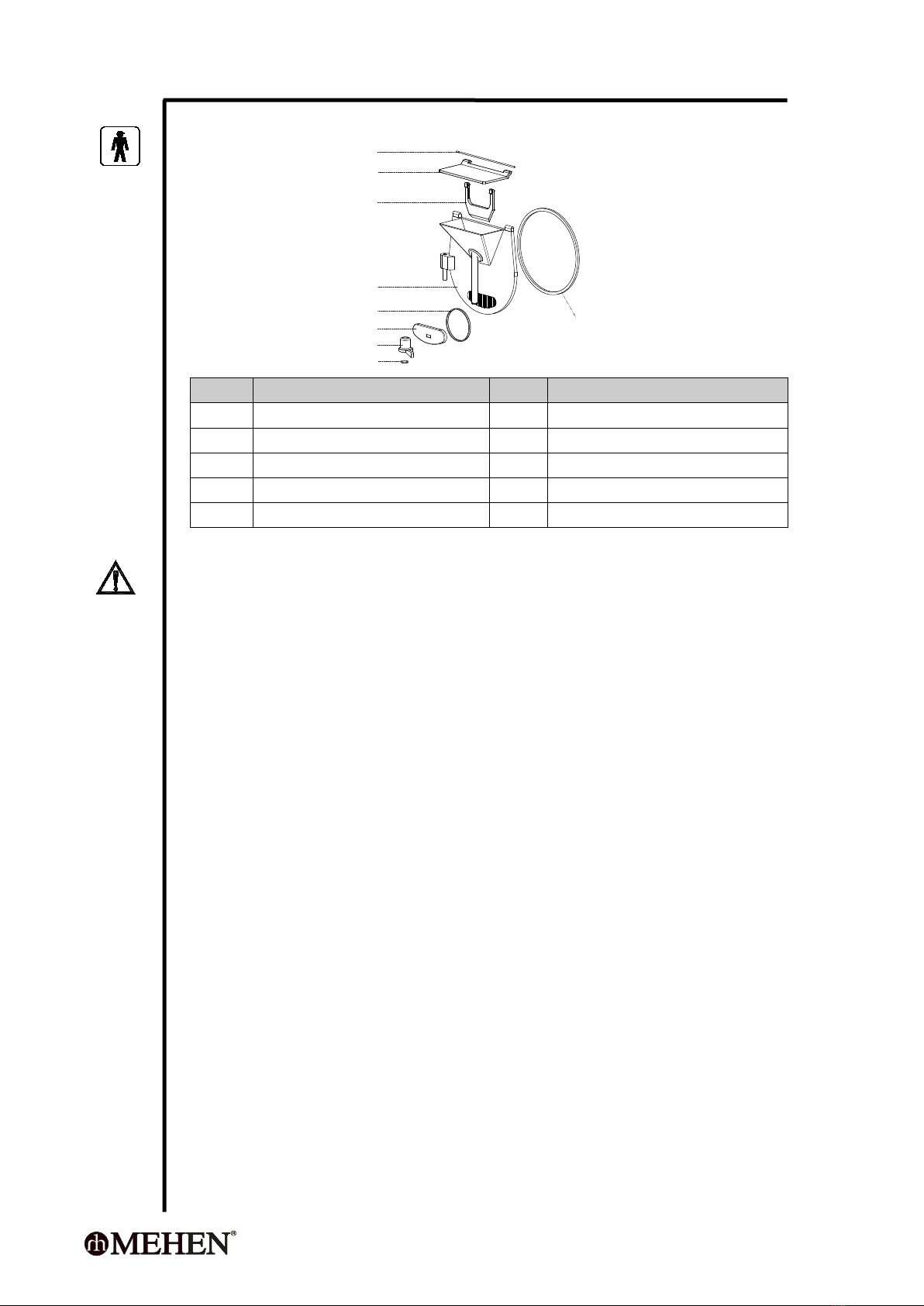
4.4 Cylinder Door Diagram
47101
47102
47103
47104
47105
47106
47107
47108
47109
Pos.
Description
Pos.
Description
47101
Cover axis
47106
Outlet door
47102
Inlet cover
47107
Handle
47103
Inlet stopper
47108
Handle stop ring
47104
Cylinder door
47109
Cylinder seal ring
47105
Outlet door seal ring
WARNING
When the machine is running, never put your finger or tool into the cylinder,
otherwise may cause serious damage to body or machine.
CHAPTER 5 CONTROLS AND OPERATION
The Touch-Screen-Controller (TSC), dynamically display the working status of the
machine, the main parameters of the operation can be carried out, as well as
fault-diagnosis. Built-in processing program, all parameters of each program can
be regulated freely. Thus to realize a simple and easy way to deal with variety mix.
5.1 Some Specified Concepts
There are some concept to be specified to understand this chapter well.
HOME PAGE (STANDBY MODE)
The machine will enter STANDBY MODE automatically after it is power on if
without any problem. All components stop working. Under HOME PAGE, the
LCD Screen will automatically get into Sleep Mode after 45 minutes standby
without any operation, when you touch the screen, it will wake up again.
ERROR MODE
The machine stop all running and give alarm message if the controller detects
some error.
MIX TEMPERATURE
In this manual, it refers to the mix temperature inside of the cylinder.

- 15 -
5.2 Electrical Control Panel
1 2
1-Logo 2-Touch Screen
5.3 Main Specification of Controller
Range of temperature detected: -50~+150℃
Range of temperature adjustable: 0~110℃
Ambient temperature range: 0℃~+50℃
Relatively humidity: 20%~85% (without moisture condensation)
Detecting accuracy: ±0.1℃
Accuracy of controls: ±1℃
5.4 Daily Operation
It will enter home-page after power on if no problems.
Press Hardness to start a product making with hardness-control-mode;
Press Time to start a product making with timer-control mode;
Press Temperature to start a product making with temperature-control-mode;
Press Developer to start a product making with developer-control-mode;
Press Rinse to perform a Rinse for cleaning;
Press Take Out to run a product taking out operation;
Press Parameter to regulate the parameters.
5.5 Producing Programs
There are 4 programs for producing, you can use them according to your recipe or
habit accordingly.
5.5.1 Hardness Mode
Under this mode, the controller will:
Detects the product texture hardness, it will finish freezing and turn to
agitating only when the setting hardness achieved;

- 16 -
Detects the product temperature and change the agitating speed according
to setting.
During processing, the operator can:
Press or to increase or decrease the target hardness;
Press Take Out to finish the processing and turn to take out the product;
Press High speed or Low speed to switch the agitating speed;
Press STOP to stop the processing and turn to Standby mode.
TIPS
The controller will automatically record the new setting and repeat from next time.
5.5.2 Time Mode
Under this mode, the controller will:
Perform a freezing processing according to the Time setting, it will finish
the freezing and turn to agitating only when the setting time is over;
Detects and display the product temperature.
During processing, the operator can:
Press or to increase or decrease the time setting;
Press Take Out to finish the processing and turn to take out the product;
Press High speed or Low speed to switch the agitating speed;
Press STOP to stop the processing and turn to Standby mode.
TIPS
The controller will automatically record the new setting and repeat from next time.
5.5.3 Temperature Mode
Under this mode, the controller will:
Perform a freezing processing according to the Temperature setting, it will
stop freezing and turn to agitating when the setting temperature is
achieved;
The compressor will restart if the product temperature increase 2 °C;
Detects and display the product temperature.
During processing, the operator can:
Press or to decrease or increase the temperature setting;
Press Take Out to finish the processing and turn to take out the product;
Press High speed or Low speed to switch the agitating speed;
Press STOP to stop the processing and turn to Standby mode.

- 17 -
TIPS
The controller will automatically record the new setting and repeat for next times.
Only Temperature-Mode has temperature holding function.
5.5.4 Developer Mode
The developer mode offers a flexible options for the chef to produce
different products;
The freezing will finish if the Setting Temperature is achieved;
The agitating will continuous until the operator manually press Take out or
STOP;
The entire temperature range is divided into 4 segments ( Fig 1.);
In each temperature range:
The operator can program the compressor: Continuous or Intermittent
working;
The operator can program the agitating motor: Low Speed,
Intermittent Low Speed, High Speed or Intermittent High Speed.
S1 S2 S3 S4
Fig 1
During processing, the operator can:
Press or to decrease or increase the temperature setting;
Press Take out to finish the processing and turn to take out the product;
Press STOP to stop the processing and turn to Standby mode.
TIPS
The controller will automatically record the new Target Temperature Setting and
repeat from next time.
We suggest you use this program only if you are experienced.
5.6 Program Setting
5.6.1 How to Set Program?
On Home-page, press Parameter will enter program setting mode;
Press the volume frame to regulate.
The new setting will be saved automatically.
time
temperature
Temperature 1
Temperature 2
Temperature 3
Target temperature

- 18 -
5.6.2 Programs Setting
Program
Parameters
Range
Unit
Factory
Volume
Explanation
Hardness
Target
hardness
1~12
==
8
Higher volume results in harder product.
Default
speed
Low/High
==
Low
Low: Low-speed agitation.
High: High-speed agitation.
Overrun
On/Off
==
On
The machine will automatically switch to
high-speed when the product temperature
is in the range of 1 °C ~ -3 °C.
Time
Time setting
2~35
minutes
10
Freezing time.
Default
speed
Low/High
==
Low
Low: Low-speed agitation.
High: High-speed agitation.
Temperature
Target
temperature
-15 ~ 2
°C
-8
Target temperature.
Default
speed
Low/High
==
Low
Low: Low-speed agitation.
High: High-speed agitation.

- 19 -
Developer
Target
temperature
-15 ~ 2
°C
-8
Target temperature.
Temperature1
-15 ~ 80
°C
2.0
Minimum temperature of S1 (refer to Fig 1)
Temperature2
-15 ~ 80
°C
-1.0
Minimum temperature of S2 (refer to Fig 1)
Temperature3
-15 ~ 80
°C
-5.0
Minimum temperature of S3 (refer to Fig 1)
Motor speed 1
Low speed
Intermittent low
High speed
Intermittent high
Low speed
Agitation speed in temperature range S1
(refer to Fig 1)
Compressor 1
Continuous
Intermittent
Continuous
Compressor mode in temperature range S1
(refer to Fig 1)
Motor speed 2
Low speed
Intermittent low
High speed
Intermittent high
High
speed
Agitation speed in temperature range S2
(refer to Fig 1)
Compressor 2
Continuous
Intermittent
Continuous
Compressor mode in temperature range S2
(refer to Fig 1)
Motor speed 3
Low speed
Intermittent low
High speed
Intermittent high
Low speed
Agitation speed in temperature range S3
(refer to Fig 1)
Compressor 3
Continuous
Intermittent
Continuous
Compressor mode in temperature range S3
(refer to Fig 1)
Motor speed 4
Low speed
Intermittent low
High speed
Intermittent high
Low speed
Agitation speed in temperature range S4
(refer to Fig 1)
Compressor 4
Continuous
Intermittent
Continuous
Compressor mode in temperature range S4
(refer to Fig 1)
5.7 Language
This controller offers a quick language setting.
On Home-page, press Parameter and enter Hardness-setting;
Then press Language to enter Language-setting;
Press the Language you want.

- 20 -
5.8 User Parameters Setting
5.8.1 How to Set User Parameters?
On Home-page, press Parameter ;
Press PgDn 3 times, then enter parameters setting.
Press the volume frame to change it;
The controller will save it automatically after each changing.
5.8.2 User Parameter List
Parameters
Range
Unit
Factory
Volume
Explanation
Compressor max.
working time
15 ~ 40
minutes
30
This is a safety device, the compressor will
stop working if exceeds this volume.
Take out freeze time
3 ~ 60
seconds
8
When taking out the product, press the
button Take out freeze will start the
compressor for few seconds according to
this setting. This is helpful for big capacity
machine.
Rinse time
3 ~ 240
seconds
30
When cleaning the cylinder, the agitation
motor will run a period of time according
to this setting.
Take out time
5 ~ 240
seconds
120
This is a timer, the agitation motor will
stop when the time is over.
Motor on time
5 ~ 180
seconds
60
Under Developer mode, the motor can
work on and off according to this setting.
Motor off time
5 ~ 120
seconds
10
Under Developer mode, the motor can
work on and off according to this setting.
Compressor on time
3 ~ 180
seconds
30
Under Developer mode, the compressor
can work on and off according to this
setting.
Compressor off time
3 ~ 180
seconds
60
Under Developer mode, the compressor
can work on and off according to this
setting.
This manual suits for next models
3
Table of contents


