Page 7 of 22 85-03-01096
PLANNING FOR VENT LOCATION
TV Installation Above Fireplace
An advantage of installing a Cool Wall Vent Kit with your fireplace is being able to install a television above the fireplace.
Using a Cool Wall Kit can make it possible to install a television above the fireplace. These instructions show Mendota’s
recommendations of installing a television above the fireplace when using a Cool Wall Kit.
When planning to install a television or other heat sensitive product above your fireplace, there are some points to consider.
Many television manufacturers specify in their installation instructions that the television must not be installed near or above
a heat source. The decision to install a television near or above a Mendota fireplace rests solely on the consumer. It is the
consumers responsibility to satisfy television specifications and insure the television will not exceed maximum operation
temperatures. Mendota Hearth will not be held liable for any adverse effects on a television or other products located near
to a Mendota Hearth fireplace.
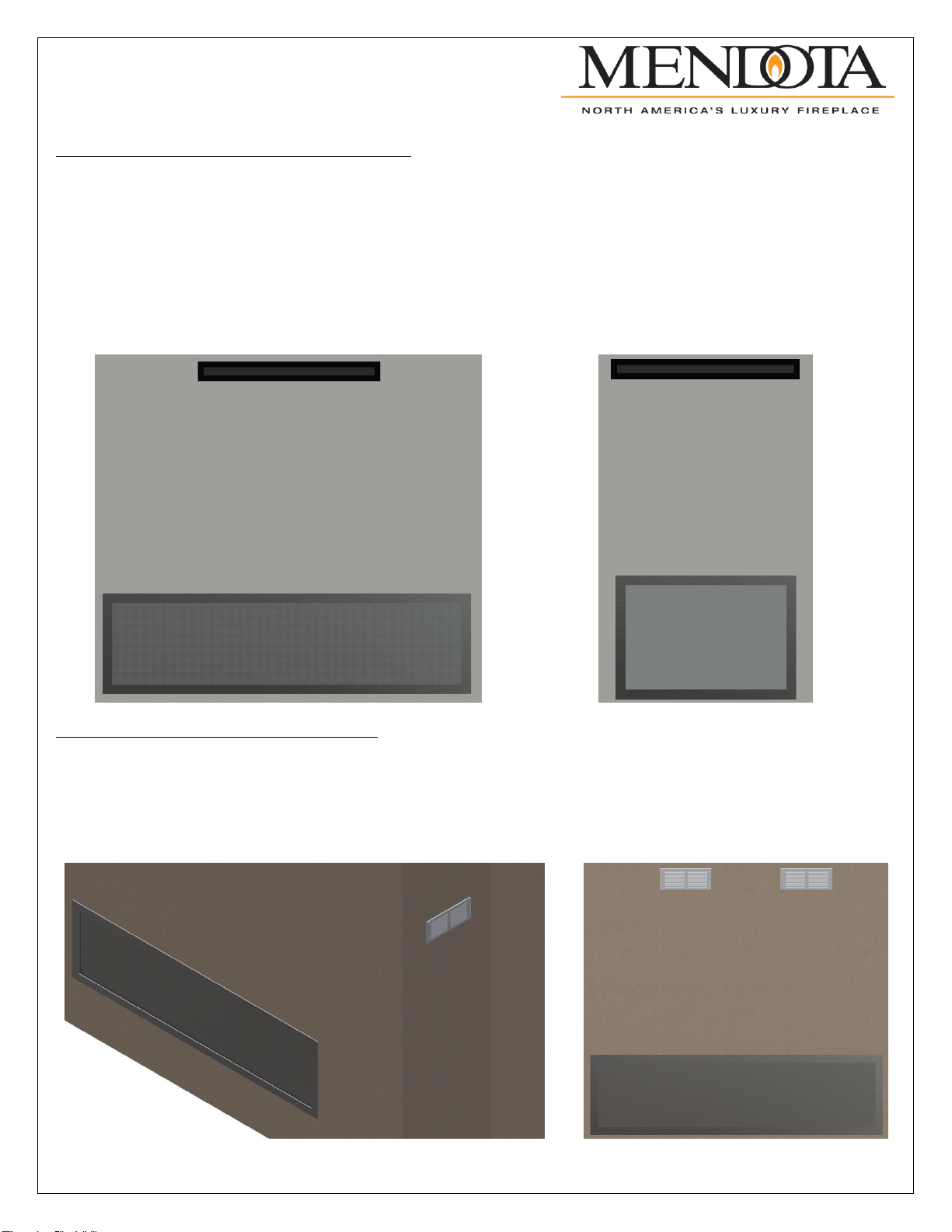
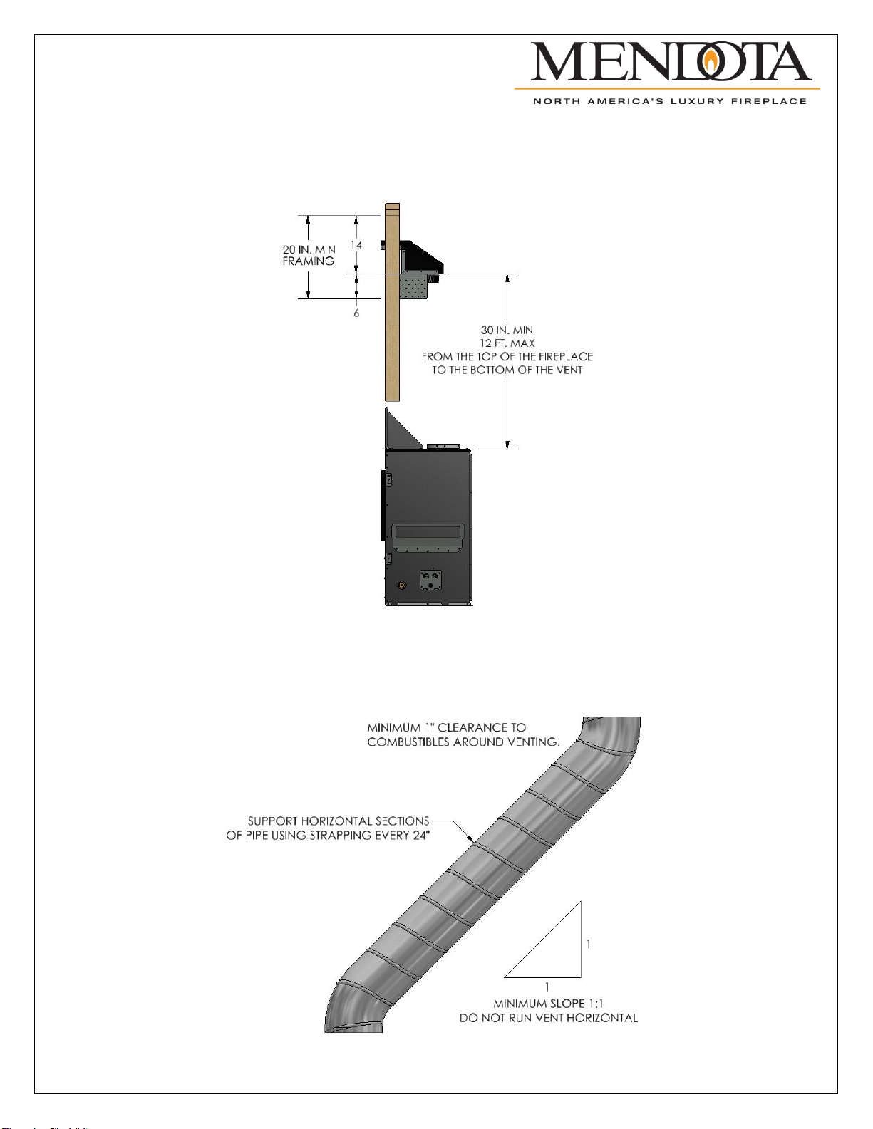
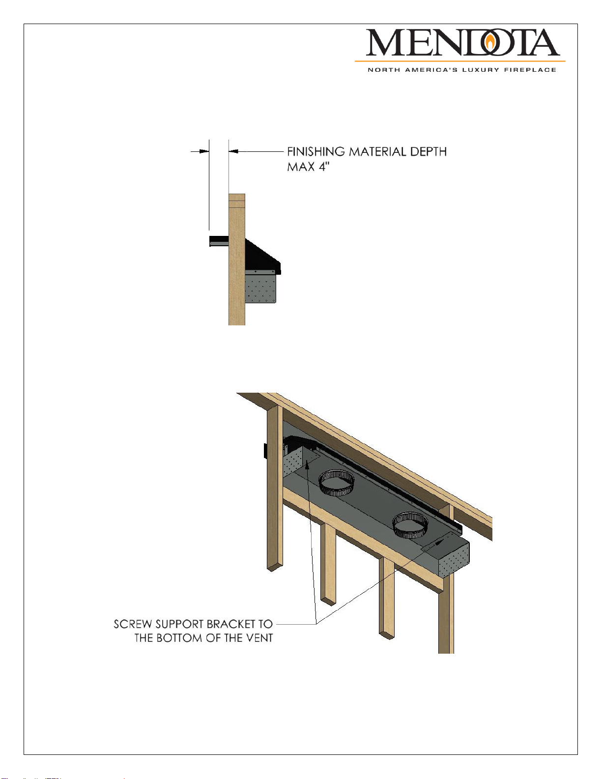
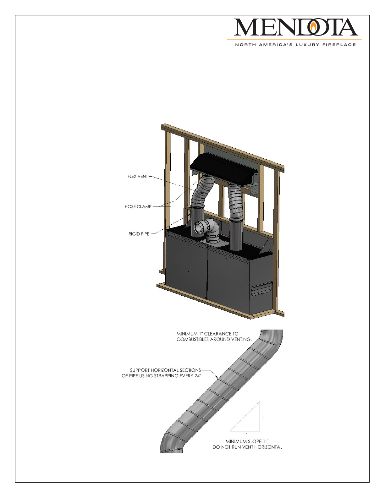
The drawing below shows a recommendation that may be used as a guide for those consumers that decide to locate a
television above a Mendota Hearth fireplace. The recommendation has been found to reduce the heat impact to a television
when installed above a Mendota Hearth fireplace.
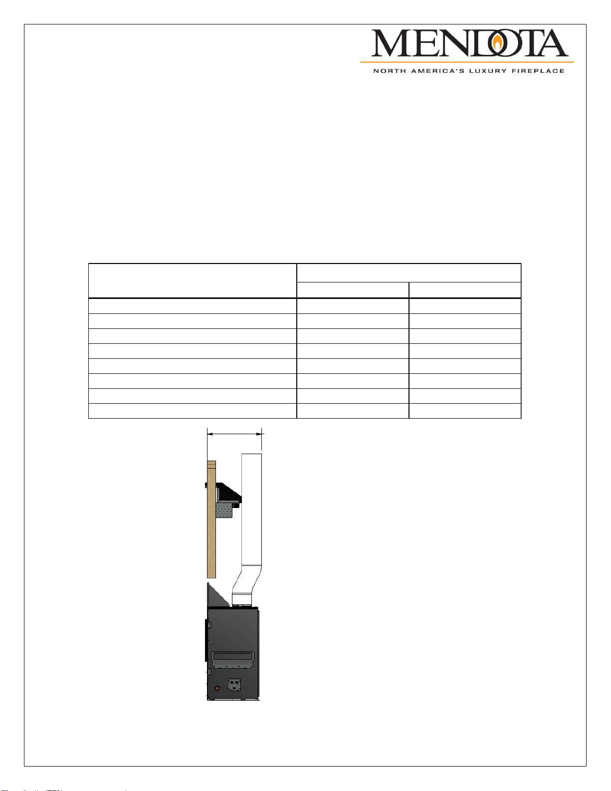
Recommendation for Installing a Television Using a Cool Wall Vent Kit.
WARNING: The convection fans on the fireplace must be turned off to insure the heat from the fireplace is redirected
through the Cool Wall Vent Kit. Turning the convection fans on will force heated air out the front of the fireplace, heating the
surrounding area.
-On fireplaces with a millivolt system: DXV35 Timberfire, DXV42, DXV60, M50 the convection fans must be
disconnected from power to insure they cannot be turned on.
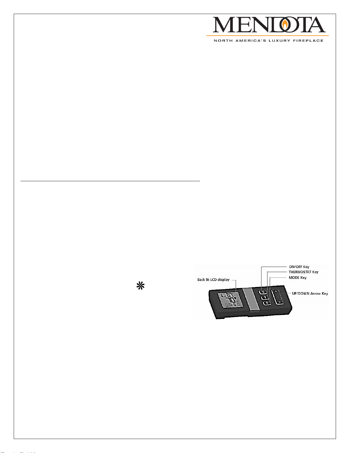
-On fireplaces with electronic ignition system that come with a PF2 remote the convection fans function must be
programed out of the remote. This will ensure that the convection fans cannot be turned on. Follow the directions
below to remove the convection fans function from the remote.
1. Remove a battery from the remote.
2. Hold down both the ON/OFF key and MODE key
and reinstall the battery.
3. Continue to hold the ON/OFF key. Release the
MODE key. Press the MODE key once to
highlight the convection fan function.
4. While still holding the ON/OFF key press the
DOWN ARROW key. The display will change
from “Set” to “Clr” to indicate that the convection
fan function has been disabled.
5. Release the ON/OFF key.