MetalMaster Chassis system 3.0 User manual

Metal Master chassis system 3.0
Instruction Manual
This is the manual for the Saber-chassis only.
It shows how to install the electronics and put together all chassis parts. This manual does not
show how to convert a Graflex Flashgun or setup a soundboard.
This manual contains the instructions for Metal Master chassis version
3.0
Metal Master ightsaber chassis is only recommended for experienced model builders
Manual Version 02.08.2022
1

Contents
1. Foreword 3
2. Tools 4
3. Additional parts overview 4
4. 3D print parts overview 6
Emitter Section 7
Plasma Gate Section (Part 01) 8
Crystal Chamber Section (Part 02, Part 03 Part 04) 9
Main Section (Part 05, Part 06, Part 07) 10
Main Section (USB) 11
Speaker Section (Part 08) 12
5. C ecking t e printed parts 13
6. Preparing t e surface 15
7. Installation 18
7.1 Electronic wire 18
7.2 Speaker Chamber 19
7.3 Battery contact installation 23
7.4 Battery cover Part07 26
7.5 Charge PCB 27
7.6 Accent ED/Pixel 31
7.7 Oled display installation 34
7.8 Fins installation (3D printed or laser cut) 36
7.9 Crystal chamber Part02 38
7.10 Installing t e Electronic parts 39
7.11 Plasma Gate 2.0 43
7.12 Spinning Plasma Gate (Part 01 SPG) 44
7.13 Blade older – Emitter 53
7.14 Installing the top cover Part 06 58
7.15 Installing the Battery 59
2

1. Foreword
T ank you for c oosing my Graflex Lig tsaber C assis for your own Graflex based Lig tsaber
project.
The mb-sabers Graflex chassis design has been continuously developed and improved for over 3
years. MB-sabers focused on this one chassis design to create the best possible chassis for Graflex
based ightsaber.
A lot of experience and passion has gone into this design. And of course mb-sabers will continue to
work on improving this chassis and adapting it to customer needs in the future.
The Metal Master chassis design allows individual parts to be simply exchanged for the old version
after further development. This often allows a complete chassis to be updated without having to
re-buy all parts.
For creative design
The metal Master chassis gives a lot room for individual custom designs.
Use the basic chassis parts and add self designed parts and elements to it. Especially the crystal
chamber and the plasma gate can easily be modified.
For experienced obbyists
Editing and assembling the individual parts is not easy. 3D printed parts are not that accurate as
CNC machined parts. Adjustments always have to be made. A proper workspace and professional
tools are absolutely necessary. I only recommend building one of my chassis for experienced
hobbyists.
Responsibility
3D printed metal is conductive. The installation of all electronic parts must be done with care! MB-
Sabers cannot be held responsible for improper use or assembly of the Metal Master Saber
Chassis.
Print materials
The Metal Master chassis is specially developed for metal 3D printing. Most parts are available as
3D prints. These parts are designed for precious metal materials. These materials have the best
accuracy and usability. They can be drilled, cut and tapped very easy.
However, most parts are also available in steel or nylon plastic.
3

2. Tools
For assembling the printed chassis parts and installing the electronic parts you need different
tools...
•sandpaper (240 grain and 600 grain)
•drill heads 1mm, 2mm, 3mm, 4mm
•small slot screwdriver
•double-sided adhesive tape (thin and foam)
•scalpel / small cutter
•tap M1.2 and M1.4
•glue (Pattex repair EXTREME and Epoxy)
•octite 648
•files with diamond grid (small and medium)
•soldering-iron and solder
•tweezers
•liquid rubber
•insulating tape
•shrink tubing
•belt sanders small (for example Proxxon)
•power tool (Dremel or Proxxon)
3. Additional parts
Basic C assis parts
•3x M2 threaded steel rods https://www.mb-sabers.com/shop
•1x M1.2 brass rod https://www.mb-sabers.com/shop
•2x 40mm steel rods (1mm diameter) https://www.mb-sabers.com/shop
•4x 95mm steel rods (1mm diameter) https://www.mb-sabers.com/shop
•2x brass tubes 40mm x 4mm diameter https://www.mb-sabers.com/shop
•3x M1.2 countersunk screws https://www.mb-sabers.com/shop
•6x M2 nuts DIN934 https://www.mb-sabers.com/shop
•4x M1.2 nut https://www.mb-sabers.com/shop
•power switch (TS01CQE 3A 120V)DigiKey
•micro USB-B or USB-C port (female) https://www.mb-sabers.com/shop
•1x AAA battery spring contacts https://www.mb-sabers.com/shop
•1x AAA battery contacts https://www.mb-sabers.com/shop
•3x M2 washer
•speaker cover ring https://www.mb-sabers.com/shop
•speaker chamber accent ED spacer https://www.mb-sabers.com/shop
•Emitter blade holder https://www.mb-sabers.com/shop
4

Plasma Gate Parts
•3x screws 4-40 UNC 3/4” https://www.mb-sabers.com/shop
•3x M2 nuts https://www.mb-sabers.com/shop
•1x poly carbonate tube (10mm diameter) https://www.mb-sabers.com/shop
•3x steel tubes (3mm diameter) https://www.mb-sabers.com/shop
•3mm ultra bright ED or pixel ED https://www.mb-sabers.com/shop
Electronic parts
•18650 3.7V i-Ion Battery (protected only!)https://thesaberarmory.com/
Keeppower 3,7V 18650 Lit ium-Ion 3500 mA
•1x 28mm speaker (max 12mm high) https://thesaberarmory.com/
•0.02 mm² (AWG 34) wire
•0.05 mm² (AWG 30) wire
•0.09 mm² (AWG 28) PTFE wire
•0.14 mm² (AWG 26) PTFE wire
•0.21 mm² (AWG 24) PTFE wire
•0.32 mm² (AWG 22) PTFE wire
•3mm accent EDs
•SMD EDs 0805
•single pixel ED
•Soundboard https://thesaberarmory.com/
•USB charging PCB https://www.mb-sabers.com/shop
•Oled display 0,91” (128 x 32)
•electric motor with gear box 1:136 (6mm) https://www.mb-sabers.com/shop
•NeoPixel connector (blade and hilt) https://thesaberarmory.com/
•High brightness ED https://thesaberarmory.com/
•Blade parts https://thesaberarmory.com/
https://www.thecustomsabershop.com/
GRAFLEX parts
•GRAF EX flash gun https://thesaberarmory.com/
https://graflexshop.com/
http://romanprops.com/
•GRAF EX add on parts https://www.thecustomsabershop.com/
https://thesaberarmory.com/
Blade older https://www.mb-sabers.com/shop
5

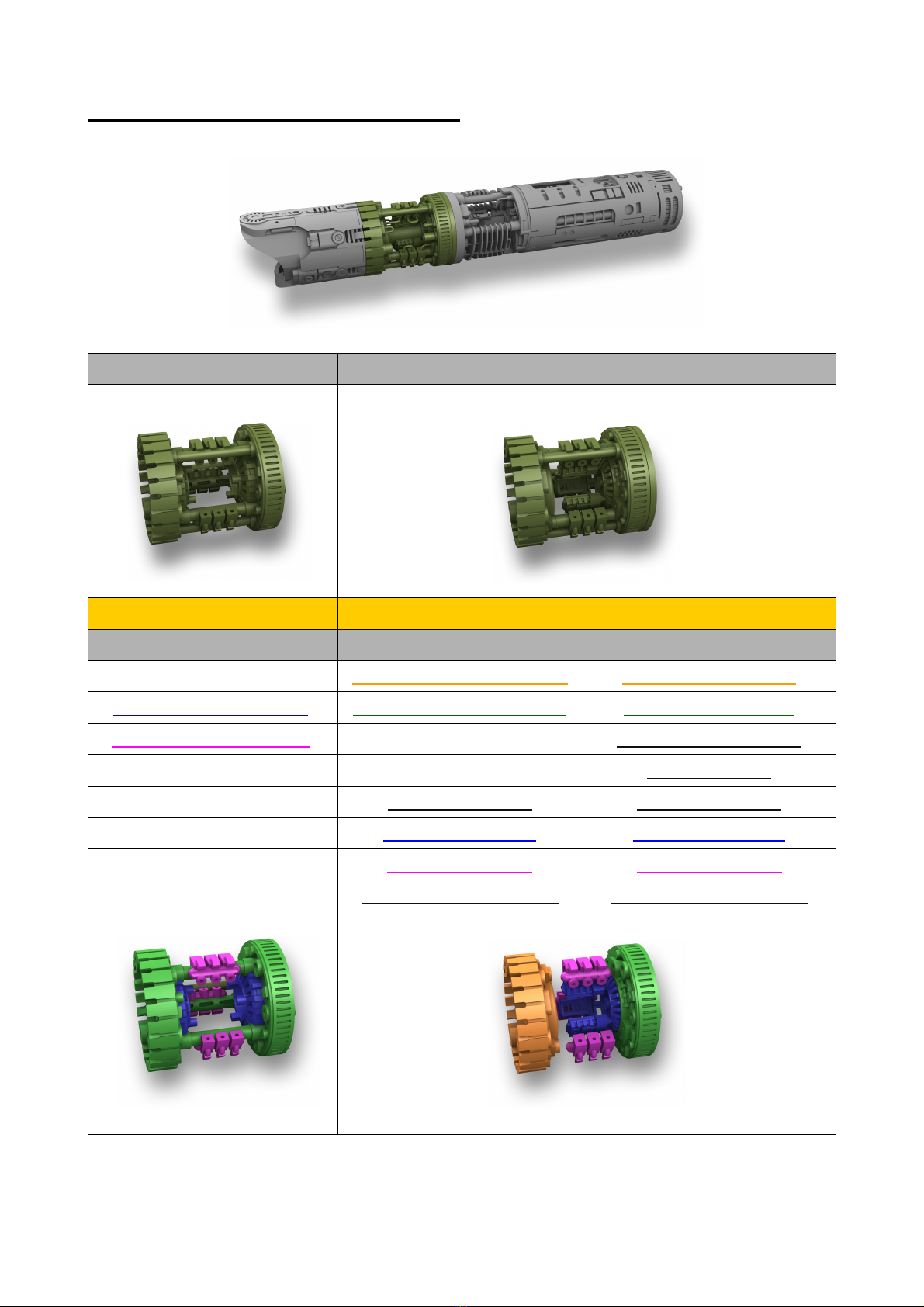
4. 3D print parts overview
Part Variations
Some parts have variations!
Depending on technical aspects like:
Blade style: NeoPixel or High Brightness ED
Plasma Gate: Standard or spinning
Oled display: YES or NO
USB: USB-B or USB-C
Or design aspects:
Crystal C amber: number of Fins
Main Section: number of accent ED on Part06
Print Materials
3D printed precious Metal:
The metal parts are designed for precious metal material printing (Silver, Brass, Bronze).
These materials have the best accuracy and usability. They can be drilled, cut and tapped very easy.
However, most metal parts are also available in steel or nylon plastic.
3D printed Steel:
Steel material prints are not recommended for inexperienced obbyist. But it is absolutely
possible to work with printed steel parts. It takes some time to prepare the parts to make them fit.
The standard SW steel material is brittle and cannot be drilled, cut or tapped! All steel material
prints have an accuracy of +/- 5%!
Anyway, the lower cost of steel prints are of course a good way to safe money.
6

Emitter Section
Variation A (short) t in back plate
for Neo Pixel
Variation B (long) t ick back plate
for ig brig tness LED
Parts Parts
Emitter glass-eye adapter Emitter glass-eye adapter
Emitter add-on A s ort Emitter add-on A long
Emitter add-on B Emitter add-on B
Emitter add-on C s ort Emitter add-on C long
Emitter add-on D s ort Emitter add-on D long
Emitter add-on E Emitter add-on E
Emitter 2.0 NeoPixel Connector older
7
Plasma Gate Section (Part 01)
Standard Plasma Gate Spinning Plasma Gate (SPG)
precious metal or steel precious metal steel
parts parts parts
Part 01 Plasma Gate 2.0 A Part 01 SPG front cast metal Part 01 SPG front steel
Part 01 plasma gate 2.0 B Part 01 SPG back cast metal Part 01 SPG back steel
Part 01 Plasma Gate 2.0 C Part 01 SPG tube older
Part 01 SPG ring
Part 01 SPG spacer Part 01 SPG spacer
Part 01 SPG magnet Part 01 SPG magnet
Part 01 SPG details Part 01 SPG details
Part 01 SPG motor older Part 01 SPG motor older
8

Crystal Chamber Section (Part 02, Part 03 Part 04)
Crystal Chamber with
5 fins
Crystal Chamber with
6 fins
Parts Parts
Part 02 A Part 02 A
Part 02 B Part 02 B
Part 02 C (crystal older) Part 02 C (crystal older)
Part 02 D (led older) Part 02 D (led older)
Part 03 Part 03
Part 04 (5 fins) Part 04 (6 fins)
Pipes Add On Pipes Add On
9

Main Section (Part 05, Part 06, Part 07)
V1 V2 Oled
Parts Parts Parts
Metal Master 3.0 part 05 Metal Master 3.0 part 05 Metal Master 3.0 part 05
Metal Master 2.0/3.0 Crystal
older
Metal Master 2.0/3.0 Crystal
older
Metal Master 2.0/3.0 Crystal
older
Metal Master 3.0 part05 slider Metal Master 3.0 part05 slider Metal Master 3.0 part05 slider
Metal Master 3.0 plate and
spacer
Metal Master 3.0 plate and
spacer
Metal Master 3.0 plate and
spacer
Metal Master 2.0/3.0
Insulation
Metal Master 2.0/3.0
Insulation
Metal Master 2.0/3.0
Insulation
Metal Master 07 Metal Master 07 Metal Master 07
Metal Master Battery cover Metal Master Battery cover Metal Master Battery cover
Metal Master 3.0 part06 V1 Metal Master 3.0 part06 V2 Metal Master 3.0 part06 Oled
Metal Master six-pack smd
LED Holder
Metal Master double smd LED
older
Metal Master LED Holder Oled
Metal Master Oled cover SET
10


5. C eck t e metal printed parts (especially standard steel)
After the printed parts arrive, they must first be inspected.
Most materials do not pose a major problem. However, parts printed from standard steel materials
may have imperfections. Nylon or precious metal parts s ouldn't cause any problems.
C eck all parts for:
- closed / blocked oles (try to push rods through each hole)
If there is a blocked hole make a picture (for Shapeways) before you do anything else.
If it is not possible to resolve this
issue by drilling or other
techniques please contact
Shapeways and reclaim the part.
They will reprint the part for you.
Use t is text:
I know the printing process. I
know it is possible to get a
perfect print result with this
model.
It looks like the print was not
checked and cleaned properly
after the first step before the part goes through the infusion process.
- bent geometry
If the object does not fit because of bent geometry try to reshape it. Steel material is brittle. So
you have to be careful.
First take pictures of t e
non-fitting part (for
S apeways). Then try to
reshape it.
In most cases it is
possible to make it fit
again. If it is not possible
then please contact
Shapeways and reclaim
this part. Send them the
picture of the issue and
ask for a reprint. They will
reprint this part!
13
- damaged surface caused by removing sprue marks.
During the printing process sprues are added to the geometry. These sprues will be removed after
the printing process. Sometimes Shapeways damages the part. Please contact Shapeways and
reclaim the bad print. Send them the picture of the issue. They will reprint this part!
Use t is text:
I know the production process. These damages are caused by removing sprue marks careless.
Please reprint this part.
14

6. Preparing t e surface
3D printed metal parts are never perfect! They all need post processing to make them fit and look
good. Depending on the material, the parts require more or less work.
Precious metals require the least amount of work. Standard steel needs the most amount of work.
Tools
- power tool and grinding heads
- diamond files (small)
- sandpaper (240 grit, 600 grit)
- belt sander (80 grit and 180 grit)
Precious Metal parts (Brass, Bronze, Silver) in general:
Precious metal material can be ordered as polished or raw.
I recommend to order t e raw version. It is a lot cheaper. It is easy to sand or polish by yourself.
Also polished precious metal print lose detail and edges are rounded.
For preparing precious metal parts, belt sander, sandpaper and small files are needed.
15

Steel parts in general:
Steel parts do not fit wit out sanding.
Each part has to be sanded. Take your time. For steel parts use your Dremel or Proxxon power tool
with a grinding head.
For the finish use a belt sander (80 grit and 180 grit).
There are several areas which have to be sanded to make sure all parts fit together.
For the holes use small (2mm) grinding heads with your Dremel and small round hand files.
Standard Steel material cannot be drilled. Always use grinding heads, sand-paper or a diamond
file.
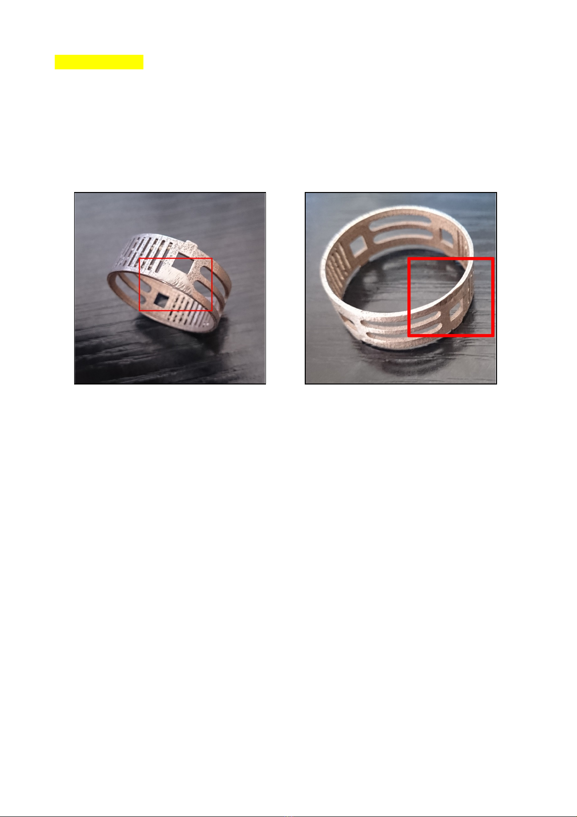
Steel parts w ic need more attention:
Battery cover Metal Master 07 (steel)
It is also necessary to sand down well the
rough surface inside the battery section from
part 07 (battery cover).
The battery has to have enough space to lay
in the battery cover loosely. T e battery cover
must fit easily! T is is very important.
16

Soundboard cover Metal Master 06 (steel)
Some areas of the soundboard cover Metal
Master 06 need special attention.
The area around the “light holes” inside the
cover need to be sanded carefully to make
sure the ED holder fits. This area has to be
nice and smooth.
Other areas at the holders must be sanded to
make the cover fit on the main part Metal
Master 05.
C eck t e fitting first. T en decide w ere and
ow muc material as to be removed. Eac
steel print is different.
Plasma Gate Part 01 and Part 02
All areas marked in red have
to be sanded to make the
steel parts fit.
Take your time to make everyt ing fit toget er...
17

7. Installation
! Safety first !
Please remember t at metal materials are conductive! You ave to make sure t at t e battery
contacts are well insulated as well as all ot er electronic parts.
Do not mix up t e electronic poles. Install t e contacts like s own on t e pictures.
Electronic wire
Use PTFE wire. PTFE as t e smallest profile.
function AWG mm²
speaker 26 0.14
single Pixel 30 0.05
Pixel data 30 0.05
+ battery to + Soundboard 24 0.21
- battery to - Soundboard 22 0.32
+ battery to + pixel blade 22 0.32
- pixel blade to Soundboard 22 0.32
motor 28 0.09
Plasma Gate Pixel PCB 26 0.14
USB port D+/D- to Soundboard 34 0.02
USB port <> charge PCB 28 0.09
Battery <> charge PCB 28 0.09
AUX/ACT switch 34 0.02
Accent smd EDs 34 0.02
18

Speaker c amber
M2 t readed rods preparation
Install one M2 nut on each M2 threaded rod end (2x).
You need two 135mm long M2 rods.
T e t ird one is s orter and will be installed later!
Use Loctite 648 to glue them in position. et it dry over night.
T ese t ree rods ave to be installed before t e speaker c amber
is screwed on...
Speaker-C amber mounting ole tapping
Seven holes in the back of Part 05 need 1.2M threads.
Use a M1.2 tap set of three.
Drill the holes to 1mm and cut the threads.
Use t e tap guide! Link : Part 05 tap guide
If you have problems to get a M1.2 tap like this: info mb-sabers.com
Polis ing t e back of part 05
Polish the back of Part 05 to a mirror finish. This effects the brightness of the speaker chamber
accent ED.
19

Preparing t e speaker c amber LED-SPACER
The spacer guides the speaker chamber's accent ED light.
Remove the blue foil from the LED spacer.
This part does not have to be glued. Just place it between part 05 and the speaker chamber.
Attach a thin self-adhesive mirror film to the side facing the chamber. Cut out a 5mm x 5mm area
in the center.
Cut two notches into the ED spacer like shown on the picture. Use the rod guides on the chamber
to find the correct position! Make sure 1mm rods fit and slide easy t roug t e guides, notc es
and oles!
Preparing t e speaker c amber frame rods
The speaker chamber is framed by four
1.2mm rods.
Use four 1.2mm rods and cut M1.2
threads to each end.
(Or use 1.2mm pre threaded rods LINK)
1. Cut four 1.2mm rods to 2.5cm length.
2. Tap a thread on one end of each rod.
3. Screw them onto Part05, add the
speaker chamber and speaker ring. Adjust
the length of both ends of each rod.
4. Tap the other end of each rod.
20
Table of contents


