Monodraught Cool-phase Nova Installation and operation manual

Typical Operating & Maintenance
Manual
Project Name –Cool-phase® Nova Ceiling Mounted Low Energy
Cooling & Ventilation System

Project name / Order No SC
Halifax House, High Wycombe, Buckinghamshire, HP12 3SE 2
Contents:
1. Company details
2. Maintenance Programme
3. Equipment schedule
4. Manufacturers Product Details
5. Operating Instructions
6. Maintenance Instructions
7. Wiring Requirements
8. Control Strategy
9. Decommissioning / Dismantling Requirements (including COSHH Data Sheet)
10. Records of Commissioning
11. Monodraught Working Drawing
12. COSHH Data Sheet
13. COOL-PHASE® BACnet module Data Sheet
1. Company Details:
Monodraught Ltd.
Halifax House
Cressex Business Park
High Wycombe
HP12 3SE
Tel: 01494 897700
Fax: 01494 532465
E-Mail: [email protected]om
Website: www.monodraught.com
2. Equipment Installed:
1N° COOL-PHASE® Nova Low Energy, Ventilation, Cooling and Heat Harvesting System.
Serving: - ……………………………………….
3. Warranty of period:
The warranty shall apply for; 5 years for natural cooling products. The solar driven, mechanical and
electrical components of such Goods shall have a warranty period of 1 year. For full details of our
warranty please see our terms and conditions available on our website.
4. Maintenance Programme:
To ensure that the warranty on the equipment supplied is maintained, and that the systems operate
to the optimum, it is important that the appropriate servicing is carried out. Monodraught
recommends that the systems are serviced on an annual basis. For full details of the programme refer
to maintenance section and for a Service quotation, please contact us at
serviceteam@monodraught.com

Project name / Order No SC
Halifax House, High Wycombe, Buckinghamshire, HP12 3SE 3
5. Manufacturers Product Details & Operation:
Please see below for the specification sheets.
SPECIFICATION
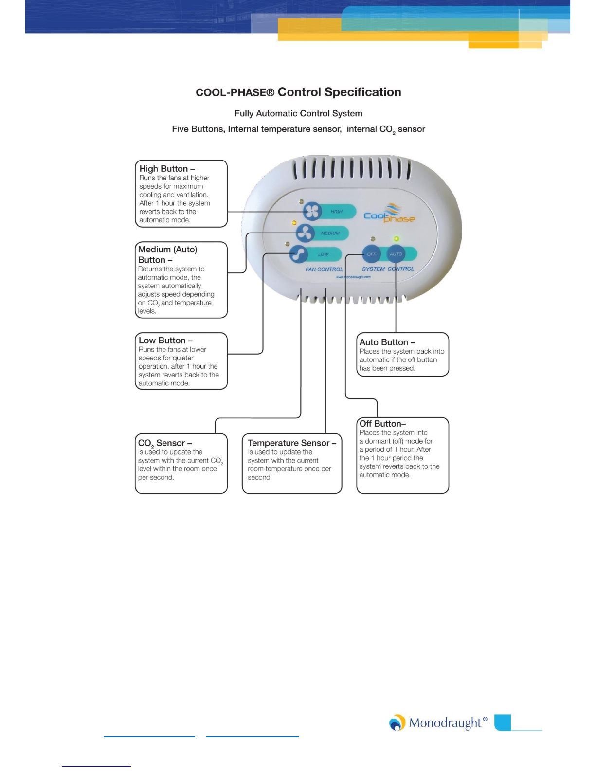
COOL-PHASE® low energy cooling and ventilation system
COOL-PHASE® is a low energy cooling and ventilation system that reduces the running costs of
buildings and creates a fresh and healthy indoor environment. The system uses a thermal energy
store comprising of a phase change material (PCM) in combination with intelligently controlled
mechanical ventilation to actively cool and ventilate the building. The COOL-PHASE system has been
developed for use in the commercial, education and healthcare environments.
The COOL-PHASE system can maintain temperatures within the comfort zone, while radically
reducing energy consumption by up to 90%, compared to a conventional Air Conditioning system.
The reduction in energy usage combined with low servicing and maintenance costs and a long life
result in a strong financial case over traditional cooling approaches. Since no compressors or
hazardous coolants are used, the system also has a number of environmental benefits, while the lack
of external units means the COOL-PHASE system can be used where outside space or planning
permission is an issue.
Features:
Ceiling mounted COOL-PHASE low energy cooling and ventilation system, supplied
complete with:
Air Handling Unit:
Air Handling Unit (AHU) comprising of a low energy, variable speed elliptical curved fan.
Intelligent control system with integrated data logger.
Rotational Air Director Drum.
Temperature sensors.
Thermal Batteries:
Thermal Battery modules including phase change panels.
Optional LED lighting to indicate battery charge.
Temperature Sensors.
Battery Options:
4 Thermal Battery Modules (6kWh).
6 Thermal Battery Modules (8kWh).
8 Thermal Battery Modules (10kWh).
Recirculation Module:

Project name / Order No SC
Halifax House, High Wycombe, Buckinghamshire, HP12 3SE 4
Recirculation module consisting of high grade G4 bag filter.
Temperature, Humidity and Differential Pressure Sensors.
Intake Damper for external ventilation.
Recirculation Damper for Recirc and mixed ventilation.
Ductwork, Fascias & Wall Controller
Pre insulated acoustic ductwork is provided to connect the COOL-PHASE system to outside
air, with a window, wall or roof louvre and exhaust grille (if supplied by Monodraught).
Fascias and air diffusers are provided when the COOL-PHASE system is suspended below the
ceiling.
For installation above a false ceiling plenum chambers, ceiling tiles and diffusers are supplied
to suit (if supplied by Monodraught).
COOL-PHASE wall mounted controller incorporating temperature, humidity and CO2sensors.

Project name / Order No SC
Halifax House, High Wycombe, Buckinghamshire, HP12 3SE 5
6. Operating Instructions:

Project name / Order No SC
Halifax House, High Wycombe, Buckinghamshire, HP12 3SE 6
Touchscreen LCD Wall Controller:

Project name / Order No SC
Halifax House, High Wycombe, Buckinghamshire, HP12 3SE 7
Wiring Diagram

Project name / Order No SC
Halifax House, High Wycombe, Buckinghamshire, HP12 3SE 8
7. Maintenance Instructions:
7.1. Maintenance Schedule:
After one year from installation a service agreement is required. If regular maintenance is not
carried out the warranty of the product will be invalidated. A typical maintenance schedule is shown
below. For any maintenance queries please contact: serviceteam@monodraught.com
Time interval
Carried out by
Checks
Procedure
3 months
User
Switch off unit, check
condition of air filter,
replace if required.
Clean Grilles internally
Filters available from
Monodraught
6 months
User
External inspection to
ensure the external wall
or window louvre is not
blocked with leaves or
debris.
Switch off COOL-PHASE
unit. Remove debris with
a brush and clean with
soapy water if required.
After 1 year, &
annually
thereafter
Monodraught
Monodraught will service
the system and ensure
system has latest
firmware. Replace filter.
Depending on service
contract arrangements,
Monodraught will make
contact to arrange
suitable time to access
the system.
7.2. Recirculation Air Intake Filter:
The Recirculation filter will be located within the Recirculation module at the point where the air
enters the building before being ducted to the COOL-PHASE unit –see project layout drawings for
individual locations. The filter is required to ensure both the quality of the ventilation air supplied to
the room and to protect the ducting and COOL-PHASE unit from the build up of dirt. If the filter is
dirty, a replacement should be fitted as it will inhibit the performance of the system. Changing filters
regularly will extend the life of the product. G4 grade filters are fitted as standard and replacements
can be purchased directly from Monodraught. Recirculation filter will need replacing at a minimum
of every 1 year, but will depend on the buildings location & the quality of external air. The COOL-
PHASE unit should be switched off prior to filter maintenance.
7.3. Thermal Battery Maintenance:
The Phase Change Material (PCM) is fully encapsulated to create a “Thermal Battery” and needs no
specific maintenance; it has a design life of 20 years and is guaranteed for 5 years subject to service
agreement.

Project name / Order No SC
Halifax House, High Wycombe, Buckinghamshire, HP12 3SE 9
7.4. Monodraught COOL-PHASE Service Points:
Run test program and review all functions.
The elliptical fan will be checked for correct operation.
Thermal Battery performance verification.
Firmware updated to latest revision.
Check all sensors operating within parameters, and re-calibrate if necessary.
COOL-PHASE System, Thermal Batteries and ductwork checked for cleanliness.
Filter change.
Data logs downloaded for optional performance case study.
Correct operation of actuators within the recirculation module.
Correct operation of Rotational Air Drum.
The COOL-PHASE system is considered a fixed piece of equipment and is therefore not subject to
PAT testing.

Project name / Order No SC
Halifax House, High Wycombe, Buckinghamshire, HP12 3SE 10
8. Wiring Requirements:
8.1. Wiring Diagram A –Wiring Details for 1N° COOL-PHASE Unit:

Project name / Order No SC
Halifax House, High Wycombe, Buckinghamshire, HP12 3SE 11
8.2. Wiring Diagram B –Wiring Details for 1N° COOL-PHASE SLAVE Unit:

Project name / Order No SC
Halifax House, High Wycombe, Buckinghamshire, HP12 3SE 12
8.3. Wiring Diagram C –Wiring Details for 1N° COOL-PHASE Nova system
inter-AHU configurations:

Project name / Order No SC
Halifax House, High Wycombe, Buckinghamshire, HP12 3SE 13
9. COOL-PHASE Control Strategy
The COOL-PHASE® system is a mechanical cooling and ventilation system, utilising a seasonally adjusted
control strategy with thefollowing inputs;
Time
Date
Internal Temperatures
ExternalTemperatures
Internal CO2 levels
The system comes supplied with a wall controller for local user inputs and eachunitcan be run in either
Slaveor Master mode.
9.1. Zonal Control Strategy:
The COOL-PHASE system can be run as a standalone system supplied with 1N° wall mounted control
system serving a single room or area.
Multiple COOL-PHASE systems can be run alongside each other independently with their own wall
mounted control system, or a maximum of four COOL-PHASE units can operate in a master / slave
arrangement with a single wall controller providing user inputs. This allows multiple COOL-PHASE
units to operate in a single room or zone of a building.
9.2. Inputs:
The system uses the following inputs. Details of user controls are contained in Section 4.
9.2.1. Fire Alarm Input (Optional):
When the fire alarm is activated the COOL-PHASE system will automatically close down until the
fire alarm is deactivated the COOL-PHASE system will then return to automatic mode.
9.2.2. User Overrides:
The user can increase or decrease the fan speed when the system is active by pressing the
‘HIGH’ or ‘LOW’ button on the wall controller. Similarly, the system can be turned off for one
hour by pressing the ‘OFF’ button.
9.2.3. CO2Input:
If the CO2Level in the zone exceeds 1000ppm concentration level the system will increase the
flow of external air into the room until the CO2level is reduced to 900ppm levels
8.2.4 Temperature Input:
In the cooling season the system will monitor internal temperatures to provide cooling when the
temperature exceeds 23°C. The amount of cooling is determined by the temperature difference,
and the system will continue to cool to maintain comfortable indoor environment.

Project name / Order No SC
Halifax House, High Wycombe, Buckinghamshire, HP12 3SE 14
In the heating season the system will monitor temperatures to ensure they remain above the
heating set point (See system config setting).
8.2.5 Input Priority:
9.3. Control Inlet Dampers:
There are three positions for the inlet volume control dampers:
1. External Air –Air is brought in from outside the building only. No recirculation occurs.
Name
Priority
1
Fire Alarm Input
Highest
Lowest
2
User Override
4
CO2 Sensor
5
Temperature Sensor

Project name / Order No SC
Halifax House, High Wycombe, Buckinghamshire, HP12 3SE 15
2. Recirculation –Air is re-circulated within the room or space only. No air is brought in from
outside.
3. Mixed Air –Re-circulated air is
mixed with outside air. The volume controller dampers control the proportion of re-
circulated air to external air.

Project name / Order No SC
Halifax House, High Wycombe, Buckinghamshire, HP12 3SE 16
9.4. Outlet Air Paths:
There are two positions for the outlet control dampers:
1. Direct Ventilation –Air is passed directly into the room. No air is passed through the PCM
heat exchanger.
2. PCM Heat Exchanger –Air is passed over the PCM Heat Exchanger to charge or discharge the
thermal energy store before entering the space.

Project name / Order No SC
Halifax House, High Wycombe, Buckinghamshire, HP12 3SE 17
9.5. Operating Modes:
9.5.1. PCM Re-Charge Mode:
During the warmer months of the year and when the room is unoccupied at night the system
will automatically pull in external air and pass it over the PCM heat exchanger to re-charge the
COOL-PHASE thermal batteries.
9.5.2. Summer Pre-Cooling Mode:
During summer, Cool-Phase brings in cool air to pre-cool the fabric of the building, increasing the
cooling effect for the following day.
8.5.3 Cooling Mode:
Should the temperature in the room exceed the seasonal pre-set level, the system will provide
cooling proportionally to meet the requirements of the space by varying the damper positions
and fan speed.
Cooling is provided through the effects of free cooling (when the temperature outside is cooler
than inside) and by intelligently using the energy stored in the PCM heat exchanger to cool the
space.
8.5.4. Ventilation Mode:
Should the CO2levels within the space rise above the seasonal pre-set level then the system will
provide ventilation proportionally to meet the requirements of the space, by opening the
external air damper and varying the fan speed until the desired CO2 levels are reached.
If cooling is required then the system will provide the required ventilation whilst maximising the
cooling effect. If it is cooler inside than outside then the system will mix the air to minimise the
amount of air taken from outside whilst meeting the ventilation requirements. If it is cooler
outside than inside then the system will provide air from outside only.
If cooling is not required then the system will prevent the temperature from falling below a pre-
set level. In winter the PCM heat exchanger can be used to temper the air before it enters the
room. The system can also mix internal air with external air before it enters the building to
prevent any cold draughts.
8.5.5. Heat Recovery Mode:
During the cold months of the year when either the room is unoccupied or the temperature
exceed preset levels the system will recirculate internal air over the PCM heat exchanger to
charge the thermal energy store and capture this waste / excess heat.

Project name / Order No SC
Halifax House, High Wycombe, Buckinghamshire, HP12 3SE 18
8.6. Summary Table:
9. Decommissioning / Dismantling Requirements:
9.1. PCM Modules and Air Handling Unit
The COOL-PHASE system can be dismantled with relative ease separating the various materials. The
expanded polypropylene (EPP), aluminium and steel used within the system are all suitable for
recycling. The insulated duct work is safe to be disposed of in general waste.
9.2. Electronics and Electrical Components
The electronic components used to control the COOL-PHASE system under the WEEE/EA0749YY
directive can be sent back to Monodraught for disposal and recycling.
Season
Spring
Summer
Autumn
Winter
Start Date
01-March
1-June
1-Sept
01-Dec
Finish Date
31- May
30 - August
30-Nov
Last day of Feb
Occupied
hours (Day
time)
Cooling provided
when room
temperature
reaches > 23°
Ventilation
provided when
internal CO2
levels reaches >
900 ppm
Cooling provided
when room
temperature
reaches > 22°
Ventilation
provided when
internal CO2
levels reaches >
800 ppm
Cooling provided
when room
temperature
reaches > 23°
Ventilation
provided when
internal CO2
levels reaches >
900 ppm
Cooling provided
when room
temperature
reaches > 24°
Ventilation
provided when
internal CO2
levels reaches >
1000 ppm
Un-occupied
hours
(Night Time)
PCM recharge
mode
Summer recharge
mode and pre-
cooling of the
space.
PCM recharge
mode
Heat recovery
mode, or winter
recharge mode.

Project name / Order No SC
Halifax House, High Wycombe, Buckinghamshire, HP12 3SE 19
9.3. Thermal Batteries
The thermal batteries can be removed from each end of the COOL-PHASE system. The internal
compound can be removed and disposed of (please see COSHH Sheets). The aluminium outer shell
can be recycled.
Records of Commissioning:
Monodraught’s commissioning report will be forwarded upon completion of the project.
Monodraught Working Drawings:
Please find attached copies of Monodraught drawing N°s (…………………………….)
Manual compiled by:
Date Compiled:
13/09/2017
Signed:

Project name / Order No SC
Halifax House, High Wycombe, Buckinghamshire, HP12 3SE 20
W: www.monodraught.com E: info@monodraught.com T: 01494897700
Table of contents
Popular Ventilation manuals by other brands

Brink
Brink Renovent Sky 200 installation instructions

Fantech
Fantech SHR6904 installation manual

EZ Breathe
EZ Breathe 400 installation guide

Greenheck
Greenheck IGX Installation, operation and maintenance manual

Delta
Delta GBR80MHLED Installation and operating instructions

Delta
Delta VFB050B3A1 instructions