Nambuk NRD-1000 User manual

Product Manual
Radial Drilling Machine
NRD - 1000
1 . Product manual must be read before use.
2 . Please read all instructions carefully prior to operate the machine.
3 . This machine is produced by Korea Certification Safety(KCS)
And Product Liability(PL)

Operating Manual
NRD-1000
2
Nambuk Co.,Ltd
Table of Contents
1
Introduction
3
2
Important Safeguards
4
2-1 Warning Sign
2-2 Warning Symbols
2-3 Warning Label
2-4 Attachment of Warning Label
2-5 Safety Precaution
3
Product Description
12
3-1 Specifications
3-2 Descriptions of each part of the machine
3-3 Accessories
4
Characteristics of Product
14
4-1 Spindle Box
4-2 Spindle
4-3 Spindle Manual Gear
4-4 Feed Gear
4-5 Speed Change Gear of Spindle
4-6 Feed Speed Change Gear
4-7 Base
4-8 Column & Sleeve
4-9 Arm
4-10 Electric Control Box
4-11 Arm Elevating Box
4-12 Tool Ejector Device
5
Transportation and Installation of Machine
16
5-1 Transportation and Unload Machine
5-2 Wiring
5-3 Installation of Machine
5-4 Balance of Product
5-5 Fueling

Operating Manual
NRD-1000
Nambuk Co.,Ltd
3
6
Operation of the Machine
20
6-1 Power Source Input of the Machine
6-2 Rotation Direction of Spindle
6-3 Feed of Spindle
6-4 Ascending and Descending of Arm
6-5 Column & Arm Clamp
6-6 Spindle box Clamp
6-7 Selection of Spindle Rotation
6-8 Conversion of Feed Speed
6-9 Automatic Feed of Spindle
6-10 Manual Feed of Spindle
6-11 Fine Feed of Spindle
6-12 Selection of the depth of Automatic Feed of Spindle
7
Adjustment of Machine
23
7-1 Adjustment of Column Clamp
7-2 Interval Adjustment between Arm and Column Sleeve &Adjustment of Clamp
7-3 Adjustment of Spindle Box Clamp
7-4 Slide surface interval & Horizontal leveling adjustment of spindle box and Arm
and Before&Behind Horizontal leveling
7-5 Adjustment of Safety Clutch for Spindle Feed
8
Electric Wiring
25
8-1 List and Usage of Electrical component
8-2 Electric Circuit Diagram
8-3 Switch Explanation of Electric Circuit Diagram
9
Parts List
32
10
Reference
50
10-1 Plate Name of Manufacturing No.
10-2 Protection Guard Manufacturing Diagram
11
Cutting Data
51
● Notice
We are truly grateful for purchasing our Radial Drilling Machine “NRD-1000”. NRD-1000
is easy to operate and was designed in accordance with KSB-4036 for safety
and raising productivity.
This manual will provide you information and safety use of NRD-1000
Please contact us for more information and details with the type of the machine and
serial number. If you need A/S man, we will visit immediately.

Operating Manual
NRD-1000
4
Nambuk Co.,Ltd
1. Introduction
Please read all instructions carefully prior to operate the NRD-1000
w This operating manual for the Radial M/C is for person who install, repair and run the machine.
w It explains basic details applicable all machine. Also, this manual is easy to understand
for beginners as well as consumers who use the machine for the first time.
w It describes the name and function of each part of the machine, how to operate and run
the machine, and finally inspections.
w Only when you perfectly know how to operate it and inspect it everyday, it is possible to
run the machine smoothly and safely
w Use this manual to understand the machine and to make the best use of it.
Precaution to be observed for safe handling of the machine
w This Radial machine should be operated only by persons who possess fundamental
mechanical and electrical knowledge and sufficient experience related to industrial
machinery.
☞-Mechanical trouble and accidents may occur when the machine is operated by persons
who don’t have sufficient knowledge and experience on the machine.
-Because there are many kinds of products according to users, each condition of
machining the products should be operated under responsibility of the users who have
thorough knowledge on the machine.
☞-Inappropriate conditioning of the machine and errors in operation may be causes of
accidents including mechanical trouble and personal injury.
-The machine has various kinds of safety devices, which users should know completely
for safety.
☞-Operating the machine when safety devices are removed or reorganized may be causes
of accidents including mechanical trouble and personal injury.
-Do not operate or repair the machine before you completely understand the manual.
Make sure that is impossible to operate beyond the manual.
☞-Make sure to read it carefully and observe these precautions.

Operating Manual
NRD-1000
Nambuk Co.,Ltd
5
◉Warning Labels are attached to the Radial Machine for safety.
the meanings of key words used in this manual to indicate the extent of danger to
persons or to the machine are defined below. These are based on the American
National Standards Institute(ANSI). Operate this machine only when you understand
the machine and the extent of danger sufficiently to prevent accidents.
2. Important Safeguards
2-1. Warning Signs
Warning signs of this manual and the machine are divided 4 levels as below
This sign indicates extremely fatal situation
that may cause serious personal injury or
even death.
This sign indicates dangerous situation that
may cause serious personal injury or even
death.
This sign indicates any situation that may
cause light or serious personal injury and
mechanical trouble.
Attention
This sign indicates matters to be attended
to when using the machine.

Operating Manual
NRD-1000
6
Nambuk Co.,Ltd
2-2. Warning Symbols
▮Warning symbols are on the manual and the machine, they require attention.
C
a
u
t
i
o
n
(
D
a
n
g
e
r
)
Electric shock
Do
Not
Keep away
Injuries by the spindle
Do not disassemble
Scattering
No Gloves
Caught in the spindle
M
a
n
d
a
t
o
r
y
Fully aware of manual
Fire
Earth
Caught in the belt
Atte
ntio
n
General Attention
Electricity Danger

Operating Manual
NRD-1000
Nambuk Co.,Ltd
7
2-3. Warning Labels
wElectric Shock
Please be aware of high voltage flowing in the electric box
Electric shock could cause death or serious injuries.
Please turn off power before servicing
wInjuries by spindle or tools
Do not touch with hand in gloved, it could get caught in the spindle during
spinning
Do not touch with bare hand when the machines are not spinning
wScattering
Personal protective equipments are required during working for safety from
scattering chips or oil
wDo not wear gloves
Do not wear gloves, hands could get caught in the spindle during spinning
wCaught in the belt
Do not remove the safety cover during operating, it could cause your hands or
fingers get caught in the belt. If caught in the machine, spin the machine in the
opposite direction.
wPlease be well-informed of the manual
Please read all instructions carefully prior to operate the Tapping Machine.
Inappropriate conditioning of the machine and errors in operation may be
causes of accidents including mechanical trouble and personal injury.
*Please contact us immediately when malfunction or damaged

Operating Manual
NRD-1000
8
Nambuk Co.,Ltd
2-4. Attachment of warning label
WARNING
w Warning label should be kept clean and never removed
Not well-informed of risk could cause serious injuries or malfunction
☞ One or more warning labels are attached on this machine.
☞ When warning labels are scratched or damaged, please contact us for new one.
[Warning Label]
▮Label number : PL-01
Operation safety PL-01
Please read all instructions carefully prior to operate the Radial Machine.
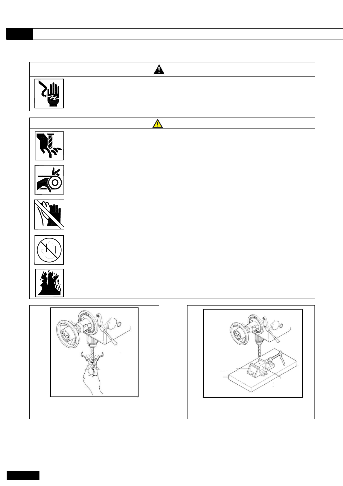
1. Operators should wear safety glasses, hat, shoes, etc.
Wearing gloves are dangerous.
2. Machine should be checked before use as fuel, cutting condition, tools equipped, clamps, etc.
3. 'Power up' should start with the order of the drive switch of power console panel and 'Power down' should
start with the reverse order
4. Please be aware of the location of the emergency stop switch
5. Do not touch spinning objects when it's spinning. Hands or fingers could get stocked or caught in the
machine.
6. Do not clean chips with bare hands. Use a brush or proper cleaner when the machine is completely stop.
7. Do not use the machine for other uses.
8. All label and pictogram should be kept clean and please contact the customer service when damaged for
new one.
9. Do not remove any protective devices.
Without protective devices, serious disaster could happen
10. For further safety details, please contact us.
▮Label number : PL-02

Operating Manual
NRD-1000
Nambuk Co.,Ltd
9
▮Label number : PL-03 ▮Label number : PL-04
WARNING PL-03
Turn off power
when repair
No wet hands
when switching.
Ground connection
required. Do not
ground onto
inappropriate place
like gas pipes.
▮Label location
안전 조작 사항
경 고 WARNING
경고 WARNING
고전압 감 전
PL-03
접 지
착용하십시오.
작업시 귀마개를
소음주의
경 고
경 고
제거하지 마십시오.
큰 상해를 입습니다.
회전체를 만지면
말릴 위험
경 고
말릴 위험
경 고
보호장비 착용
비산물과의 접촉은
부상의 위험과 실명을
유발할수 있습니다.
화상 위험있슴.
서비스전 필히 전원을
OFF하여 주십시오.
전기 위험
접촉시 전기적 충격/
경 고
안전 정보에 대한
설명서를 참조하십시오
조작할수 있습니다
허가된자만이 기계를
손대지 마시오.
위 험
이 기계를 사용하기전에
사용 설명서를 읽고 숙지 및
장비 지침을 따르지 않으면
이해한 후 사용하십시오.
상해를 입거나 장비에
손상을 일으킬수 있습니다.
사용 설명서 숙지
경 고
중량물 취급주의.
있으니 운 반장치 나, 2인
이상이 작업하십시오.
경 고
안전메뉴얼을 반드시 읽고 숙지하여 주십시오.
이 기계를 운전 하기 전에 취급설명서 및 경고라벨,
경 고
차단 및 잠금장치를
서비스전에 주 전원
체결하십시오.
위 험
정지하여 주십시오.
큰 상해를 입습니다.
말릴 위험
Entanglement

Operating Manual
NRD-1000
10
Nambuk Co.,Ltd
2-5. Safety Precautions
DANGER
wTurn off main power when opening the electric box.
w Do not switch when hands are wet.
WARNING
wDo not touch chips or spindle when operating(Do not touch with bare hand
even when stopped since the blades of the tool are sharp)
wDo not remove the safety cover during operating, it could cause your hands or
fingers get caught in the belt.
wDo not wear gloves, it could get caught in the spindle during spinning
wPlease keep away when it's stopped for power problem, power could
automatically get back on.
wOil-soluble cutting oil on clothing could be a fire hazard. Dry it completely
wUsing water-soluble oil for fire prevention, please be careful
Do not touch chips during spindle is
spinning.
Object should be firmly fixed using
vise
vise
table
processed
object

Operating Manual
NRD-1000
Nambuk Co.,Ltd
11
WARNING
wChips in the machine should be removed by a hook with safety glasses on after
the spindle is stopped completely.
wObjects you work on should be fixed firmly or they could pop up
wGround connection is required. Do not ground onto inappropriate place like gas
pipes.
wElectric Danger (High Voltage)
Turn off the main power off and lock the device. If you don’t, it could cause
electric shock or serious injuries.
wThe object you work on should be treated carefully. Falling down on your feet
could cause serious injuries
wElectric wiring should be connected to a power with ground fault circuit interrupter
wPlease keep away when it's stopped for power problem, power could automatically
get back on.
wDo not use the machine at the place around combustible gas
wPlease be aware of the location of the emergency stop switch.
wThe machine should be stopped completely for repair, parts exchange, check or
when notice of potential hazard
wAll parts should be installed at the appropriated place
wPlease inform the manager or person in charge when repair or check after the
machine stopped completely
wPlease check the machine and around if there is any possible hazard before turn
on the power.
wPlease read all instructions carefully prior to operate the Tapping Machine.
wDo not use the machine for other purposes.
wDo not overload
wDo not disassemble or convert.
wApplicable voltage or frequency (imprinted on motor) used only.
wApplicable electric fuses use only
Unapproved changing electric circuit diagram cause electric fault.
wOperators should wear safety glasses, hat, shoes, etc.
wPlease contact our customer service when safety covers damaged for new ones.

Operating Manual
NRD-1000
12
Nambuk Co.,Ltd
WARNING
wAfter using the machine, it requires cleaning and fueling.
Wipe the rusty parts with cutting oil.
wRegular repair and check required.
wOnly skilled workers operate the machine. A person who is not
well-informed about the machine could cause serious risks.
wDo not use when you are not certain about safety.
Unnecessary things or people around the work area could cause
unexpected accident.
wShut down the main power when blackout.
wShut down the main power when the machine is not used.
wThe machine should be installed firmly on a leveled place.
Please inform us when you need to move and reinstall the machine for
safety.
wProtective guards and personal protective equipments are required during
operating.
Unnecessary movement or motion could cause injuries as you could be
bumped into the operating machine.
wPlease clean all the grease or cutting oil on surface around work area.
wDo not overload. This could cause machine damage or unexpected risks.
wYou should lock up the machine when moving or operating.
wPlease inform us when you are noticed an expected hazard. The contact
information is on the manual and our website.
Do not remove the safety cover during
operating, it could cause serious injuries.
Personal protective equipments should
be worn when operating.
protection
guard

Operating Manual
NRD-1000
Nambuk Co.,Ltd
13
3. Product Description
3-1 Specifications
Specifications
Unit
NRD-1000
Capacity
Drilling capacity
Steel
mm
40
Cast iron
mm
50
Tapping capacity
Steel
mm
M25
Cast iron
mm
M32
Major
SPEC.
Diameter of column
(A)
mm
240
Distance center of spindle
Min (B)
mm
250
to face of column
Max (C)
mm
1000
Distance center of
(D)
mm
1285
column to end of arm
Distance base to
Min (E)
mm
280
spindle nose
Max (F)
mm
1100
Height floor to column cap
(G)
mm
1980
Max. height floor to top of
head
(H)
mm
2370
Base size (I×J×K)
mm
1600×700×160
Traverse of arm column
mm
600
Working surface of base
mm
1000×700
Net weight
kg
1700
Spindle
Diameter of spindle/quill
mm
65/80
Vertical traverse of spindle
mm
220
Taper of spindle
MT
#4
Number of feed speed
Step
9
Range of spindle speed (60Hz)
r.p.m
49-1524
Number of spindle speed
Step
3
Range of feed speed
mm/rev
0.11~0.33
Motors
Spindle drive motor
kw
2.2
Arm elevating motor
kw
0.75
Coolant pump
w
100
500A
C
D
B
400
24
650
42E
고정 너트 - TN22
G
F
42
18
I
G
A B
D
C
C
F
H
J
E
K
AB
E
G
F
D
0.22
N
0.11
0.33
N

Operating Manual
NRD-1000
14
Nambuk Co.,Ltd
3-2 Descriptions of each part of the machine
27
3
4
26
25
24
5
6
7
8
9
10
11 12
1
2
11
14
13
23
22
20
21
15 16 18 1917 2928
0.22
N
0.11
0.33
N
1.
Base
16.
Switch box
2.
Work table
17.
Spindle
3.
Column
18.
Handle for fine-feed
4.
No fuse braker S/W
19.
Rack for spindle box traverse
5.
Column sleeve
20.
Handle for spindle box traverse
6.
Clamp lever for column sleeve
21
Automatic manual feed change lever
7.
Arm
22.
Spindle box
8.
Clamp lever for arm
23.
Change lever for spindle feed speed
9.
Arm elevating screw
24.
Arm elevating motor
10.
Arm elevating reduction box
25.
Balance weight
11.
Oil level gauge
26.
Cover for arm
12.
Clamp lever for spindle box
27.
Coolant pump
13.
Spindle motor
28
Working light
14.
Change lever for spindle speed
29
Protective Guard
15.
Mono-lever S/W

Operating Manual
NRD-1000
Nambuk Co.,Ltd
15
3-3 Accessories
Standard
Accessories
Working table 410× 530× 400
set
Coolant system
1 set
Anchor bolts 5/8"× 400ℓ
1 set
Leveling plates & bolts
1 set
Tool box
1 ea
Allen wrench 2.5~14mm(10 kinds)
1 set
Double spanner 8 X 9 ~ 30× 32(6 kinds)
1 set
Adjustable wrench spanner 250mm
1 ea
Screw driver +,-
Each 1ea
Box spanner 24mm, 35mm
Each 1ea
Center Drifter
1 ea
Oil gun
1 ea
Drill chuck with shank(19mm)
1 set
Drill socket(M.T4× 3,2,1)
1 set
Protective Guard
1 set
Special
Accessories
Drill Tapper(Tap & drill guick change chuck)
1 set
Multi-spindle drill and tap unit
1 set
Set anchor(4EA)
1 set
4. Characteristics of Product
4-1. Spindle Box
The spindle box is located in the upper part of
the gear box, with the spindle feed and the
box-translation unit is installed in the lower part
of gear box, and each operating lever is
located in an easy-to-action position
4-2. Spindle
The spindle is made of chrome-molybdenum
steel with heat treatment. Precision grade roller
bearings and thrust bearings are assembled to
maintain high accuracy even during heavy
loads. In addition, spindle sleeves are made of
chrome molybdenum steel by heat treatment
and are excellent in durability and abrasion
resistance to maintain machine precision for a
long time.

Operating Manual
NRD-1000
16
Nambuk Co.,Ltd
4-3. Spindle driving gear
Every kind of gear and shaft is made by
carburizing heat-treatment with
chrome-molybdenum steel and the ground,
which ensures enough strength. Automatic
oiling system to Bearings and Gear let
Gear maintain smooth power transmission.
4-8. Column & Sleeve
Column is vertically assembled on Base by fitting
Column Sleeve outside, which allows Arm to elevate
through flesh side. The center between Column and
Sleeve is supported by Ball Bearing and Thrust
Bearing at upper part and Roller at lower part,
which allow Arm to easily rotate.
4-9. Arm
Arm is fitted vertically to Column for elevating.
Since Slide surface on which Spindle Box is
traversed is heat-treated followed by grinding,
which ensures excellence in durability and
abrasion-resistance. Behind Arm, Clamps for each
part and electric control box is equipped, and at
lower part of Arm, work light is built in.
4-10. Electric control Box
It protects Machine With over-load relay and relay
for prevention against reverse increase.
4-4. Feed gear
Every kind of Gear and Shaft is made by
carburizing hear-treatment with
chrome-molybdenum steel and the ground.
one set of Worm Gear and Overload safety
Device is equipped.
4-5. Spindle Speed Change
One levers will allow you to easily
change speed by 9 stages and to make
spindle forward-reverse rotated.
4-6.Feed Speed Change
One levers perform speed change by 3
stages.
4-7. Base
Base is for fixation of work structure. It
has three T-slot, coolant slots at the
edge of work level and at the base column
equipped, coolant tank is installed
4-11. Arm elevation Box
Arm elevating Box is equipped on Column Sleeve. Worm
is elevated by motor and Arm is elevated by Worm
Gear and Screw. Overload safety device protects
machine.

Operating Manual
NRD-1000
Nambuk Co.,Ltd
17
5. Transportation and Installation of Machine
5-1. Transportation and Unload Machine
◆Machine Unloading Method
During movement, transportation and unloading of
this machine, please put down the arm to the lowest
level, the spindle box at position ⓑ, the working
table at position ⓐ, adjust ⓔ zig at ⓒ, ⓕ zig at
the end of the T groove, and fixate the spindle box,
arm, and column sleeve completely.
Please adjust a strong enough rope or other
instrument to the center of the machine as shown in
the following picture and use protection pads like a
thick fabric to prevent the rope from directly touching
the slideway face of the arm. Before lifting up the
machine, please recheck the centers of the rope and
machine.
◆Transportation Method of Machine
During transportation of the machine, please adjust
the center equivalent to the unloading method, fixate
the arm and column sleeve firmly, use protection
pads like a thick fabric to protect the machine as
shown in the picture with strong enough rope, and
fixate the machine firmly as shown in numbers 1, 2,
3, and 4 in the picture to transport.
Please make sure to inquire or request us in advance during transportation and installation.

Operating Manual
NRD-1000
18
Nambuk Co.,Ltd
5-2. Wiring
Connect Electric Power source, R.S.T to
terminals. After power on, press “NO”switch in
front of machine, and Pilot Lamp will be lighted
up. In case of not being lighted up, two lines
among three lines of power source should be
exchanged.
☆ Be sure to ground the Earth.
5-3. Product Installation
This machine is able to demonstrate its capability if enough installation space is secured on
the solid ground for convenient work and maintenance.
For the foundation, please increase or decrease the thickness of the concrete according to the
ground in order to prevent sinking or generating cracks due to the weight of the machine and
processed object. For the installation area, please avoid direct sunlight and install without
any vibration.
The foundation shall be accompanied by the following basic drawing.
Power Source
Terminal
no fuse braker
leveling plate

Operating Manual
NRD-1000
Nambuk Co.,Ltd
19
5-4. Balance of Product
Balance of the machine is very important to
maintain its processing precision and
durability.
When the machine is initially installed, if it
is hard to maintain balance due to long period
of packing condition or a deformation generated
during transportation and unloading, please
carry out balance work in several weeks after
installation.
Also, in order to maintain the precision of the
machine, please check the balance condition of
the base periodically.
Work Method
⦁ After fitting leveling plate to foundation
bolt, lift machine to fit it to slot of leveling
bolt attached on base and then fasten washer and
nut.
⦁ After machine is installed on foundation, put
level on Base followed by adjusting the level and
then fill concrete or mortar around Foundation
Bolt.
⦁ After foundation is completely hardened, be
sure to set the leveling more exactly.
⦁ After foundation is completely set, remove
rustproof oil applied on workable parts of
machine and then apply machine oil or the same
kind of oil on slide surface of Arm, Column
Sleeve, etc.
⦁ please supply machine with oil as instructed
in oiling list.
⦁ By connecting electric lines, put Arm on the
center of Column Sleeve and Spindle Box on the
center of Arm, and then clamp Spindle Box and
Column Sleeve.
⦁ Firstly, put the Level in unit of 1/100 mm/m
position to right and left by adjusting with
Leveling Bolt. If there is not and problem,
gently tighten Foundation Bolt in consecutive
order. If leveling is well done, please tighten
it fully.
⦁ Leveling should be adjusted as much as the
center of Base is formed concave. When horizontal
is finished, put a cover over the place of
Foundation Bolt of Base.
5-5 Fueling
To maintain durability and function of machine
for a long time, please check oiling condition
periodically and be careful not only to use oil
appointed but also to keep oiling times and that
to be exchanged.
Before operating machine, be sure to check oiling
list.
5-6 Spindle Box
Lubrication of the spindle box lubes through the
plug on the top of the spindle box cover, and
the exhaust is through the plug under the back
of the spindle box.
The oil flow should be at the center of the oil
level on the front of the spindle box(when the
machine is operating).
The gear and bearings inside the spindle box are
forcible circulation by the trochoid pump.
When operating the spindle box, be sure to
confirm the lubrication condition with the fluid
on the left side of the box from time to time.
5-7 Arm Elevating
Lubrication and discharge through the plugs on
the upper and lower arms of the upper and lower
arms. The fueling amount should be at the center
of the oil level on the front of the box. Fill
the arm and column sleeve with lubricant once a
day through two ball caps on the back of the arm.
☆To the other places to be oiled, please follow
as oiling list and oiling diagram.
leveling bolt
foundation bolt

Operating Manual
NRD-1000
20
Nambuk Co.,Ltd
Oiling List
Mark
Places to be oil
Oil volume
Oil Time
Oil Recommended
A
Spindle Box
Approx. 2ℓ
First 3 months,
Exchange every 6
months ever since
MOBILL D.T.E OIL LIGHT
A 1
Spindle Box Refueling Oil cup
B 1
Grease nipple of lower edge of spindle
sleeve
Properly
every 3 months
MOBILL MOBILUX GREASE
NO. 2
C 1
Arm Elevating Box
Approx. 0.5ℓ
every 6 months
SHELL TELLUS OIL 27
D
Column Sleeve Slide Surface
Properly
once per day
MOBILL
D 1
Column Sleeve Slide Surface
Lubrication ball cap(2parts)
E
Arm Elevating Screw Refueling oil cup
Properly
once per week
VACTRA OIL NO. 2
E 1
Arm Elevating Screw Refueling oil cup
F
Slide surface of Arm
Properly
once per day
SHELL
G
The others
Properly
once per day
MOBILL
* The oil supply periods were set taking into account the oil component on a basis of an 8-hour operation per
day. As each oil’s life is affected by many factors such as change of viscosity resulting from
the conditions of use, environment (temperature, humidity, etc.), and oil deterioration,
be sure to determine the exchange period after checking the oil conditions.
Oiling Diagram
Table of contents
Other Nambuk Drill manuals