Nic SC-5 User manual

Sample Changer
SC-5
Instruction Manual
NIC-TD-0000008-04
Nippon Instruments Corporation

Instruction Manual: Sample Changer SC-5 NIC-TD-0000008-04
Nippon Instruments Corporation
Table of Contents
1. Introduction................................................................................................................. 1
1.1. Safety precautions................................................................................................. 1
2. Outline of instrument ................................................................................................. 2
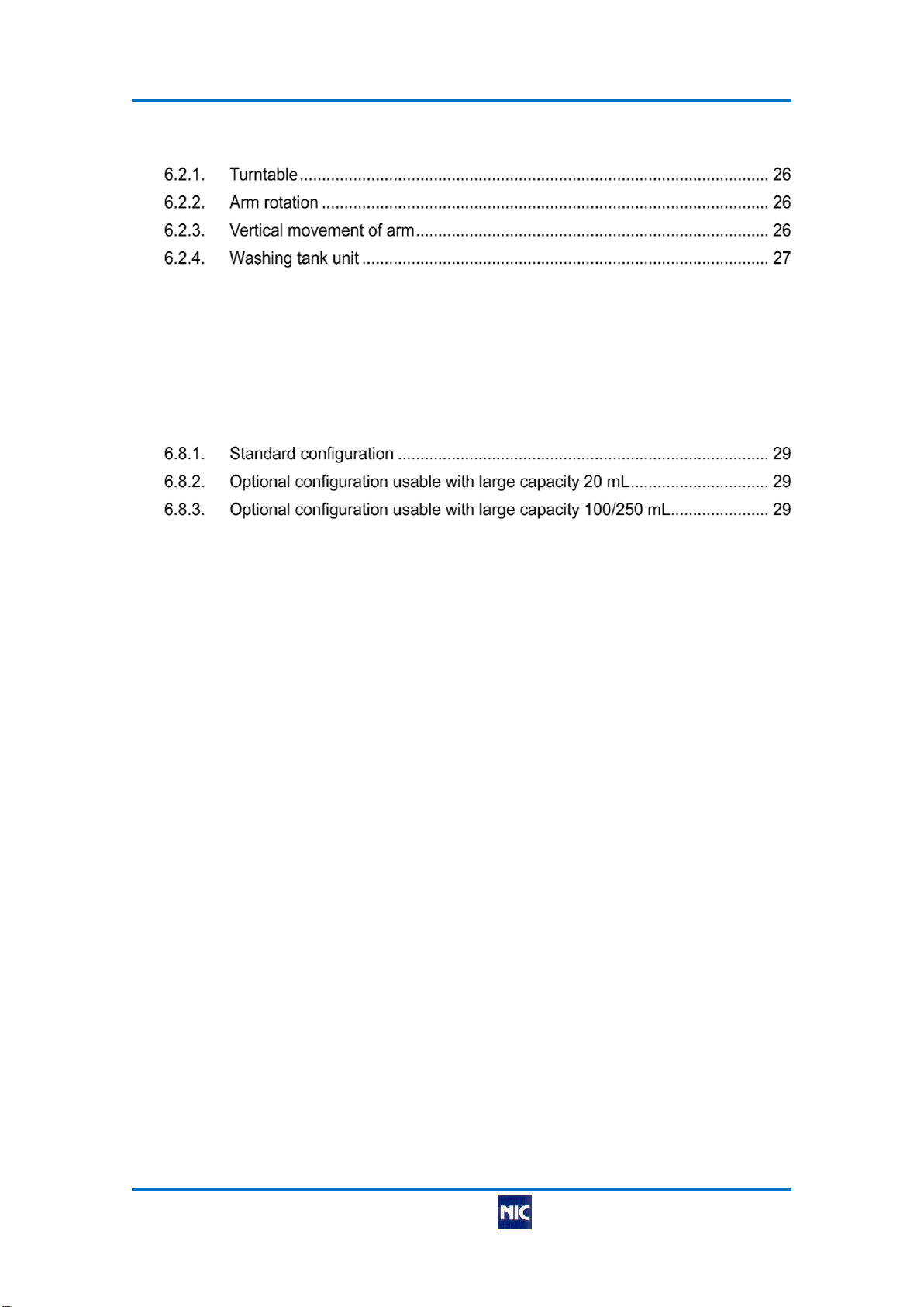
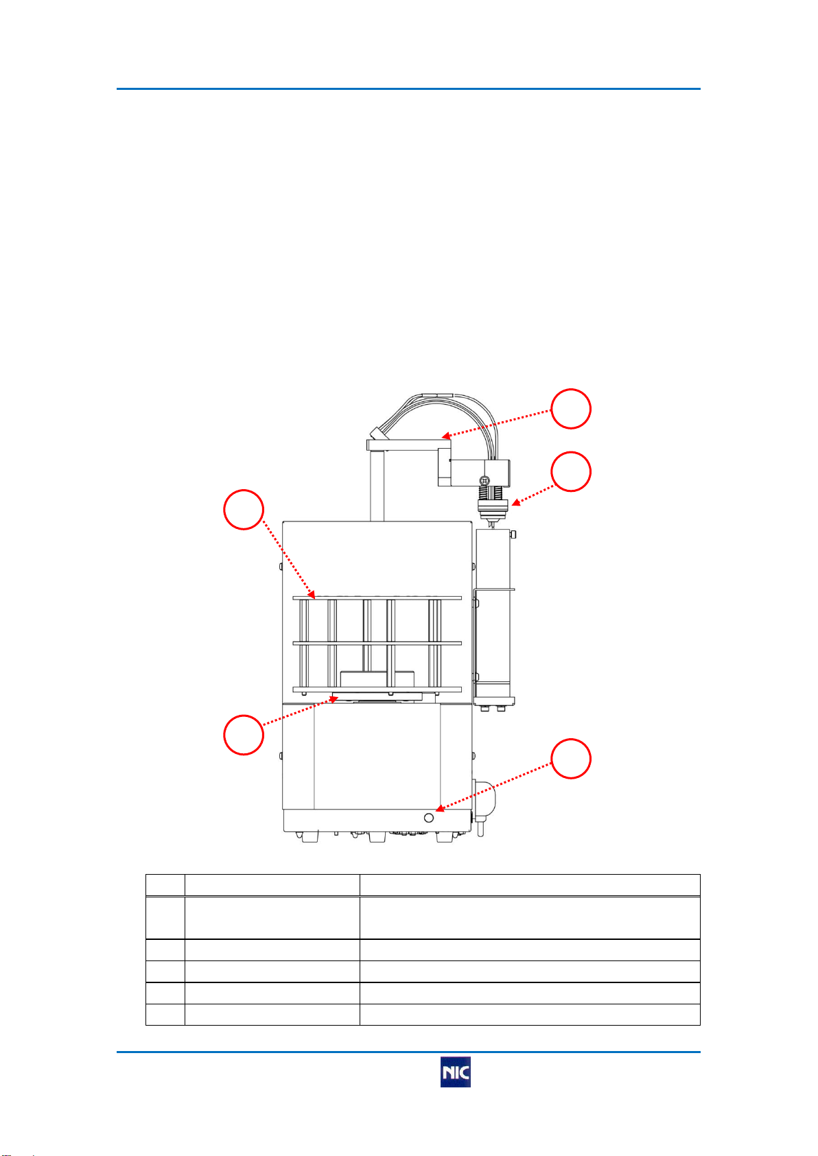
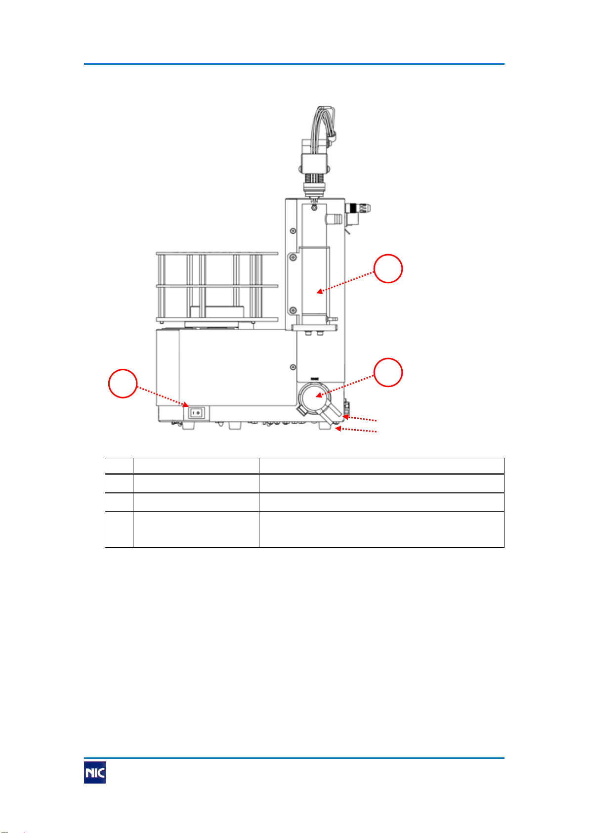
2.1. External appearance of instrument....................................................................... 2
3. Installation and connection....................................................................................... 6
3.1. Installation of instrument ....................................................................................... 6
3.2. Fixing of cap unit (standard: 5mL) ........................................................................ 6
3.3. Fixing of cap unit (option: large capacity) ............................................................. 7
3.4. Connection on rear side ........................................................................................ 8
3.5. Fixing of table ........................................................................................................ 9
3.6. Fixing and adjusting of washing tank and rinse sleeve ...................................... 10
3.7. Connection of pure water tank and effluent tank ................................................ 12
3.8. Connection to main detector and RD-5 .............................................................. 12
4. Startup and shutdown.............................................................................................. 13
5. Maintenance .............................................................................................................. 13
5.1. Daily inspection ................................................................................................... 13
5.2. Time-change components................................................................................... 14
5.3. Yearly inspection ................................................................................................. 15
5.4. Replacement of components .............................................................................. 16
6. Detailed specification............................................................................................... 26
6.1. General performance .......................................................................................... 26

Instruction Manual: Sample Changer SC-5 NIC-TD-0000008-04
Nippon Instruments Corporation
6.2. Performance of each part.................................................................................... 26
6.3. Specification of external connection ................................................................... 27
6.4. Dimensions and weight ....................................................................................... 27
6.5. Power supply....................................................................................................... 27
6.6. Standard accessories.......................................................................................... 28
6.7. Options ................................................................................................................ 28
6.8. External appearance of instrument configuration ............................................... 29
7. Installation requirements......................................................................................... 30
7.1. Atmosphere ......................................................................................................... 30
7.2. Power requirements ............................................................................................ 30
7.3. Measures against electric noise.......................................................................... 30
8. Warranty .................................................................................................................... 31
8.1. Warranty period and relevant item...................................................................... 31
8.2. Warranty terms.................................................................................................... 31
9. Precautions concerning disposal of instrument................................................... 31
10. Contact address........................................................................................................ 32

Instruction Manual: Sample Changer SC-5 NIC-TD-0000008-04
Nippon Instruments Corporation 1
1. Introduction
1.1. Safety precautions
To use this product safely, observe the following precautions.
Nippon Instruments Corporation will not take any responsibility for accidents
caused by a user's carelessness.
Meanings and descriptions of symbols
In the case of mishandling, a user may be killed or suffer a
serious injury immediately.
In the case of mishandling, a user may be killed or suffer a
serious injury.
In the case of mishandling, a user may suffer an injury or
material damage is expected.
* Using this product involves no risk corresponding to "Danger".
Cautions concerning installation
Observe the installation requirements and power
requirements, or a failure may occur.
Install the instrument on a horizontal working table with
sufficient strength, or a slight injury or a failure caused by a
fall or a drop may result.
Cautions concerning handling
Before using a reagent, procure and administer the safety
data sheet (SDS).
When using a reagent, wear protective equipment and carry
out ventilation sufficiently. Reagents to be used for the
instrument include acute toxic and corrosive substances.
Do not disassemble or modify the instrument without
permission, or a failure may result.
Read this document carefully before using the instrument, or
a failure caused by an operational mistake may result.
Observe the range of the specification, or a failure may
result.
Do not operate the instrument with a wet hand.
Cut off the power supply before carrying out maintenance
work, or a failure caused by a short circuit may result.
Dispose of effluent appropriately after using the instrument.
Do not touch any driving unit intentionally. An injury is not
likely to occur because the speed and torque are low, but a
failure of the instrument may result.
Danger
Warning
Caution
Caution
Warning
Caution

Instruction Manual: Sample Changer SC-5 NIC-TD-0000008-04
2 Nippon Instruments Corporation
2. Outline of instrument
The sample changer SC-5 is an optional instrument for the reducing vaporization
mercury analyzer RA-5 or fully automatic heat vaporization mercury analyzer MA-
3000.
This instrument enables the automatic exchange of sample containers and the
automatic cleaning of the bubbler according to instructions received from the main
detector (RA-5 or MA-3000) in order to ease the user's burden and support analyses
with good reproducibility.
2.1. External appearance of instrument
2.1.1. Front
No.
Name
Description
1
Table
This is a turntable on which to set sample
containers.
2
Table holder
This is a holder for the positioning of the table.
3
Cap unit
Seals a sample container.
4
Arm
Holds the cap unit, moves vertically and turns.
5
Power pilot lamp
The blue lamp lights when the power is turned on.
1
2
3
4
5

Instruction Manual: Sample Changer SC-5 NIC-TD-0000008-04
Nippon Instruments Corporation 3
2.1.2. Right side
No.
Name
Description
1
Power switch
This turns on and off the instrument.
2
Rinse pump
This is a pump to supply pure water for cleaning.
3
Washing tank
The bubbler is washed using pure water supplied
from the rinse pump.
3
2
1
Rinse pump outlet side
Rinse pump inlet side

Instruction Manual: Sample Changer SC-5 NIC-TD-0000008-04
4 Nippon Instruments Corporation
2.1.3. Rear
No.
Name
Description
1
Communication
connector
To be connected to the main detector using the
supplied communication cable.
2
DC jack
The supplied AC adapter is connected.
3
Circuit protector
This is an overcurrent protection device.
4
Seal sensor connector
The seal sensor of the cap unit is connected.
5
Clamp
Tubes of the cap unit are passed.
3
2
1
5
4

Instruction Manual: Sample Changer SC-5 NIC-TD-0000008-04
Nippon Instruments Corporation 5
2.1.4. Upper face
No.
Name
Description
1
Table shaft
This is a rotation driving shaft. The table holder is
attached.
2
Shaft cap
Covers an unused shaft to protect the inside.
1
2
Table shaft for standard
capacity (5 mL)
Table shaft for optional
large capacity

Instruction Manual: Sample Changer SC-5 NIC-TD-0000008-04
6 Nippon Instruments Corporation
3. Installation and connection
3.1. Installation of instrument
Observe the installation requirements, or a failure may occur.
Install the instrument on a horizontal working table with
sufficient strength, or a slight injury or a failure caused by a
fall or a drop may result.
Do not operate the instrument before installation and
connection are all completed.
1) Put the SC-5 in the installation position. When installing on the stand of the RD-5,
see the instruction manual of the RD-5.
2) Connect tubes and cables according to the following sections.
3.2. Fixing of cap unit (standard: 5mL)
Check that each tube is not wet or dirty.
Attach the cap unit to the arm using two M4 hexagon socket head cap screws and two
washers.
When attaching, push in the direction of the arm rotation axis (direction of the arrow),
and determine the position.
Caution
Caution
Arm
Hexagon socket head cap screw
Washer
Cap unit
Arm cover F
Seal packing
Bubbler
Screw fixing cover
(Also on opposite side)
Arm cover R
Arm rotation axis
Direction for pushing cap unit

Instruction Manual: Sample Changer SC-5 NIC-TD-0000008-04
Nippon Instruments Corporation 7
3.3. Fixing of cap unit (option: large capacity)
Check that each tube is not wet or dirty.
1) Remove the rinse sleeve from the washing tank.
2) Attach the cap unit to the arm in similar procedure of “5mL”.
3) Through the sensor cable to nylon clamp, and then fixed by M4 screw to the arm
with the tube holder.
4) Secure the reaction tube to both clamp (φ13) and (φ16).
5) Connect to the reaction tube to the main detector (RA-5 or MA-3000), and then
make sure the reaction tube move smoothly without any catch when the vertical
movement of the arm.
Caution
Reaction tube
Clamp (φ13)
Tube holder
Nylon cramp
M4 screw
Sensor cable
Clamp (φ16)

Instruction Manual: Sample Changer SC-5 NIC-TD-0000008-04
8 Nippon Instruments Corporation
3.4. Connection on rear side
1) Connect the supplied SCIF cable to the communication connector, and connect
the other side to the main detector.
2) Connect the AC adapter output plug in the accessories to the DC jack.
3) Connect the AC adapter to the outlet with the ground.
4) Connect the seal sensor of the cap unit to the seal sensor connector.
Continue to perform the following tasks in the case of 5mL cap.
5) Pass the cap tubes and the cable of the seal sensor through the nylon clamp, and
fix it to the arm using an M4 screw. In the case of the optional large cap, pass only
the cable of the seal sensor.
6) Pass the cap tubes through the clamp.
Nylon clamp
Reaction tube
Seal sensor cable
Clamp
AC adapter
output plug
Communication cable
M4 screw

Instruction Manual: Sample Changer SC-5 NIC-TD-0000008-04
Nippon Instruments Corporation 9
3.5. Fixing of table
1) As shown above, insert the table holder into the table shaft according to the
sample container and table to be used. Check that the table holder and the table
shaft engage correctly.
2) Cover the unused shaft with the shaft cap.
3) Align the guide pins of the table holder with the locating holes in the table, and set
the table on the table holder.
Standard
(5 mL sample container)
Option
(Large sample container)
Guide pins
(3 places)
Table
holder
Shaft cap
Shaft cap
Table
holder

Instruction Manual: Sample Changer SC-5 NIC-TD-0000008-04
10 Nippon Instruments Corporation
3.6. Fixing and adjusting of washing tank and rinse sleeve
Fix the washing tank to the washing tank holder using two M4 hexagon socket head cap
screws and two washers.
It is possible to change the directions of the joints for effluent and pure water to three
angles, as shown in the figure.
Select the angle according to the layout of the working table.
When using the standard cap unit (5 mL), attach the supplied rinse sleeve and insert it
with its locating bolt aligned with the locating notch in the washing tank.
* When using the optional large cap, be sure to remove the rinse sleeve.
M4 hexagon socket head cap screws
and washers
Locating notch
Rinse sleeve
Locating bolt
M4 hexagon socket head cap screws
and washers
Pure water joint
Effluent joint
Washing
tank
Washing tank
holder
On shipment
-45rotation
-90rotation

Instruction Manual: Sample Changer SC-5 NIC-TD-0000008-04
Nippon Instruments Corporation 11
Adjust the position of the washing tank in the following procedure.
1) After initialization, lower the arm to the rinse position.
2) Loosen M4 hexagon socket head cap screws, so that the washing tank center will
meet the cap portion center, to adjust the position of the washing tank holder.
Also adjustment of the right and left direction is done by loosening the M4 resin
screws.
Washing tank
M4 resin screws
M4 hexagon socket
head cap screws
Washing tank holder
Left/Right
direction

Instruction Manual: Sample Changer SC-5 NIC-TD-0000008-04
12 Nippon Instruments Corporation
3.7. Connection of pure water tank and effluent tank
1) Pour the necessary quantity of pure water for washing into the pure water tank,
and close the lid.
2) Connect the pure water inlet tube to the washing pump inlet side.
3) Connect the pure water outlet tube to the washing pump outlet side, connect the
other side to the pure water joint of the washing tank, and fix them using supplied
cable ties.
4) Connect the drain tube to the washing tank effluent joint, and fix it using a supplied
cable tie. Insert the other side in the hole in the lid of the effluent tank, and attach
two supplied cable ties to prevent the tube from coming out.
*Effluent is drained to the effluent tank from the washing tank by the natural fall.
Because effluent will not be drained if the tip of the drain tube is soaked in effluent,
fix the tip of the drain tube in the position immediately below the lid of the effluent
tank, as shown in the figure.
3.8. Connection to main detector and RD-5
See each instruction manual and carry out connection job.
Cable ties
Cable ties
Pure water outlet tube
Pure water inlet tube
Pure water tank
Effluent tank
Effluent tube

Instruction Manual: Sample Changer SC-5 NIC-TD-0000008-04
Nippon Instruments Corporation 13
4. Startup and shutdown
1) Check that the supplied AC adapter has been connected to the outlet with the
ground, and turn on the power switch of the SC-5.
2) The initialization (return to origin) and various control operations are carried out
through communication with the main detector.
For details, see the instruction manual of the upper instrument.
3) After the termination process commanded by the main detector is completed, turn
off the power switch of the SC-5.
5. Maintenance
5.1. Daily inspection
Item
Inspection standard
Communication
cable
1) Should be connected to the main detector and RD-5.
2) Should be fixed to the connectors using the screws of the
communication cable.
Power supply
1) The output plug of the AC adapter should be connected to the DC
jack.
2) The AC adapter should be connected to an outlet with the ground.
Reagent tubes
1) Any connection should not be disconnected.
2) Any tube should not be bent or clogged.
3) The tubes should be filled with reagents.
4) The protrusion of the tube should be right length.
Washing tank
1) Tubes should be connected to the pure water joint and effluent
joint.
2) Tubes should be fixed using cable ties.
3) When the standard cap (5 mL) is used, the rinse sleeve should be
installed in the washing tank.
4) When the large cap is used, the rinse sleeve should be removed.
Pure water
tank
1) The pure water tank should have the necessary quantity of pure
water.
2) Any tube should not be bent or clogged.
Effluent tank
The effluent tank should be empty.
Table holder
Should be installed in the predetermined position.
Shaft cap
The shaft cap should be attached to the unused shaft.
Table
1) The table suitable for the sample container should be installed.
2) Should not be dirty or shaky.
Instrument
startup
The initialization (return to origin) should be carried out normally when
the instrument is started.
* The initialization is carried out by the command of the main detector.

Instruction Manual: Sample Changer SC-5 NIC-TD-0000008-04
14 Nippon Instruments Corporation
5.2. Time-change components
We recommend that the following components be replaced periodically to use the
product stably, though their lifetimes vary depending on the usage condition:
Item
Exchange period and replacement procedure
Rinse pump tube
Replace a tube approximately one year or 2,000 hours after the
start of use.
If any abnormality in a tube such as a crack is found, replace it
even before the above period expires.
Replacement procedure
1) After carrying out the washing operation and draining pure
water in the flow path, disconnect the pure water inlet and outlet
tubes according to “3.6. Connection of pure water tank and
effluent tank”.
2) Turn the pump cassette counterclockwise and pull it toward you
to remove it.
3) Pull the hook of the tube holder in the direction of the arrow,
and remove the tube holder.
4) Pull out the rotor and tube from the cassette.
5) Apply silicone grease on the illustrated range of the new tube
and the shaft of the cassette.
6) Attach to the cassette the tube and rotor on which silicone
grease has been applied. Check that the tube has been caught
in the gap between the rollers and the cassette.
7) Attach the tube holder.
8) Insert the cassette and turn it clockwise until it is locked.
9) Attach the pure water inlet and outlet tubes as before.
Rinse pump
Replace the rinse pump approximately three years or 3,000 hours
after the start of use.
If there is an abnormality such as an abnormal sound during
rotation, replace the rinse pump even before the above period
expires.
Replacement procedure
1) After carrying out the washing operation and draining pure
water in the flow path, disconnect the pure water inlet and outlet
tubes.
2) Catch the hook with your finger, pull it out toward you and
remove the connector.
3) Connect the connector of the new pump to that of the main unit,
catch the hook in the notch in the main unit, and push it in.
4) Insert the pure water inlet and outlet tubes as before.
Effluent tank
Replace the effluent tank approximately one year after the start of
use.
* The recommended exchange period is not the guaranteed lifetime.

Instruction Manual: Sample Changer SC-5 NIC-TD-0000008-04
Nippon Instruments Corporation 15
●Removal and attachment of pump cassette
●Removal and attachment of pump tube
5.3. Yearly inspection
To use the product stably for a long period of time, we recommend that the instrument
be sent back for annual maintenance.
In the sending back maintenance, the replacement of time-change components, repair,
adjustment and performance check are carried out.
When pump cassette is removed
When pump cassette is attached
Hook
Pump cassette
Tube holder
hook
Pull.
Rotor
Tube
Cassette
Shaft
Tube
Range for application of grease
Cassette
Roller
The tube should be
caught in the gap
between the rollers
and the cassette.

Instruction Manual: Sample Changer SC-5 NIC-TD-0000008-04
16 Nippon Instruments Corporation
5.4. Replacement of components
Bubbler (standard: 5 mL)
1) Referring to "3.2. Fixing of cap unit", remove the screws fixing the cover and
remove the arm covers F and R.
2) Hold the PharMed tube for the bubbler tube, and pull it up with the bubbler.
3) Pull the PharMed tube out of the bubbler.
4) Pull the bubbler out of the cap unit.
5) Insert the new bubbler in the cap unit, and make the bubbler inserted in the
PharMed tube for the bubbler tube (insertion depth: 10 mm).
6) As shown in the figure, adjust the position of the bubbler so that it is set at 108+/-1
mm from the tip of the cap.
7) Attach the arm covers F and R as before.
Seal packing (standard: 5 mL)
Pull out the packing downward and attach a new one. The packing has a smooth
surface and a sponge surface. Attach it with the smooth surface placed downward.
PharMed tube
Cap unit
Bubbler
Seal Packing
(Place the smooth
surface downward.)
Bubbler tube

Instruction Manual: Sample Changer SC-5 NIC-TD-0000008-04
Nippon Instruments Corporation 17
Cap unit tubes and seal sensor (standard: 5 mL)
1) Carry out the reagent collection using the main detector.
2) Turn off the main detector and sample changer.
3) Loosen the two resin screws and remove the cap unit cover.
4) When replacing the seal sensor, remove the two resin screws fixing the sensor, and
remove it from the arm block.
Loosen the three resin screws and separate the arm block and the cap unit.
5) Loosen the three resin screws of the cap unit.
Cap unit cover
Resin screw
(also on opposite side)
Cap unit
Resin screw (3 places)
Seal sensor
Resin screw for fixing sensor
(2 places)
Arm block
Resin screw
(3 places)