Nigel Lawton 009 20HP WD Simplex Petrol Mechanical Loco Kit User manual
1
Credits
This kit has been a long time in the making and I would like to thank several fellow modellers for their help and advice along the way.
Pete Wilson for the original choice of exactly which Simplex to model, motivation to keep going and the use of his excellent layout ‘Willesden Junction’ to run and photograph development locos.
Dave Gibbs for his huge efforts in photographing and measuring up a prototype loco under rebuild allowing me to hopefully produce an accurately modelled set of bonnets and radiator in particular
(but many other details as well).
Phil Robinson for taking photos of the MRT loco for me.
Otto Shouwstra for being the original inspiration to use belt drives on a Simplex model and later advising me on reduction mechanisms leading to the two-stage friction drive.
Neil Moss for some excellent ideas on how to design etched brass kits particularly the use of sacrificial tabs and strengthening sections, and the final swinging arm design.
Neil Sayer for his enthusiasm in building the first complete loco (even before I had) and for many helpful suggestions as to how to improve the kit and instructions.
Ted Scannell and the P4 CLAG group for some brilliant insights into the issues around miniature drives using micro motors and belts which were instrumental in the evolution of the final drive design.
I am tempted to add my entire extended family at this point and shed an insincere tear Oscars style but am trying to resist…..
WARNING! ETCHED PARTS CONTAINED IN THIS KIT HAVE SHARP POINTS, EDGES AND CORNERS. HANDLE
ALL ETCHED PARTS WITH CARE AND REMOVE SHARP EDGES FROM THE COMPLETED MODEL.
WHITEMETAL SUPPLIED WITH THIS KIT CONTAINS LEAD – PLEASE DO NOT INGEST!
PLEASE READ ALL THESE INSTRUCTIONS THROUGH BEFORE STARTING TO BUILD THE KIT.
IT IS IMPLICIT THAT ALL JOINING PIECES ETC SHOULD BE REMOVED FROM ETCHED COMPONENTS BEFORE ASSEMBLY.
THIS KIT CONTAINS MANY SMALL PARTS. PLEASE TAKE CARE NOT TO LOSE THESE PARTS. SOME SPARES ARE PROVIDED
WITHIN THE FRETS IN CASE OF LOSS AND FURTHER REPLACEMENTS ARE AVAILABLE BY MAIL INITIALLY FOR POSTAL COSTS
ONLY.
NOTE THAT NOT ALL HALF ETCHED LINES IN THIS KIT ARE FOLD LINES, CHECK THE INSTRUCTIONS BEFORE FOLDING!
Tools Required
Small hobby knife or scalpel with new blade.
Soldering iron (preferably temperature controlled)
Flat thin nosed pliers long and short for folding, also a folding jig is nice
to have but not essential.
Small and larger round nosed pliers
Side cutters or snips for stripping wires
Small needle files for cleaning up parts.
Tapered Jeweller’s broaches
0.4mm,0.6mm, 0.8mm,1mm & 1.5mm drill bits with pin vice(s).
Mini drill with diamond disk or slitting disk and burrs.
General Assembly Notes
Cutting parts from the frets.
Use a sharp knife or scissors or special fret scissors. Apply knife side to side, not downwards. Where possible cut the trace at the opposite end to
where it joins the part and trim with scissors afterwards. Use fine needle files or toolmakers stones to clean up small projections.
Solder, use of flux and tinning
I recommend the use of 140C solder for most of this kit, including the majority of the detail parts. Do not use superglue, detail parts can be fixed
using quick set metal type metal epoxy (which is holds position better) if you do not want to solder them. Using 140C solder enables only a small
area of the kit to be heated and the heat-up and cool down times are much shorter. Always apply a small amount of flux before applying or re-flowing
solder. To tin parts apply a small amount of flux then carry a very small amount of solder to the part with the soldering iron. Repeat if more solder is
needed, but use the minimum amount to coat the surface in the thinnest possible layer. If too much is applied use the iron to take this elsewhere on
the fret (to other parts needing to be tinned or onto fluxed frame areas).
Consumables Required
Standard 240 degree solder
140 degree detail solder
Low-melt 70 degree solder
Flux (I recommend a paste type like ‘Powerflux’)
Non-permanent thread lock (e.g. Blue Loctite 242or green 603)
Quick set metal type metal epoxy glue
Model grease or oil
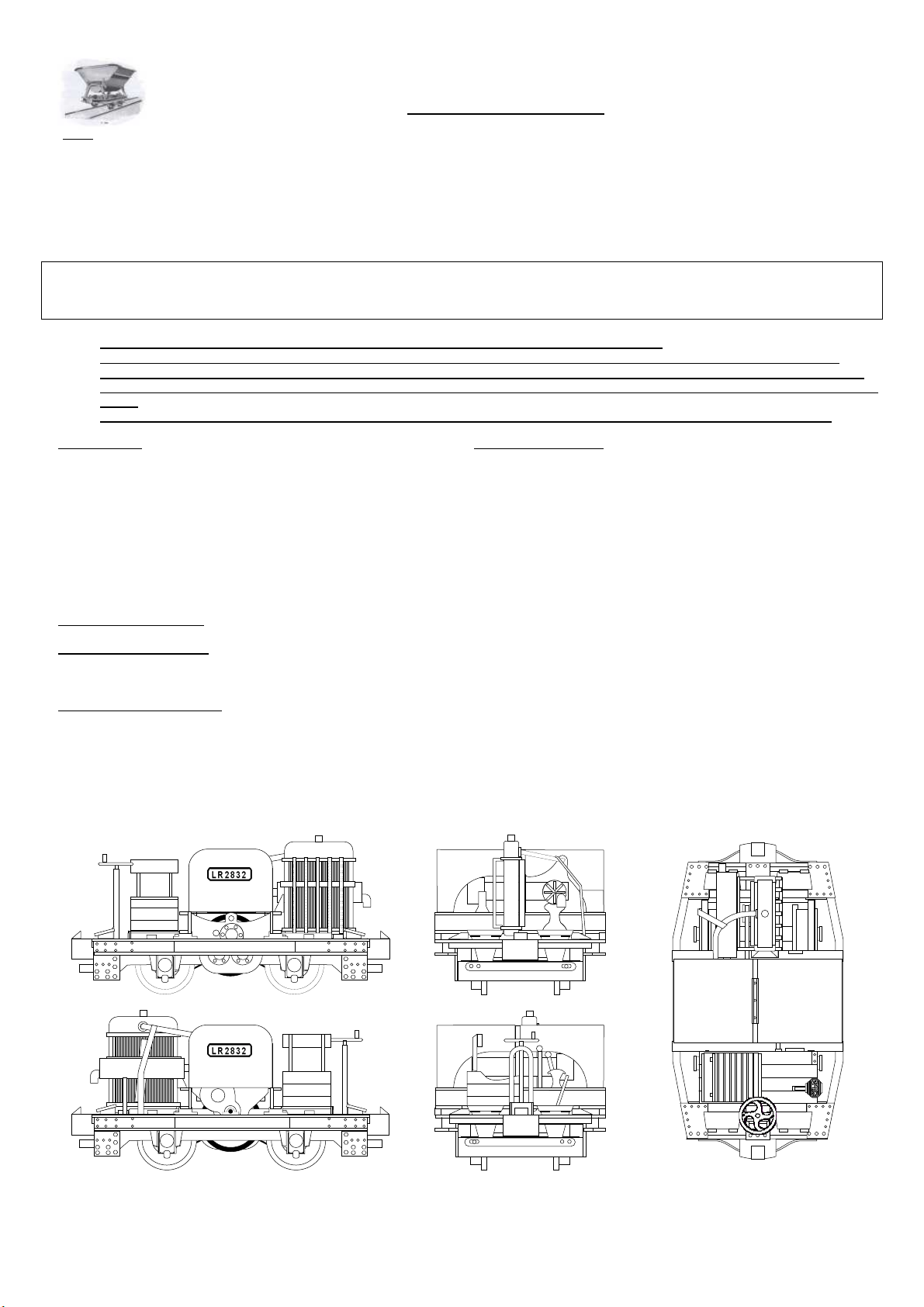
Nigel Lawton 009 20HP WD Simplex Petrol Mechanical Loco Kit
Assembly Instructions
2
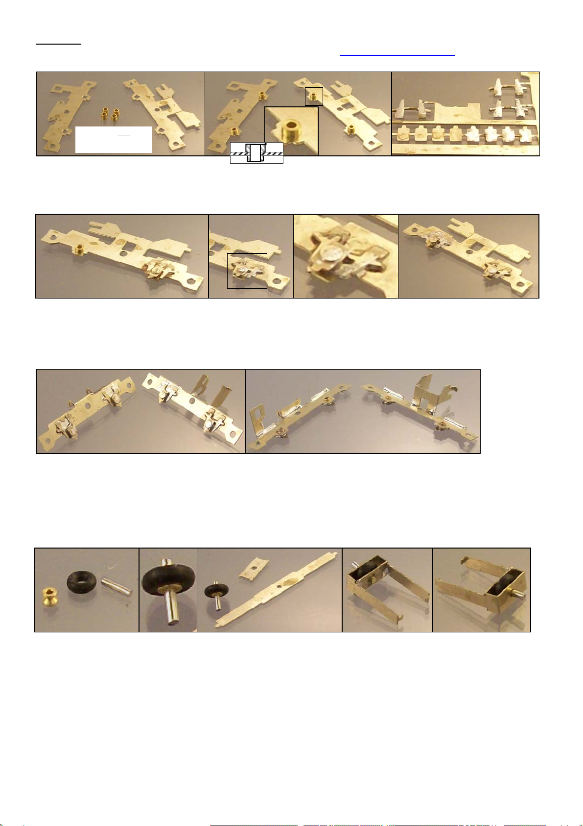
Take the main frame mechanism side A1 and fold the two small tabs with the half etched lines on the inside of the joins. Fold the large tab and
its wings with the half etched line on the inside of the folds. Run solder down the inside of these folds to reinforce them. Using small round
nosed pliers shape the two hooks. Take the main frame pickups side A2 and fold the two small tabs with the half etched lines on the inside of
the joins. Fold the large tab with the half etched line on the inside of the folds. Fold the two small tabs with holes with the half etched lines on
the inside of the folds. Run solder down the inside of these folds to reinforce them. Don’t worry if you fill the holes in the small tabs on A2 get
blocked with solder, just open them back up again with a 0.8mm drill. Its important to reinforce these small tabs particularly well. Wash the two
frame assemblies in fairy liquid and hot water to remove flux residues.
Take the 1.2mm root 2.2mm OD pulley I (not to be confused with the 2.5mm pulley W which is thinner and has a smaller centre hole) and fit the
4.4mm OD x 1.6mm cross section O ring J over the pulley. Take the 5mm length of 1mm shafting K and fit the pulley and O ring fixing with
thread lock leaving 0.5mm of shaft on one side. If necessary first open up the hole in the pulley slightly with a broach, 1mm drill or reamer or
press in if you are comfortable with this technique. Allow the thread lock to dry then carefully clean any excess from the shaft. Remove one of
the swinging arms A4 and one swinging arm cross piece A5 from the fret and open up the central hole in each so that the 1mm shaft can rotate
freely in these holes. Its important that the shaft can rotate freely but without undue slop. Fold A4 with the half etched lines on the inside of
the folds and trial fit A5. Check the friction wheel can rotate freely. A spare set of swinging arm etched parts are included if needed. Assemble
the shaft/friction wheel unit to A4, fit A5 and fix in place with solder. Fold the two small tabs on A4 inwards to form the pivots. It is essential
that the friction wheel on the swinging arm runs very freely, so check it at this stage to avoid frustration later. The short end of the shaft should
protrude about 0.25mm and it should be clear that smooth and undamaged areas of shaft are in contact with both N/S bearing holes. If the
friction wheel does not rotate freely clamp the longer protruding end of the 1mm shafting in the chuck of a mini-drill and run it in until free
running. Trim the two ends of the 1mm shafting with a flat needle file so that the front protrudes 1.7mm-1.9mm and the rear 0.2mm-0.4mm.
This completes the structural soldering on the chassis. Wash the two chassis sides and swinging arm in warm soapy water, rinse well and
allow to dry in a warm place.
Chassis
Note that these instructions are available as a PDF file on my website www.NigelLawton009.com and that if you
view the PDF file on your PC you can zoom in on the photos to see small details not so apparent on a printout.
Remove the main frame mechanism side A1 and main frame pickups side A2 from the fret. Open out the two bearing holes on each piece
using a tapered broach until the smaller radius section of the top hat bearing Q can be fitted. Remove any burrs around the hole with a large
diameter drill or file. Fit one bearing to each hole ensuring that they are introduced from the correct side (the outside of the completed frame
shown uppermost in the photos above) and pushed home so that the shoulder to the larger diameter is in close contact with and in alignment
with the etched part. Apply flux and tin the back of four of the suspension overlays A8 and four of the axle box overlays A9.
Apply a smear of flux to one of the chassis sides around and above one bearing and on the larger diameter end of the same bearing. Remove
one A8 and one A9 from the fret and position around and on the bearing. Reflow the tinning solder and apply more if necessary to ensure a
good joint between the bearing and chassis side. If you do not wish to solder A8 & A9 do not tin them but first solder the bearing in place and
glue A8 & A9 with metal epoxy. Repeat for the other three bearings. Clear any excess solder and flux or glue out of the inside of each
bearings using a 0.8mm or 0.85mm drill in a pin chuck and check a wheel set runs freely in it.
Photo does not show
bearings oriented for
assembl
y

3
Remove the motor mount A3 from the fret and fit the strap around the motor G fixing it in place using the tab and slot buckle. Form the two thin
tabs into inward facing hinge pins. Offer up to the two holes on A2 and loosen the strap to allow the part to be fitted. Re-tighten the strap.
The assembly of pulleys described in this and the next section involves interference fits. You may either press the pulleys onto the shafts or
open out the holes in the pulleys slightly using a 1.5mm drill, broach or reamer and fix in place using thread lock. Pressing can be done using
the chuck and drill chuck of a lathe, a modeller’s press or drill press or even with care in a vice. Note that one side of each pulley has a ‘lead
in’ to the hole which is designed to assist with starting the fitting of the shaft. Fit the 5mm root 6mm OD pulley L to one end of the 15.9mm
length of 1.5mm shaft N (shown being done in a drill press in the photo). Open up the holes in A1 and A2 so that the 1.5mm shaft can rotate
freely in them.
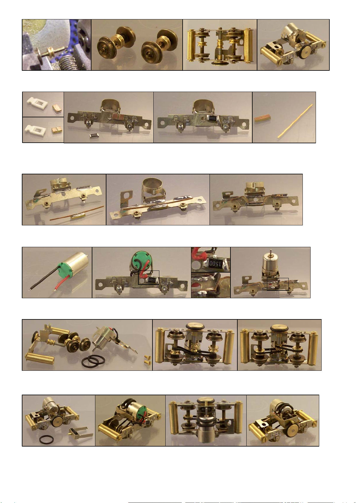
Identify the insulated wheel on each wheel set R; this has a black plastic bush behind the wheel. Carefully remove the insulated wheel on
each wheel set. Use a press action if possible to prevent any distortion of the plastic insulator, otherwise support on a vice with pliers and
gently drift out the axle using a 1mm-1.5mm punch or broken drill shank (shown in photo). If drifting take care to to burr over the end of the
shaft, of you do remove burring with a toolmakers’ stone. Fit one of the 3mm root 4mm OD pulleys S on to the shaft of each wheel set (press
on or open out and fix with thread lock). Take care not to bend the wheel set’s shaft. Position the pulleys to align with the 1.7mm root pulleys
on the lay shaft when assembled into the chassis. This should place the side of one pulley around 3mm from the non-insulated wheel and the
other around 4.7mm from the non-insulated wheel.
It is important that the shaft can rotate freely, to test this temporarily assemble the frames with the two 3.5mm OD x 12.5mm x 12BA brass
spacer C and c/s 12BA screws D, fit the shaft and flick the friction wheel and see that in runs on for a couple of turns before stopping. .
Remove one of the washers A6 from the fret and fit to the shaft above the pulley. Cut the shaft adapter to half length. Feed the shaft though
A1and fit the cut down shaft adapter O with the non-sawn i.e. smooth edge to the frame side. Fix the shaft adapter in place on the shaft with
thread lock so that the shaft rotates freely but has minimal side to side movement, use the built-in feeler gauge below fret A titles between the
pulley/washer and chassis side. Dismantle the frames & spacers.
Fit the two 1.7mm root 2.7mm OD pulleys P to the shaft and position as shown with the first pulley about 0.5mm from the folded part of the
mechanism side frame. Re-attach one spacer to each end of A1 with two of the 12BA screws. Fit the shaft through the hole in A2 and attach
A2 to the two spacers with the remaining two 12BA screws. Fit the 7mm OD 1mm cross section O ring M on to the 5mm root pulley. Check
the lay shaft with its pulleys and friction wheel can rotate freely and runs on for at least one turn after being flicked.
4
The chassis is now ready for final assembly. Fit the wheel sets’ non-insulated side external shaft extensions into the bearings on the
mechanism side frame A1. Loosely fit two of the 6.5mm ID drive belts T over the 1.5mm shaft and around the shaft of each wheel set. Offer
up the mechanism side frame with wheel sets etc to the pickup side frame, fit wheel sets to bearings and 1.5mm shaft to the corresponding
holes and attach the pickup side frame to the spacers using the 12BA c/s screws D. Stretch the belts over the pulleys.
Dismantle the two halves of the chassis by removing the screws on the side to which the motor is mounted. Locate the surface mount resistor
and 0.8mm PCB mounting pad H. Trim the pad to 4mm x 2mm using a flat needle file and make a gap in the copper layer using a round
needle file. Attach the PCB mounting pad to the outside of the pickup side frame A2 using metal epoxy. When set solder the chip resistor
across the gap and short (connect) the right hand side of the resistor to the chassis metalwork with solder. Locate the 0.8mm PCB material U
and phosphor-bronze strip V. Trim the PCB to 1.5mm wide and around 4mm long.
Adjust the pickups and trim to avoid shorts to the frame if necessary. Fit the swinging arm between the motor and large friction wheel and fit
one of the 6.5mm ID drive belts T between the two hooks over the top of the motor. Test run the chassis with direct connections to the wheels
(I use a wheel cleaning brush for this) and check the reduction system works, adjust the motor’s pressure on to the friction reduction by curling
or un-curling the larger hook if necessary. Check for clearance between the swinging arm and 6mm friction wheel and adjust if necessary.
Email me at [email protected] if you have difficulties getting your chassis working, and if you cannot get it going I am always
prepared to get it working for you for a further charge.
Re-fit the insulated wheel on each wheel set using a lathe to hold the two parts in the correct alignment if possible (shown in photo), otherwise
using a press or with great care using a vice. Beware of damaging the 0.8mm diameter external shaft extensions. Also take care not to bend
the shafts of the wheel sets when pressing etc.
Solder the phosphor bronze strip to the PCB using 240C (standard) solder. Using 240C solder to attach the phosphor-bronze allows the
contact wire to be connected using 140C solder without the phosphor-bronze falling off! Mount the PCB to the inside of the pickup side frame
using metal epoxy. When set form the shape of the pickups and cut the phosphor bronze strip to length.
Cut the black motor wire to 15mm long and strip the insulation from the end 1mm. Tin with 140C solder and connect the motor to the pickup
PCB. Cut the red motor wire to 9mm long and strip the insulation from the end 1mm. Tin with 140C solder and connect to one side of the
resistor PCB pad, not to the top of the resistor as this would short to the body when the body is fitted to the chassis.
5
Body
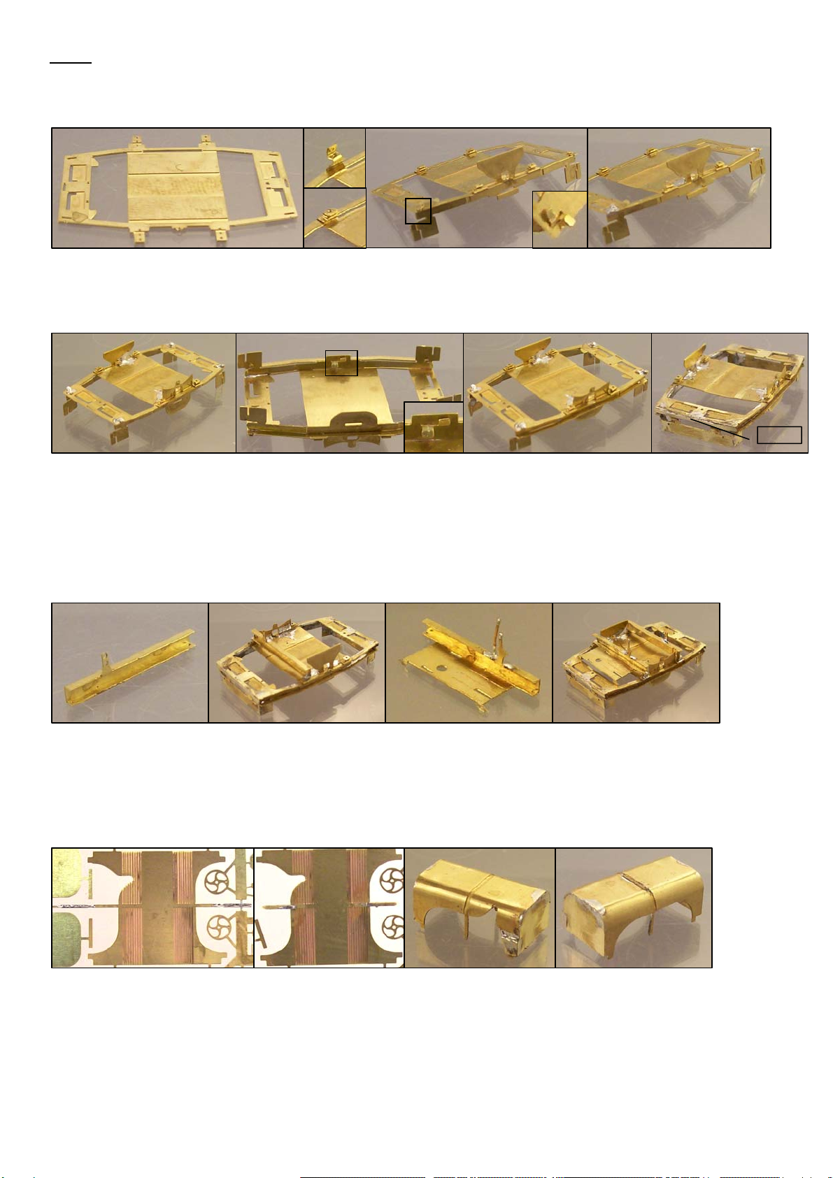
Remove the upper frames B1 from the B fret. Fold the triple fold brackets and the small tab with a hole (starting handle hole) on the upper frames
B1 noting that the half etched lines are on the outside of these folds. Clear the slots in B1 with the end of a sharp scalpel or small hobby knife.
Remove the side frame engine side B2 from the B fret. Fit the engine detail and tabs of B2 through the slots in B1 checking that the orientation of
both parts is correct. Fold over the tabs to hold in place, one half in each direction for the split tabs (these are sacrificial and will be removed
later). Make sure there is no gap between the parts before soldering and that all tabs are correctly engaged in their slots. Apply flux and tack in
place with a very small amount of solder in the area of each tab ensuring that the two parts are at right angles to each other.
Identify the bonnet/hood top and sides B6. Tin the bonnet strap strengtheners, which project above and below, then carefully cut the only the
traces connecting the strengtheners to the fret. Fold the bonnet strap strengtheners back towards the centre of the piece on the side with
multiple half etched lines and solder in place. Remove the sacrificial bend areas. Remove the bonnet/hood top and sides B6 from the fret. Tin
the back of both of the bonnet hinge overlays B34 whilst still in the fret Remove the end pieces B7 from the fret taking care not to lose the
hinge overlays B34. Curve the sections of B6 with multiple fold lines using round nosed pliers to match the shape of the ends B7 which fit
inside B6. Fit the ends B7 and solder with the bonnet standing vertically on a heat-resistant surface to ensure the ends are flush. Ensure the
gaps between the top/sides and ends in the curved section are filled with solder. Tin one of the bonnet power bulge parts B11 on the opposite
side to the half etched fold line. Remove from the fret, fold back on itself and solder. Fit the double thickness power bulge to the
bonnets/hood in the position shown. Fix one bonnet hinge overlay to the top of the bonnets/hoods. Reflow the tinning solder to fix or use
metal epoxy. Set the bonnets aside for later assembly.
Remove the cross member (radiator end) B8 from the fret and fold up to a U shape with the half etched fold lines on the inside of the folds. A
folding jig is good for this part if you have one. Fold the small bracket with the fold line on the inside and secure with solder. Remove the cross
member & driver platform B5 from the fret and fold the U shape at one end. Note that not all the half etched lines on this unit are fold lines!
Fold back the control levers and reinforce all folds with solder. Fold the two half etched triangular pieces flush with the edge of the platform.
Open up if the hole in each of the four triple fold brackets on the upper frame with a 0.4mm drill. Cut four 2mm lengths of 0.4mm diameter wire
and fit one in each hole. Offer up the cross member (radiator end) and check for alignment of the holes in the cross members with the wire
pins in the frame. Adjust either or both assemblies as necessary and solder in place, cutting off excess wire. Repeat for the cross member &
driver platform. Note that the folded down triangular brackets sit inside and on top of the upper frame. Do not solder this end of the platform
yet.
The majority of the construction of the body should be carried out with a sacrificial strengthener in place between the upper frames (B1). This
protects the shape of the frames from distortion during handling; please do not remove the strengthener before the stage indicated in the
instructions. Various sacrificial tabs also included in the side and lower frames. These should be removed when indicated in the instructions.
The main strengthener which is part of B1 is the last one to be removed. Note that not all half etched lines in this kit are fold lines, check first!
Radiator
End Seat
End
Sacrificial
Strengthener
Remove the side frame gearbox side B3 from the fret and fit the gearbox detail fitting the tabs of B3 through the slots in B1 and fold over the
tabs to hold in place, one half in each direction for the split tabs. Tack in place ensuring the parts are at right angles to each other. Remove
two of the lower frames B4 from the fret and fit one to each side frame fitting the tabs of B4 through the slots in B2 & B3. Fold over the tabs to
hold temporarily (these are again sacrificial) and tack in place. Remove the end frames B9 from the fret and fit between the two side frames
but do not solder at this stage. Carefully check the joints and alignment of the frame parts, remove the end pieces and solder the frame sides
along all joints, take care not to apply any solder inside the U channels as an overlay will be added here. Remove the sacrificial tabs by
bending and/or grind back with a slitting disc or diamond disc in a mini drill. Pay particular attention to the tabs inside the ends of the frame as
it will be difficult to access these once the end pieces are fitted. Re-fit the end frames, solder in place and remove the sacrificial tabs. Apply a
small amount of flux to and tin the back of two of the frame end pieces B10 whilst still on the fret. Remove two frame end pieces B10 from the
fret. File the end flat underneath the overhang of the top frame. Apply a small amount of flux under the overhang of each end frame in turn,
position one of the frame end pieces centrally and re-flow into place.
B10

6
If soldering first tin then remove the engine overlay B19 from the fret and fix to the engine side frame using solder or metal epoxy lining up
the lower hole with the starting handle hole. If soldering first tin then remove one of each of the gearbox overlays B20 & B21 and fit to the
gearbox side frame using solder or metal epoxy.
If soldering first tin the rear centre part of four of the sand boxes B29 then remove from the fret and fold up the sides if soldering leaving the
top open to allow access to re-flow the base. Position in the half etched areas at each end of the frame and fix by reflowing the tinning
solder or using metal epoxy. If soldering fold down the tops. Some filing of the sides may be needed especially around the top fold. This is
most easily done in pairs when soldered to the frame but before the tops are closed down.
Using a mini drill and cutting disc cut through the half etched area in the centre of the frames and bend the two resulting tabs repeatedly until
the break at the inside of the frame. Remove any other remaining sacrificial tabs, noting that the tab under the frame on the engine side is
sacrificial. Grind off any protruding solder and clean up. Test fit the chassis to the body checking for any fouling. Solder the completed
bonnets to the two cross members located by the half etched sections on both parts.
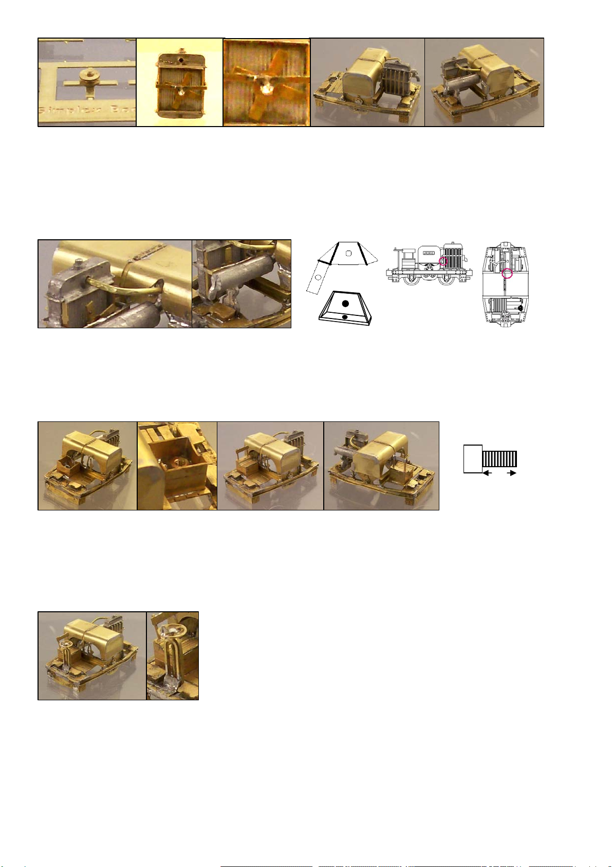
Locate the radiator whitemetal casting X. Open up the hole for the upper hose and check that the 0.6mm wire can be introduced. Open up
the smaller holes in the base and check the 0.4mm wire can be introduced. If soldering the radiator detail parts tin two of the radiator flanges
B23 with a very small amount of solder whilst still on the fret. Remove one of the radiator flanges B23 from the fret and fit to the upper end of
the radiator casting, you may find it easier to put in on from the lower end. If soldering tin both sides of one of the fan boxes B26 except for
in the half etched lines. Fold into a square and test fit to the rear of the radiator casting. This part fits snugly between the two flanges.
Check for position and solder to the upper flange with low melt solder. If soldering first tin one of the radiator bars B22 where shown.
Remove one of the radiator bars B22 from the fret. Carefully fold and fit around the radiator joining to itself at the rear. Remove a second
radiator flange B23 from the fret and fit to the lower end of the radiator. Bend the half etched lines and join the bars to the flanges adjusting
their position as necessary then join the flanges and bars to the radiator casting using low melt solder or metal epoxy very sparingly. Run a
0.4mm drill through the hole at the back of the radiator bars part and make a corresponding hole 1mm or so deep in the casting. This is the
fan pivot.
Identify the end, side & frame overlays B12, B13, B14, B15, B16, B17, B18 on the fret. If soldering these detail parts tin the rear of these
(2 x B13, 1 x B14, 1 x B15, 2 x B16, 2 x B17, 2 x B18). Fit to the appropriate areas of the frame using solder or metal epoxy. Take care
to fit the correct overlay particularly with B16 and B17, note the three larger bolt heads are positioned inboard (see line drawing). Identify
the frame overlays B18 and if soldering tin the back of two of these whilst still in the fret. Remove from the fret and trial fit inside the U
channel section of one side of the frame. Scrape away any solder and/or glue within the U section that gets in the way. Once the fit is
good apply flux to the frame and fix the overlay in place by re-flowing the tinning solder or using metal epoxy.
7
Cut a 15mm length of 0.6mm wire and form into the shape required for the upper radiator hose using the 1:1 plan view on the box liner.
Trial fit between the underside of the bonnets and the hole at the top of the radiator and adjust and trim as needed. Bend the bonnets end
of the wire so that the end is against the inside of the top of the bonnets close to the entry point checking that the entry point through the
side is correct. Glue the radiator end of the hose wire with metal epoxy and tack the bonnets end in place with solder or fix with metal
epoxy. Locate the exhaust whitemetal casting W. If you decide to build the version with the etched exhaust support cut away the cast-in
support on the exhaust, then remove the exhaust bracket B39 from the fret, fold into shape and fix to the frame. Trial fit the exhaust
casting to the frame or bracket and bonnets bending & trimming the bonnet end to bring into contact with the inside top of the bonnets
adjacent to the wire radiator hose such that the exhaust is level and parallel with the centre line of the loco. Fix in place with superglue or
metal epoxy. Trial fit the chassis to the body and check fo
r
fouling. Grind away any problem areas with a cutting disc or burr in a mini drill.
Remove the seat base B29 from the fret and fold into a square. Test fit to the driver’s platform and adjust if necessary then solder the joining
corner. Fit the seat base to the platform and secure with solder or metal epoxy. Mount the 12BA nut F over the hole in the driver’s platform
within the seat. Solder in place taking care not to get any solder on the threads. Take the 12BA cheesehead screw E and cut it so that there
is 2mm of threads below the head. Check that it will screw into the nut from the underside of the body. Remove one of the seat tops B31
from the fret and fold into shape to fit the base. Remove one of the seat backs B30 from the fret including the rectangular strengthening
piece. Fold the seat back double with the half etched fold line on the outside of the bend. Take great care this is a very delicate part, try
again if you break the first one. Solder the back in place in its supports, remove the strengthening piece and fix the supports to the seat top
using solder or metal epoxy. Fill the seat cavity with liquid lead DD securing in place using metal epoxy taking care not to get any on the
threads of the nut. Block the open end of the nut with blue tack or modelling putty if in doubt about this.
Remove one of the brake columns B32 from the fret. Carefully fold the angles and curve the area around the hole to form the shape of the
brake column. Fold the bracket at the base with the horizontal half etched fold line on the outside of the fold. Take great care this is a very
delicate part, try again with the spare if you break the first one. Mount the brake column and bracket on the centre overlay at the driver’s
end of the frame and fix in place with solder or metal epoxy. The peferred way to attach the brake column is to solder it from below and grind
off the excess solder, bear in mind the stress this part sees when fitting the driver and in general handling. Remove one of the brake wheels
B33 from the fret. Cut an 8mm length of 0.4mm wire and feed through the hole in the centre of the brake wheel fixing with solder. Cut a 1mm
length of 0.4mm wire and fit through the hole on the outer edge of the brake wheel. Fix in place with solder or metal epoxy. Fit the longer
length of wire through the hole in the top of the brake column and position the brake wheel trimming the wire if necessary. Fix in place with a
small amount of solder or metal e
p
ox
y
.
Position the 2.5mm pulley W on top of one of the fans B27. Carefully centralise the two items and fix the fan to the pulley with solder or
metal epoxy glue. Make sure a piece of 0.4mm wire can be put through the centre of fan and pulley and open out with a 0.4mm drill if not.
Position the fan & pulley inside the fan box on the rear of the radiator with the radiator in a horizontal position and the pulley away from the
casting. Feed an approximately 5mm length of 0.4mm wire through the bars, pulley/fan and into the hole in the radiator casting. Fix in place
on the outside with solder or metal epoxy. Fit a short length of 0.4mm wire into the hole in the base of the radiator. Remove one of the
radiator bracket 1 pieces B24 from the fret and fold into shape. Glue or solder to the base of the radiator casting locating with the 0.4mm
wire so that the wire projects around 0.5mm. Remove one of the radiator bracket 2 pieces B25 from the fret and fold into shape. File and
adjust as necessary and solder to hold the shape. Glue or solder to the top edge of the radiator end cross member referring to the plan
views for location and solder or glue in place. Offer up the radiator assembly to the frame locating the 0.4mm wire in the base to the hole in
the end overlay. Check for level and straightness from top, front and side and fix in place with metal epoxy. If you are a true ‘fan’-atic you
can model the belt around the pulley with a length of 0.4mm wire. Go straight on to fit the top hose which stabilises the radiator.
2mm
B25
B25
Position

8
Solder or glue a coupler Z centrally on the ends of the frame. Tack the front then solder or glue the back of the coupling from the inside of
the frame for a strong joint. Remove one of the hose straps B40 from the fret and form one end around a spare piece of 0.6mm wire or a
0.6mm drill shank. Form the shape of the strap and position over the upper radiator hose. Adjust position and shape, bending the lower
end into a U between the chassis and body frames, and fix to the hose and inside of the body frame using solder or metal epoxy.
Tin the back of one of the clutch pedal tops B36 whilst still on the fret. Remove one of the clutch pedal tops B36 fit back to back on one of
the clutch pedal backs B37 whilst still in the fret. Remove the combined clutch pedal from the fret and fit in the slot on the driver’s platform
securing with solder or metal epoxy. The pedal should project 3.7mm above the driver platform.
Note: You may wish to fit the number plates after painting the remainder of the loco.
Remove two of the number plates B38 from the fret and position on each side of the bonnet/hood. If fitting before painting you can tin
these and fix them by re-flowing the solder as for other detail parts, or use metal epoxy before or after painting.
Fit the chassis to the body and secure with the 12BA screw through the hole in the chassis tab into the nut in the seat base.
Painting – the locos were originally painted in an olive drab colour, I suggest using Humbrol Slate Grey No 31 to represent a somewhat
faded dirty and weathered state (thanks to Pete Wilson for this advice). The visible parts of the mechanism including the motor and its
support, 3mm root pulleys and much of the chassis etchings should also be painted, I suggest matt black for the areas which are not part
of the model including the parts of the functional chassis frames which ‘should not be there’. This will help them sink into the background.
The numbers on the number plate should be white, a white gel pen or white paint with extremely small brush can be used for this
(magnifying glass recommended). The exhaust seems to be dark grey in most modern locos, I expect this or a rusty appearance is the
closest to reality. Details of the driver’s uniform should be researched in detail by the individual modeller, but it would be mainly a khaki
colour.
LR2832 LR2832
Remove two of the spring buffers B35 from the frets and bend to shape. Open up the two small holes with a 0.4mm drill. Cut two 2mm
lengths of 0.4mm wire and fit one to each of the holes in one end piece. Fit the bent buffer and fix in place with solder or metal epoxy.
Repeat for the other end piece and spring buffer.
Table of contents


