Nissindo MA-1330 POWER User manual
ON
POW E R
OF F Professional power amplifier MA-1200 G2
B R I D G E
P E A K
S I G N A L
CH - 2
0
-2
-4
-6
-8
-10
-12
-14
-16
-18
-20
-24
CH -1
0
-2
-4
-6
-8
-10
-12
-14
-16
-18
-20
-24
ON
POW E R
OF F Professional power amplifier MA-1200 G2
B R I D G E
P E A K
S I G N A L
CH - 2
0
-2
-4
-6
-8
-10
-12
-14
-16
-18
-20
-24
CH -1
0
-2
-4
-6
-8
-10
-12
-14
-16
-18
-20
-24
w w w . N i s s i n d o U S A . c o m
Professional Power Amplifier
MA-1200 G2 POWER 1000W
MA-1 33 0 POWER 2000W
MA-2000 POWER 3200W
OPERATING INSTRUCTIONS
MANUAL

2
Safety
Applications
Features
Intro
Amplifier
CONTENTS
INTRODUCTION....................................................................................................................................... 3
SYSTEM FEATURES...............................................................................................................................3~5
SAFETY INSTRUCTIONS......................................................................................................................6~7
SYSTEM CONNECTIONS.................................................................................................................... 8~9
• Connecting the Power Amplifier to Mixer.......................................................................... 10
• Connecting the Power Amplifier to Speaker...................................................................... 10
• Small Format/Medium Format/Large Format...................................................................... 11
• Center Vocal Monitor Connection with 5-D Pro Audio........................................................12
• Power Amplifiers Operating for Different Formats................................................................ 12
CONTROLS AND FUNCTIONS.............................................................................................................13
• Front Panel............................................................................................................................13
• Rear Panel.............................................................................................................................13
FUNCTION SET UP.................................................................................................................................14
PHYSICAL DIMENSIONS.......................................................................................................................15
SPECIFICATIONS.................................................................................................................................... 16
WARRANTY............................................................................................................................................ 17
AGENCY REGULATORY NOTICES..............................................................................................................18
FINAL WORDS TO USER.......................................................................................................................19
CONTACT INFORMATION...........................................................................................................................19
Spec
Dimensions
Warranty
Final Words
Notices
Contact Us
Set Up

Professional power amplifier MA-1 200 G2
BR I D G E
P E A K
SI G N A L
ON
POW ER
OFF
CH-1
0
-2
-4
-6
-8
-10
-12
-14
-16
-18
-20
-24
CH- 2
0
-2
-4
-6
-8
-10
-12
-14
-16
-18
-20
-24
3
Intro
INTRODUCTION
Nissindo is proud to introduce a high power amplifier MA
Series to the North America market. They are designed by
the Nissindo engineering team with the advanced audio
technology. One of the distinguished features of this new
amplifier series is that they produce crystal clear vocal sound
and music for singing as compared to other brands in the
market.
If you want a high-performing, precise clarity, low
temperature, reliable, and portable power amplifier, you may
look into our MA Series. Coming in three models, the
MA-1200 G2 (1,000 watts), MA-1330 (2,000 watts) and
MA-2000 (3,200 watts), the MA Series power amplifiers
give you high power (which is as high as 3,200 watts),
compact size 2-space, and efficiency for your application.
They feature Nissindo’s latest Auto Temperature and Loads
Compensated Impedance and Supply Control Technology™
circuitry for clean, undistorted sound with the ultimate circuit
protection needed by amps which often get pushed to the
limit.
The Nissindo engineering team has brought the power and
portability of high power amplifier into the consumer market.
The compact 2U design of the KTV can easily be mounted
onto the versatility of the compact DJ rack system or any
Karaoke Rental Gear; allowing many restaurants and bars
venue to have sound quality on rack or on the go for
maximum power and portability.
To expand into high power (as high as 3,200 watts), the
MA series would go with either a pre-amplifier or a mixer. A
normal mixing amplifier can produce the power from 200
watts to 800 watts only.
The Nissindo MA Series has elevates the audience’s
experience by combining the power of professional precision
crossovers and acoustic correction for high definition clarity
and performance. While the MA Series can thrust a huge
amount of bass that the audiences can literally feels the
pressures, it does not create the "muddy" overall sound like
other systems, even for those directly in front of the speaker.
Instead, it delivers the vocal and music in a very precise,
focused, high-definition quality sound to its very limits,
providing clearer, and more accurate sound to the entire
audience; even when used in highly reverberant huge area
like churches and banquet halls.
Features
SYSTEM FEATURES
MA Series is equipped with the following
distinguished features:
Models: MA-1200 G2 (Generation 2)
MA-1 3 30
MA-2000
• Housed in a rugged, all-steel 2U chassis
• Rear panel selection switch for Stereo, Parallel and Bridged
modes, including Low-cut filter, Ground lift and Limiter
switches
• Operates within 8 ohms and 4 ohms loads
• Innovative heatsink with front to back air flow for efficient
cooling
• Variable fan speed is automatically adjusted by
temperature
• Electronically balanced XLR inputs
• Touch proof binding post and Speakon outputs
• Precision indented level controls, power switch
• Bridge, Peak and Signal LEDs indicators for each channel
• Amplifier protection includes short circuit, excessive
temperature, and DC on outputs
SPECIAL FEATURE DESCRIPTIONS
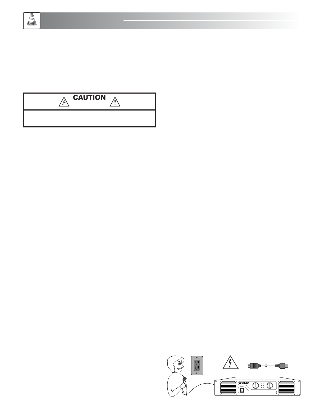
AC-POWER SWITCH
Before applying power, check all connections and turn
down the gain controls. The "soft start" sequence starts with
the POWER indicator LED at half brightness. A couple
seconds later the fan starts and the amplifier cycles through
one second of protective muting, indicated by the CLIP LEDs
glowing bright red. The POWER indicator then changes to
full brightness and the amplifier is ready.
The power cord has a big beefy cord built in. Plug the
power cord into a 3-prong outlet that is capable of
delivering 110~120V at 15 amps.
ON
POWER
OFF
INPUT
PIN1:SIGNAL GND
PIN2: SIGNA L +
PIN3: SIGNA L –
BRIDGE
PARALLEL
STEREO
50HZ
25HZ
5HZ
OFF
ON
OFF
ON
CH-1 BRID GE IN
CH-2 BRID GE IN
SERIALNO.:
CAUTION
RISKO F ELECTRI C SHOCK
DONOT O PEN
BRIDGE
CH-1OUTPUT
POWERCABLE
FUSE
CH-2OUTPUT
-
+
CH-1
+
-
+
-
CH-2
SAFETY
MARK
USA020898-11
020898-11
ITEMNO.D030905
CALIFORNIA,UNITED STATES OFAMERICA
E-mail:[email protected]
www.NISSINDOUSA.com
ENGINEERED AN D DESIGN I N U.S.A.
MODE LFFILTER CLIPLIMITER GROUND
4
LED INDICATORS
The LED indicators can be used to monitor system operation
and identify common problems.
BRIDGE: Each channel pair has a YELLOW LED for BRIDGE
Mode. These show how the rear panel switches are set. In
Stereo mode, both LEDs should be OFF.
PEAK: RED, under each BRIDGE LED. Each channel pair has
a RED LED for PEAK Mode.
Normal indication:
The PEAK indicator illuminates whenever the amplifier is
driven beyond full power. The resulting distortion corresponds
to the brightness of the LED. Distortion that causes only brief
flashing may not be audible.
• During muting, the LED fully illuminates. This occurs during
normal "On-Off" muting.
Abnormal indication:
• Bright RED illumination while the amp is being used
indicates either thermal muting or a shorted output.
• If the amplifier overheats, the fan will run at full speed,
and operation should resume within one minute. Allow the
fan to run, and make sure the amplifier ventilation is
adequate.
• A shorted or overloaded output circuit will cause excessive
PEAK flashing and possible overheating.
If distortion is audible without a PEAK indication, the problem
is either before or after the amplifier. Check for damaged
speakers or overloaded signal source. The amplifier Gain
control should be in the upper half of its range to prevent
input overload.
SIGNAL: GREEN, under each PEAK LED. Each channel pair
has a GREEN LED for SIGNAL Mode.
Normal indication:
The SIGNAL indicator illuminates when the input SIGNAL
exceeds -35 dB, the -20dB indicator illuminates when the
signal exceeds -20dB, and the -10dB indicator illuminates
when the signal exceeds -10dB.
If no indication:
check Gain settings and increase gain if necessary. Check
input connections and audio source for signal. If the SINGAL
LED illuminates with little or no signal indication, check the
output wiring for shorts.
Abnormal indication:
If the SIGNAL, -20dB, or -10dB LED illuminates with no signal
input, there may be system oscillations or some other
malfunction. Disconnect the load and fully reduce the gain. If
the LED remains on, the amp may need servicing.
BRIDGE MONO MODE
What It Is
BRIDGE mono mode combines the power of both amp
channels into one speaker, resulting in twice the voltage
swing, four times the peak power, and approximately three
times the sustained power of a single channel. This mode uses
Channel 1's input, gain control, input filter, and PEAK limiter;
Channel 2's have no effect.
The BRIDGE LED on the front panel indicates when the amp is
in BRIDGE mono mode.
When To Use It (or Not)
Use BRIDGE mono to deliver the power of both channels to a
single 8 or 4 ohms load. Set switch position 7 to "BRIDGE
MONO ON." Use Channel 1's inputs, and connect the
speaker as shown.
Bridge-mono Precautions:
This mode puts a high demand on the amplifier and speaker,
Excessive clipping may cause protective muting or speaker
damage. Be sure the speaker has a sufficient power rating.
Output voltages greater than 100 volts rms are available
between the amplifier's BRIDGE terminals. NEC CLASS 3
wiring methods, as specified in accordance with national and
local codes, must be used to connect the speaker.
BRIDGE
PARALLEL
STEREO
50HZ
25HZ
5HZ
OFF
ON
OFF
ON
MODE LF FILTER CLIPLIMITER GROUND
UPPER SPEAKON ONLY TO SPEAKER
REFERENCE CONNECT
2–
1+ 2+
16
8
4
+
-
1–
5
PARALLEL INPUT MODE
What It Is
The "Parallel Input" switches let you operate the amplifier in
parallel mode, delivering the same SIGNAL to both channels
without using a Y-cable. Each channel drivers its own speaker
load, with independent gain, filtering, and clip limiting.
Set switch positions 4, 5, and 6 "ON" to couple the inputs
together. Turn the switches off for stereo, bridge, or other
2-channel modes.
With the inputs in parallel, you can use the other set of input
connectors to carry the SIGNAL to other amps. This is often
called a "daisy-chain."
When To Use It
Parallel the inputs when driving two speakers with one input
SIGNAL (parallel mode) while keeping separate control of
both channels' gain, filtering, and limiting. Use them in
BRIDGE mono mode to patch the SIGNAL to additional
amplifiers through the extra input jacks.
If you are using a balanced SIGNAL, use only
balanced patch cables; even one unbalanced cable will
unbalance the entire SIGNAL chain, possibly causing hum.
Turn off the "parallel Inputs" switches when feeding the amp
two separate SIGNALs.
WHAT ARE THE DIFFERENCES AMONG STEREO,
PARALLEL INPUT, AND BRIDGE MONO MODES?
Stereo Mode
This is the "normal" way of using the amplifier, in which each
channel is fully independent. Separate SIGNALs connect at
the inputs, the gain knobs control their respective channels,
and separate speakers connect to each output.
Examples:
• Two-channel (stereo) playback.
• Two independent mono SIGNALs, such as main and
monitor mixes.
• Bridge operation, with the low frequencies in Channel 1
and the highs in Channel 2.
Parallel Input Mode
This mode is just like Stereo mode, except that the inputs for
Channel 1 and Channel 2 are internally connected together.
A SIGNAL into any input jack will therefore drive both
channels directly. Each channel’s gain control still functions as
usual, and each channel feeds its own speaker load.
You can patch the input SIGNAL on to additional amplifiers
by using any of the remaining input jacks.
Example:
• One mono SIGNAL driving both channels, with
independent gain control each speaker system.
Bridge Mono Mode
This mode combines the full power capabilities of both
channels into a single speaker system. The amplifier internally
re-configures so that both channels operate as a unit. This
delivers double the output voltage, resulting in four times the
peak power and three times the sustained power into a single
8 or 4 ohms speaker load.
Example:
• Driving a single 8-ohm speaker with the combined 4-ohm
power of both channels.
• Driving a single 4-ohm speaker with the combined 2-ohm
power of both channels.
Precautions:
• BRIDGE Mono mode makes it possible to drive thousands
of watts into a single speaker. AC current consumption will
usually be higher. Avoid excessive SIGNAL level, and make
sure the wiring and speaker can handle the power.
• If the load is less than 4 ohms, or prolonged overloads
occur, the amplifier will probably mute for several seconds
during peaks.
• Do not use 2 ohms loads.
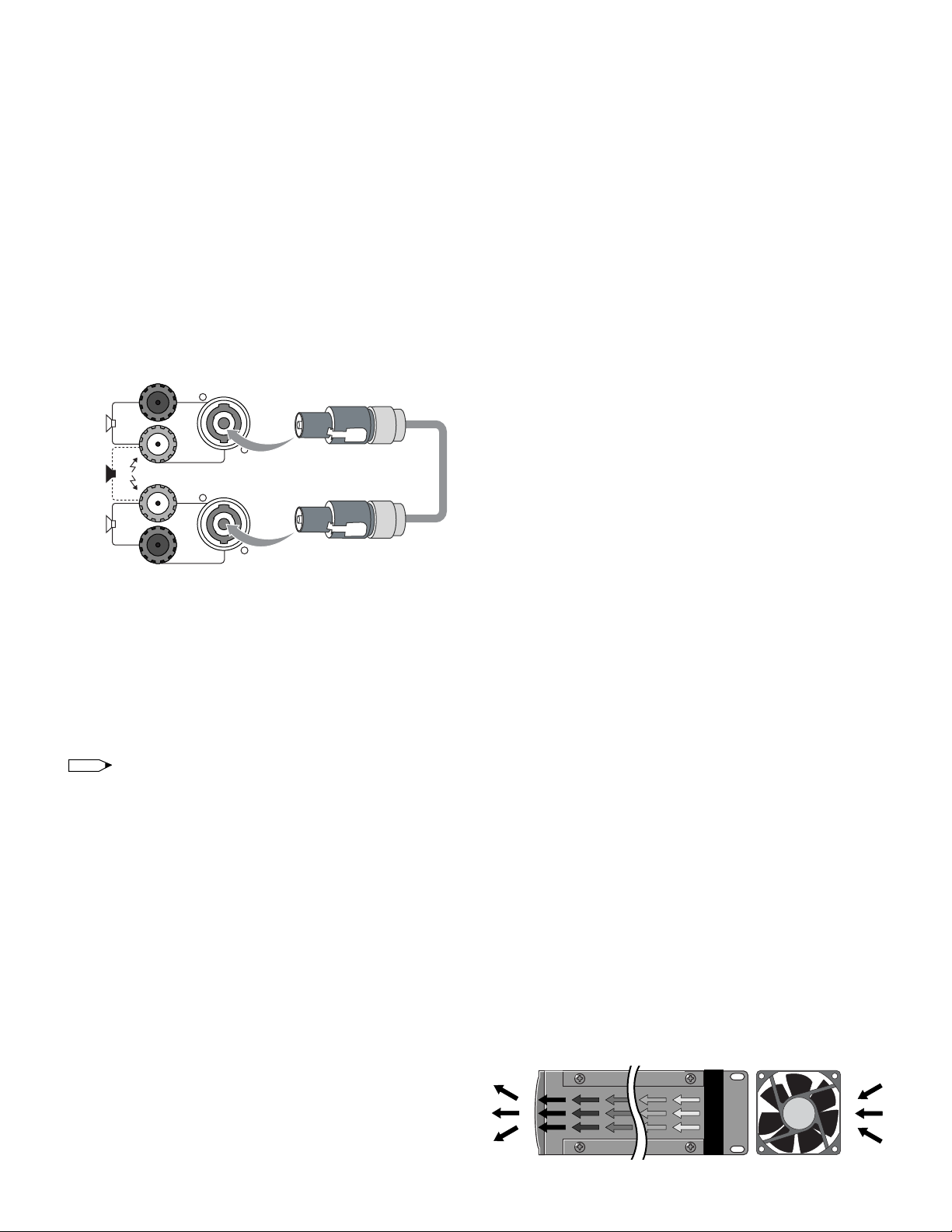
FAN COOLING
The fan speed varies automatically to maintain safe internal
temperatures. Keep the front and rear cents clear to allow full
air flow. Hot air exhausts out the front of the amp so it does
not heat the interior of the rack. Make sure that plenty of cool
air can enter the rack, especially if there are other units which
exhaust hot air into it.
BRIDGE
CH-1 OUTPUT
CH-2 OUTPUT
-
+
CH-1
+
-
+
-
CH-2
NOTE
AMPLIFIER SIDE VIEW
Fan
WARM AIR EXISTS COOL AIR ENTERS
6
RISK OF ELECTRIC SHOCK
DO NOT OPEN
CAUTION: TO REDUCE THE RISK OF ELECTRIC SHOCK DO NOT
REMOVE COVER (OR BACK) NO USER-SERVICEABLE PARTS
INSIDE REFER SERVICING TO QUALIFIED PERSONNEL
Safety
AC-POWER CORD INCLUDED120V AC-POWER
Safety
SAFETY INSTRUCTIONS
We will not notify you any errors or changes in this manual in
advance. If there are any errors and changes in this manual,
we will make the corrections in a timely manner. The
corrections and changes will be appeared in our website.
Therefore, please visit our website at www.NissindoUSA.com
frequently to find out the most updated information,
corrections on errors and changes in this manual. You may
also contact us at toll free at 1-800-318-2218.
1. Read Instructions: All the safety and operation instructions
should be read before this product is operated.
2. Retain Instructions: The safety and operating instructions
should be kept for future reference.
3. Warnings: All warnings on this product in these operating
instructions should be followed.
4. Follow Instructions: All operating and other instructions
should be followed carefully.
5. Water and Moisture: This product should not be used near
water, for example, near a bathtub, washbowl, kitchen sink,
laundry tub, in a wet basement, near a swimming pool,
swamp or salivating St. Bernard dog, etc.
6. Cleaning: Clean only with a dry cloth.
7. Ventilation: This product should be situated so that its
location or position does not interfere with its proper
ventilation. For example, the Component should not be
placed on a bed, sofa, rug, or similar surface that may block
any ventilation openings, or placed in a built-in installation
such as a bookcase or cabinet that may impede the flow of
air through ventilation openings.
8. Heat: This product should be stayed away from heat
sources such as radiators, or other devices producing heat.
9. Power Sources: This product should be connected to a
power supply only of the type described in these operation
instructions or as marked on this product.
10. Power Cord Protection: Power supply cords should be
routed so that they are not likely to be walked upon or
pinched by items placed upon or against them. Please pay
particular attention to cords plugs, convenience receptacles,
and the point where they exit this product.
11. Object and Liquid Entry: Care should be taken so that
objects do not fall on, or liquids are not spilled into this
product.
12. Damage Requiring Service: This product should be
serviced only by qualified service personnel when:
A. The power-supply cord or the plug has been
damaged; or
B. Objects have fallen, or liquid has spilled into this
product; or
C. This product has been exposed to rain; or
D. This product does not appear to operate normally
or exhibits a marked change in performance; or
E. This product has been dropped, or its chassis has
been damaged.
13. Servicing: The user should not attempt to service this
product beyond those means described in this operating
manual. All other servicing should be referred to the Service
Department.
14. To prevent electric shock, do not use this polarized plug
with an extension cord, receptacle or other outlet unless the
blades can be fully inserted to prevent blade exposure.
15. Grounding or Polarization: Precautions should be taken so
that the grounding or polarization means of this product is not
defeated.
16. Power Precaution: Unplug this product during lightning
storms or when unused for long periods of time. Note that this
product is not completely disconnected from the AC power
source when the power switch is in the OFF position.
17. This machine does not exceed the Class A/Class B
(whichever is applicable) limits for radio noise emissions from
digital apparatus as set out in the radio interference
regulations of the US Department of Communications.
AC-POWER SOURCES
This set should be operated only from the type of power
source indicated on the marking label. If you are not sure of
the type of electrical power supplied to your home, consult
your dealer or local power company. For those sets designed
to operate from battery power, or other sources, refer to the
operating instructions.
This unit is designed for use with 120V/60Hz AC. If the area
where you live have different power source, you may need to
use a transformer to convert to 120 Volts AC.
Professional power amplif ier M A-12 00 G2
BR I D G E
P E A K
SI G N A L
ON
POWE R
OFF
CH-1
0
-2
-4
-6
-8
-10
-12
-14
-16
-18
-20
-24
CH-2
0
-2
-4
-6
-8
-10
-12
-14
-16
-18
-20
-24

Professional p ower amplifier M A-1200 G2
BRIDG E
PE A K
SIGNA L
ON
POWER
OFF
CH-1
0
-2
-4
-6
-8
-10
-12
-14
-16
-18
-20
-24
CH-2
0
-2
-4
-6
-8
-10
-12
-14
-16
-18
-20
-24
Professional power amplif ier M A-12 00 G2
BR I D G E
P E A K
SI G N A L
ON
POWE R
OFF
CH-1
0
-2
-4
-6
-8
-10
-12
-14
-16
-18
-20
-24
CH-2
0
-2
-4
-6
-8
-10
-12
-14
-16
-18
-20
-24
7
OVERLOADING
Do not overload wall outlets, extension cords or convenience
receptacles beyond their capacity, since this can result in fire
or electric shock.
An appliance and cart combination
should be moved with care. Quick
stops, excessive force and uneven
surfaces may cause the appliance and
cart combination to overturn.
Do not place the electronic equipment onto the unstable
table or stand. It is because it would fall easily from the
unstable table or stand, so it may cause accident including
personal injuries and
damage the equipment.
Please follow our instructions
to install the equipment, or
you may hire a professional
technician to handle the
installation for safety
purpose.
Do not store the electronic equipment near water or area
with moisture such as bathroom, kitchen sink, laundry area
and swimming pool, etc.
Do not place the electronic equipment near heat sources
such as stoves, radiators and heaters, etc. Placing the
electronic equipment too near to these heat sources would
result in damaging the equipment and causing fire.
120V AC-POWER
Do not place the set on an unstable cart, stand, tripod,
bracket, or table. The set may fall, causing serious injury to a
child or an adult and serious damage to the set. Use only a
cart stand tripod, bracket, or table recommended by the
manufacturer.
For the set with a three-wire grounding type ac plug:
This plug will only fit into a grounding-type power outlet.
This is a safety feature. If you are unable to insert the plug
into the outlet, contact your electrician to have a suitable
outlet installed. Do not defeat the safety purpose of the
grounding plug.
Do not transport the electronic equipment by yourself if its
weight exceeds 70 pounds. It is recommended that two
people work together to transport the equipment or by using
hand truck and the like.
Do not place the electronic
equipment directly under sunlight
or close to the window. It may
cause overheat on the electronic
equipment by the sunlight.
Do not block the openings and vents in the cabinet which
is designed for the ventilation of the electronic equipment.
The blocking may cause overheat in the electronic equipment
because of insufficient circulation of air, so it would damage
the electronic equipment.
X
HEATER
Professional power amplif ier M A-12 00 G2
BR I D G E
P E A K
SI G N A L
ON
POWE R
OFF
CH-1
0
-2
-4
-6
-8
-10
-12
-14
-16
-18
-20
-24
CH-2
0
-2
-4
-6
-8
-10
-12
-14
-16
-18
-20
-24
Professional power amplif ier M A-12 00 G2
BR I D G E
P E A K
SI G N A L
ON
POWE R
OFF
CH-1
0
-2
-4
-6
-8
-10
-12
-14
-16
-18
-20
-24
CH-2
0
-2
-4
-6
-8
-10
-12
-14
-16
-18
-20
-24
Profession al power amplifi er MA-1200 G2
BRID G E
P E A K
SIGN A L
ON
POWER
OFF
CH-1
0
-2
-4
-6
-8
-10
-12
-14
-16
-18
-20
-24
CH-2
0
-2
-4
-6
-8
-10
-12
-14
-16
-18
-20
-24
POWER ANTENNA-A CNANNEL-ADISPLAY CNANNEL-BDISPLAY
CHANNEL-A
VOLUME ANTENNA-B
CHANNEL-B
VOLUME
DUALCHANNELVHF WIRELESS SYSTEM
RF
AF
FREQ.
5 10 15 20 25 30 35 40
-30 -25 -20 -15 -10 -5 0 PEAK
000.000M
H
Z
MUTE
RF
AF
FREQ.
5 10 15 20 25 30 35 40
-30 -25 -20 -15 -10 -5 0 PEAK
000.000M
H
Z
MUTE
8
OUTPUT INPUT
2+
1+
2–1–
TO
AMPLIFIER
Connector Panel
OUTPUT INPUT
2+
1+
2–1–
TO
AMPLIFIER
FULL
RANGE
BI-AMP
LF
HF
Connector Panel on Multi-Way Systems
OUTPUT INPUT
PASSIVE BI-AMPLING
INPUT PASSIVE OUTPUT
2+ 2+
2– 2–
1+ 1+
1– 1–
SUB
WOOFER
INPUT BI-AMPLING OUTPUT
2+ 2+
2– 2–
1+ 1+
1– 1–
SUB
WOOFER
Connector Panel on Subwoofers
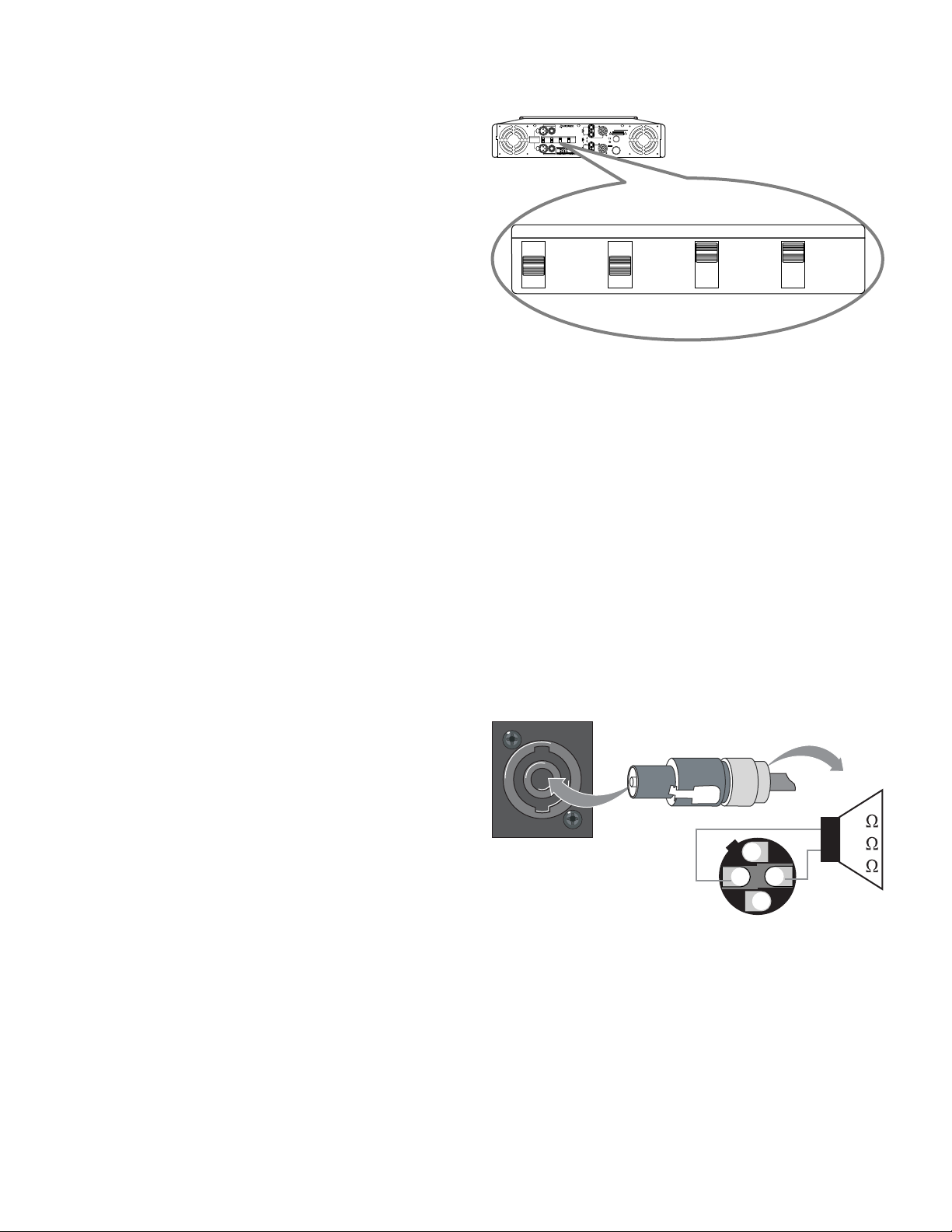
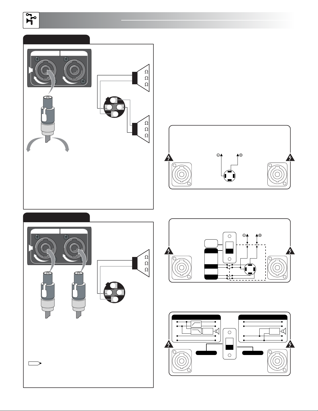
EXAMPLE OF SPEAKON CONNECTOR
There are two groups on the speakon connectors: Group 1
(+1, –1) and Group 2 (+2, –2) as indicated in the diagram. In
order to use it, your speaker must have multi-functions (i.e.
enable two sources of signal for input). If your speaker does
not have multi-functions, it would not work with the Group 2
for connection. Please refer to the following diagram for
connection.
Speakon Outputs
The upper Speakon jack has both Channel 1 and
Channel 2 outputs, so it is especially useful for parallel,
bi-amp, or BRIDGE mono operation. The other Speakon
carries only Channel 2's output. See the illustrations at
above.
SPEAKON Y CONNECTORS
INPUT OUTPUT
L
O
C
K
L
O
C
K
TO CHANNEL 2
SPEAKER
TO CHANNEL 1
SPEAKER
2–
1–
1+ 2+
REFERENCE CONNECT
8
4
2
+
–
8
4
2
–
+
SPEAKON CONNECTORS
INPUT OUTPUT
L
O
C
K
L
O
C
K
SOURCE
(from active/powered)
BRIDGE
2–
1–
1+ 2+
REFERENCE CONNECT
8
4
2
+
–
Source (INPUT) comes from the output source of the
active/powered speaker while the bridge (OUTPUT)
connects to the passive/non-powered speaker.
A speakon cable is required to connect the “OUTPUT”
of the acive/powered speaker to the “INPUT” of the
passive/non--powered speaker. Please order the speakon
cable from our authorized dealers.
NOTE
Applications
SYSTEM APPLICATIONS

9
1SHIELD
COLD
HOT
2
3
1
2
3
SHIELD
COLD
HOT
2
1
3
SHIELD
COLD
HOT
MALE
FEMALE
Balanced XLR Connectors
XLR TRS
Hot (+) Pin 2 Tip
Cold (
-
) Pin 3 Ring
Shield (Ground) Pin 1 Shield
RING (COLD)
TIP (HOT)
SLEEVE (SHIELD)
SLEEVE RINGRING SLEEVE TIP
TIP
Balanced 1/4” TRS Plug
RING (COLD)
TIP (HOT)
SLEEVE (SHIELD)
SLEEVESLEEVE TIP
TIP
Unbalanced 1/4” TRS Plug
RCA Unbalanced Jack
SLEEVE
SLEEVE
TIP
TIP
SLEEVE
SLEEVE
TIP
TIP
R (right)
L (left)
CONNECTOR INFORMATION
Either banana plug or insert type can be used to connect the
unit to speakers. Be sure to connect red (+) to red (+) and
black (–) to black (–). Otherwise, the sound output would be
180° out of phase and distorted.
Follow these steps if you are inserting the wire directly into
the speaker terminal.
1. Strip off the vinyl covering and twist the tip of the
wire core.
2. Loosen the knob and insert the wire core into the
terminal hole.
3. Tighten the knob to fix the wire core in place.
Do not allow the wire core to protrude or touch other
terminals or wires.
If the cores of differing wires touch, damage may result to
your components.
METHODS OF SPEAKER CONNECTION
1. Insert Type (Poor Connection)
2. Single Banana Plug Type (Better Connection)
SPEAKERS
SPEAKERS
NO GOODGOOD
3. Double Banana Plug Type (Standard Connection)
SPEAKERS
3/4”
19 mm
INPUT
PIN1: SIGNALGND
PIN2: SI GNAL +
PIN3: SI GNAL –
BRIDGE
PARALLEL
STEREO
50HZ
25HZ
5HZ
OFF
ON
OFF
ON
CH-1 BR IDGE IN
CH-2 BR IDGE IN
SERIAL N O.:
CAUTION
RISK OF ELEC TRIC SHOC K
DO NOT OPEN
BRIDGE
CH-1 OUTPUT
POWER CABLE
FUSE
CH-2 OUTPUT
-
+
CH-1
+
-
+
-
CH-2
SAFETY
MARK
USA020898-11
020898-11
ITEMNO. D030905
CALIFORNIA,UNITED STATES OF AMERICA
E-mail:[email protected]
www.NISSINDOUSA.com
ENGINEEREDAND DESIGN IN U.S.A.
MODE LF FILTER CLIP LIMITER GROUND
10
INPUT
PIN1:SIGN AL GND
PIN2:SIG NAL +
PIN3:SIG NAL –
BRIDGE
PARALLEL
STEREO
50HZ
25HZ
5HZ
OFF
ON
OFF
ON
CH-1 BRIDG E IN
CH-2 BRID GE IN
MODE L F FILTER CLIPLIMITER GROUN D
SERIALNO.:
WARNING
RISKOFELECTRIC SHOCK
DONOTOPEN
BRIDGE
CH-1OU TPUT
POWER CABLE
AC120V60Hz
4000VA
FUSE
DELAY
T25A/250V
CH-2O UTPUT
-
+
CH-1
+
-
+
-
CH-2
SAFETY
MARK
USA020898-11
020898-11
ITEMNO.D030905
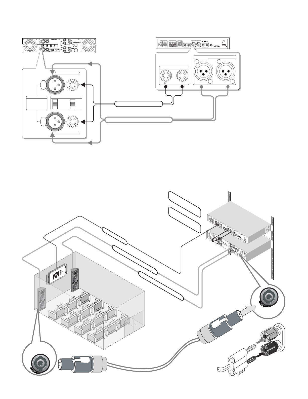
VIDEO MONITOR
MAIN RIGHT SPEAKER WS-6215
MAIN LEFT SPEAKER WS-6215
CPU A/V Effects Processor
REAR VIEW
POWER AMPLIFIER
REAR VIEW
Neutrik Speakon
Connector
CONNECTING THE POWER AMPLIFIER (MA-1200 G2, MA-1330 & MA-2000) TO SPEAKER
OR
Best Speakon Connector
Standard Banana Connector
Neutrik Speakon
Connector
MIXER REAR VIEW
CDGAUX DVD OUT P U T REC
CDGAUX DVD
AUD I O IN P U T TE R M I N A L VI D E O IN P U T TE R M I N A L
REM O T E
INP U T
VID E O M O N I TO R O U T P U T
21 3
MAI N 1
AUD I O (1 / 4) O U T P U T
AUX
INP U T
AC~120V 60Hz 35W
FUSE
AC-POWER
CAUTION
361 20 06 09 08 -1 0
SAFETY
MARK
USA020898-1
020898-1 ITEMNO.D 030906
REA R MI C . IN P U T
AUD I O ( X L R ) OU T P U T
R MAIN 2 L MIC 4MIC 3
REAR VIEW
M A I N 1
A U D I O ( 1/ 4) O U T P U T
A U D I O ( X L R ) O U T P U T
R MAIN 2 L
INPUT
PIN1: SIGNAL GND
PIN2: SIGNAL +
PIN3: SIGNAL –
BRIDGE
PARALLEL
STEREO
50HZ
25HZ
5HZ
CH-1 BRIDGE IN
CH- 2 BRIDG E IN
MODE LF FILTER
AUDIO (XLR) BALANCE OUTPUT
AUDIO (1/4) OUTPUT
OR
The Audio 1/4 unbalanced cable is a standard audio signal connection.
The XLR balanced cable is a higher signal quality connection which we
strongly recommend for best audio performance. However, both types of
connection CAN NOT be connected at the same time.
The audio signal from
the pre-amp/mixer
output to the power
amp, therefore, all
effect signals are
controlled by the
pre-amp/mixer only.
The power amplifier
only amplifier the
designed signal
power level.
CONNECTING THE POWER AMPLIFIER (MA-1200 G2, MA-1330 & MA-2000) TO MIXER

11
SMALL FORMAT
Use a MA-1200 G2
amplifier with a pair of
12-inch woofer speaker to
produce a power of 1,000
watts with mid and high
frequency.
Use a MA-1330 amplifier
with a pair of 15-inch
subwoofer speaker to
produce a power of 2,000
watts (for bass) with low
frequency.
MEDIUM FORMAT
Use a MA-1330 amplifier
with a pair of 15-inch
woofer speaker to produce
a power of 2,000 watts
with mid and high
frequency.
Use a MA-2000 amplifier
with a pair of 15-inch
subwoofer speaker to
produce a power of 3,200
watts with low frequency.
LARGE FORMAT
Use a MA-1330 amplifier
with a pair of dual 15-inch
speaker to produce a
power of 2,000 watts with
mid and high frequency.
Use a MA-2000 amplifier
with a pair of 18-inch
subwoofer speaker to
produce a power of 3,200
watts with low frequency.
PORTABLE SYSTEM
PASSIVE/NON-POWERED
SPEAKER WS-310
PASSIVE/NON-POWERED
SPEAKER WS-310
LARGE FORMAT
SPEAKER WS-8215
LARGE FORMAT
SPEAKER WS-8215
POWER
AMPLIFIER
MA-1330
POWER
AMPLIFIER
MA-2000
CTRLR OUT
L
R
MONO
LINEIN 5-6
L
R
L
R
2-TRACK IN/OUT
L
R
MONO
LINEIN 7-8
L
R
PHONE
1 2 3 4
STEREO AUX RETURN AUX SEND LEFT RIGHT
MAIN OUT
LR
1 2 345-6 7-8 EFFECT
DELAY
10
0dB
10
15
20
25
30
40
60
+10
+7
+2
0
-2
-4
-7
+4
-10
-20
+48V POWER
MAIN MIX
PHONELEVEL
+48V
LLEVEL R
PFL
2TK
+4
-10
GAIN
LINEI N
MIC
+4
-10
GAIN
LINEI N
MIC
+4
-10
GAIN
LINEI N
MIC
+4
-10
GAIN
LINEI N
MIC
TYPEOUTTYPEIN
5
100
2TKTO MIX
EFFTO MIX
UP
DOWN
RL/MONO
HIGH
12KHz
MID
2.5KHz
LOW
80Hz
EQ
10
0
10
20
25
30
40
45
dB MUTE
PEAK
SING
0
+15-150
+15-15
RL
PAN
0
+15-15
AUX/
EFF
5
100
HIGH
12KHz
MID
2.5KHz
LOW
80Hz
EQ
10
0
10
20
25
30
40
45
dB MUTE
PEAK
SING
0
+15-150
+15-15
RL
PAN
0
+15-15
AUX/
EFF
5
100
HIGH
12KHz
MID
2.5KHz
LOW
80Hz
EQ
10
0
10
20
25
30
40
45
dB MUTE
PEAK
SING
0
+15-150
+15-15
RL
PAN
0
+15-15
AUX/
EFF
5
100
HIGH
12KHz
MID
2.5KHz
LOW
80Hz
EQ
10
0
10
20
25
30
40
45
dB MUTE
PEAK
SING
0
+15-150
+15-15
RL
PAN
0
+15-15
AUX/
EFF
5
100
HIGH
12KHz
MID
2.5KHz
LOW
80Hz
EQ
10
0
10
20
25
30
40
45
dB MUTE
SING
0
+15-150
+15-15
RL
PAN
0
+15-15
AUX/
EFF
5
100
HIGH
12KHz
MID
2.5KHz
LOW
80Hz
EQ
10
0
10
20
25
30
40
45
dB MUTE
SING
0
+15-150
+15-15
RL
PAN
0
+15-15
AUX/
EFF
5
100
AUX
SEND
5
100
AUX
RET
5
100
EFF
SEND
5
100
REPEAT
5
100
10
0
10
20
25
30
40
45
dB
POWERED MIXER
PASSIVE/NON-POWERED
SPEAKER WS-310
BASS POWERED SUBWOOFER
PASSIVE/NON-POWERED
SPEAKER WS-310
BASS POWERED SUBWOOFER
POWER
AMPLIFIER
MA-1330
POWER
AMPLIFIER
MA-2000
CTRLR OUT
L
R
MONO
LINEIN 5-6
L
R
L
R
2-TRACK IN/OUT
L
R
MONO
LINEIN 7-8
L
R
PHONE
1 2 3 4
STEREO AUX RETURN AUX SEND LEFT RIGHT
MAIN OUT
LR
1 2 345-6 7-8 EFFECT
DELAY
10
0dB
10
15
20
25
30
40
60
+10
+7
+2
0
-2
-4
-7
+4
-10
-20
+48V POWER
MAIN MIX
PHONELEVEL
+48V
LLEVEL R
PFL
2TK
+4
-10
GAIN
LINEI N
MIC
+4
-10
GAIN
LINEI N
MIC
+4
-10
GAIN
LINEI N
MIC
+4
-10
GAIN
LINEI N
MIC
TYPEOUTTYPEIN
5
100
2TKTO MIX
EFFTO MIX
UP
DOWN
RL/MONO
HIGH
12KHz
MID
2.5KHz
LOW
80Hz
EQ
10
0
10
20
25
30
40
45
dB MUTE
PEAK
SING
0
+15-150
+15-15
RL
PAN
0
+15-15
AUX/
EFF
5
100
HIGH
12KHz
MID
2.5KHz
LOW
80Hz
EQ
10
0
10
20
25
30
40
45
dB MUTE
PEAK
SING
0
+15-150
+15-15
RL
PAN
0
+15-15
AUX/
EFF
5
100
HIGH
12KHz
MID
2.5KHz
LOW
80Hz
EQ
10
0
10
20
25
30
40
45
dB MUTE
PEAK
SING
0
+15-150
+15-15
RL
PAN
0
+15-15
AUX/
EFF
5
100
HIGH
12KHz
MID
2.5KHz
LOW
80Hz
EQ
10
0
10
20
25
30
40
45
dB MUTE
PEAK
SING
0
+15-150
+15-15
RL
PAN
0
+15-15
AUX/
EFF
5
100
HIGH
12KHz
MID
2.5KHz
LOW
80Hz
EQ
10
0
10
20
25
30
40
45
dB MUTE
SING
0
+15-150
+15-15
RL
PAN
0
+15-15
AUX/
EFF
5
100
HIGH
12KHz
MID
2.5KHz
LOW
80Hz
EQ
10
0
10
20
25
30
40
45
dB MUTE
SING
0
+15-150
+15-15
RL
PAN
0
+15-15
AUX/
EFF
5
100
AUX
SEND
5
100
AUX
RET
5
100
EFF
SEND
5
100
REPEAT
5
100
10
0
10
20
25
30
40
45
dB
POWERED MIXER
BASS POWERED SUBWOOFER
BASS POWERED SUBWOOFER
POWER AMPLIFIER
MA-1200 G2
Professi onal power amplif ier MA-120 0 G2
BRI D G E
P E A K
SIG N A L
ON
POWER
OFF
CH-1
0
-2
-4
-6
-8
-10
-12
-14
-16
-18
-20
-24
CH-2
0
-2
-4
-6
-8
-10
-12
-14
-16
-18
-20
-24
Professi onal power amplif ier MA-1330
BRI D G E
P E A K
SIG N A L
ON
POWER
OFF
CH-1
0
-2
-4
-6
-8
-10
-12
-14
-16
-18
-20
-24
CH-2
0
-2
-4
-6
-8
-10
-12
-14
-16
-18
-20
-24
Professi onal power amplif ier MA-1330
BRI D G E
P E A K
SIG N A L
ON
POWER
OFF
CH-1
0
-2
-4
-6
-8
-10
-12
-14
-16
-18
-20
-24
CH-2
0
-2
-4
-6
-8
-10
-12
-14
-16
-18
-20
-24
Professi onal power amplif ier MA-2000
BRI D G E
P E A K
SIG N A L
ON
POWER
OFF
CH-1
0
-2
-4
-6
-8
-10
-12
-14
-16
-18
-20
-24
CH-2
0
-2
-4
-6
-8
-10
-12
-14
-16
-18
-20
-24
BASS POWERED SUBWOOFER
ON
POWER
OFF Professi onal power amplif ier MA-2000
BRI D G E
P E A K
SIG N A L
CH-2
0
-2
-4
-6
-8
-10
-12
-14
-16
-18
-20
-24
CH-1
0
-2
-4
-6
-8
-10
-12
-14
-16
-18
-20
-24
ON
POWER
OFF Professi onal power amplif ier MA-120 0 G2
BRI D G E
P E A K
SIG N A L
CH-2
0
-2
-4
-6
-8
-10
-12
-14
-16
-18
-20
-24
CH-1
0
-2
-4
-6
-8
-10
-12
-14
-16
-18
-20
-24
TM
POWER
RF
AF
CHAN.
5 10 15 20 25 30 35 40
-30 -25 -20 -15 -10 -5 0 PEAK
CH 002 M UTE
RF
AF
CHAN.
5 10 15 20 25 30 35 40
-30 -25 -20 -15 -10 -5 0 PEAK
CH 004 M UTE
SET SET
ANTENNA-BVOLUME
DUALC HANNEL RECEIVER
RECEIVER - A LCDANTENNA-A VOLUME RECEIVER - B LCD
64SEL ECTABLE WIRELESS SYSTEM
UHF
POWER AMPLIFIER
MA-1330

INPUT
PIN1: SIGNA L GND
PIN2: SIGNA L +
PIN3: SIGNA L –
BRIDGE
PARALLEL
STEREO
50HZ
25HZ
5HZ
OFF
ON
OFF
ON
CH-1 BRID GE IN
CH-2 BRID GE IN
SERIALNO.:
CAUTION
RISKO F ELECTRI C SHOCK
DONOT O PEN
BRIDGE
CH-1OUTPUT
POWERCABLE
FUSE
CH-2OUTPUT
-
+
CH-1
+
-
+
-
CH-2
SAFETY
MARK
USA020898-11
020898-11
ITEMNO.D030905
CALIFORNIA,UNITED STATESOF AMERICA
E-mail:[email protected]
www.NISSINDOUSA.com
ENGINEERED A ND DESIGN IN U .S.A.
MODE LF FI LTER CLIPLI MITER GROU ND
Signals are sent to powered amplifier from either the mixer or
processor. The powered amplifier would drive the two center
monitor vocal speakers. When you sing, no music signals
come from the center vocal monitor speakers. The music
signals goes to the main speakers (Group A and Group B)
directly.
LARGE FORMAT
SPEAKER WS-8215 BASS POWERED SUBWOOFER
PASSIVE/NON-POWERED
SPEAKER WS-310
12
CENTER VOCAL MONITOR CONNECTION WITH 5-D PRO AUDIO
BRIDGE
CH-1 OUTPUT
CH-2 OUTPUT
-
+
CH-1
+
-
+
-
CH-2
MAIN SPEAKER RIGHT
STAGE MONITOR
SPEAKER LEFT
LARGE FORMAT
SPEAKER WS-8215
CTRLR OUT
L
R
MONO
LINEIN 5-6
L
R
L
R
2-TRACK IN/OUT
L
R
MONO
LINEIN 7-8
L
R
PHONE
1 2 3 4
STEREO AUX RETURN AUX SEND LEFT RIGH T
MAIN OUT
LR
1 2 345-6 7-8 EFFECT
DELAY
10
0dB
10
15
20
25
30
40
60
+10
+7
+2
0
-2
-4
-7
+4
-10
-20
+48V POWER
MAIN MIX
PHONELEVEL
+48V
LLEVEL R
PFL
2TK
+4
-10
GAIN
LINEI N
MIC
+4
-10
GAIN
LINEI N
MIC
+4
-10
GAIN
LINEI N
MIC
+4
-10
GAIN
LINEI N
MIC
TYPEOUTTYPEIN
5
100
2TKTO MIX
EFFTO MIX
UP
DOWN
RL/MONO
HIGH
12KHz
MID
2.5KHz
LOW
80Hz
EQ
10
0
10
20
25
30
40
45
dB MUTE
PEAK
SING
0
+15-150
+15-15
RL
PAN
0
+15-15
AUX/
EFF
5
100
HIGH
12KHz
MID
2.5KHz
LOW
80Hz
EQ
10
0
10
20
25
30
40
45
dB MUTE
PEAK
SING
0
+15-150
+15-15
RL
PAN
0
+15-15
AUX/
EFF
5
100
HIGH
12KHz
MID
2.5KHz
LOW
80Hz
EQ
10
0
10
20
25
30
40
45
dB MUTE
PEAK
SING
0
+15-150
+15-15
RL
PAN
0
+15-15
AUX/
EFF
5
100
HIGH
12KHz
MID
2.5KHz
LOW
80Hz
EQ
10
0
10
20
25
30
40
45
dB MUTE
PEAK
SING
0
+15-150
+15-15
RL
PAN
0
+15-15
AUX/
EFF
5
100
HIGH
12KHz
MID
2.5KHz
LOW
80Hz
EQ
10
0
10
20
25
30
40
45
dB MUTE
SING
0
+15-150
+15-15
RL
PAN
0
+15-15
AUX/
EFF
5
100
HIGH
12KHz
MID
2.5KHz
LOW
80Hz
EQ
10
0
10
20
25
30
40
45
dB MUTE
SING
0
+15-150
+15-15
RL
PAN
0
+15-15
AUX/
EFF
5
100
AUX
SEND
5
100
AUX
RET
5
100
EFF
SEND
5
100
REPEAT
5
100
10
0
10
20
25
30
40
45
dB
POWERED MIXER
POWER
AMPLIFIER
MA-1330
OR USING HIGHER
POWER AMPLIFIER
MA-2000
Professi onal power amplif ier MA-1330
BRI D G E
P E A K
SIG N A L
ON
POWER
OFF
CH-1
0
-2
-4
-6
-8
-10
-12
-14
-16
-18
-20
-24
CH-2
0
-2
-4
-6
-8
-10
-12
-14
-16
-18
-20
-24
POWER
AMPLIFIER
MA-1200 G2
Professi onal power amplif ier MA-120 0 G2
BRI D G E
P E A K
SIG N A L
ON
POWER
OFF
CH-1
0
-2
-4
-6
-8
-10
-12
-14
-16
-18
-20
-24
CH-2
0
-2
-4
-6
-8
-10
-12
-14
-16
-18
-20
-24
POWER
AMPLIFIER
MA-2000
Professi onal power amplif ier MA-2000
BRI D G E
P E A K
SIG N A L
ON
POWER
OFF
CH-1
0
-2
-4
-6
-8
-10
-12
-14
-16
-18
-20
-24
CH-2
0
-2
-4
-6
-8
-10
-12
-14
-16
-18
-20
-24
BASS POWERED SUBWOOFER
PASSIVE/NON-POWERED
SPEAKER WS-310
Nissindo has three different models of power amplifiers:
MA-1200 G2, MA-1330 and MA-2000.
These three models produce high output power. For instance,
MA-1200 G2 has 1,000 watts @ 8 ohms, which is good for
high frequency. MA-1330 has 2,000 watts @ 8 ohms, which
is good for mid frequency. MA-2000 has 3,200 watts @ 8
ohms, which is good for low frequency.
POWER AMPLIFIERS OPERATING FOR DIFFERENT FORMATS

13
INPUT
PIN1: SIGNAL GND
PIN2 : SIGNA L +
PIN3 : SIGNA L –
BRIDGE
PARALLEL
STEREO
50HZ
25HZ
5HZ
OFF
ON
OFF
ON
CH-1 BR IDGE IN
CH-2 BR IDGE IN
SERIAL NO.:
CAUTION
RIS K OF E LE CT RIC S HO CK
DO NO T OP EN
BRIDGE
CH-1 OUTPUT
POWER CABLE
FUSE
CH-2 OUTPUT
-
+
CH-1
+
-
+
-
CH-2
SAFETY
MARK
USA 020898-11
020898-11
ITEM NO. D030905
CALIFORNIA, UNITED STATES OF AMERICA
E-mail: [email protected]
www.NISSINDOUSA.com
ENGINEERED AND DESIGN IN U.S.A.
MODE LF FILTER CLIP LIMITER GROUND
Professional power amplifier
B R I D G E
P E A K
S I G N A L
ON
POW ER
OF F
CH -1
0
-2
-4
-6
-8
-10
-12
-14
-16
-18
-20
-24
CH -2
0
-2
-4
-6
-8
-10
-12
-14
-16
-18
-20
-24
CONTROLS AND FUNCTIONS
FRONT PANEL: features are available for power amplifier model MA-1200 G2, MA-1330 & MA-2000
CHANNEL-2 PEAK LED INDICATOR
CHANNEL-2 GAIN CONTROL
CHANNEL-1 SIGNAL LED INDICATOR
CHANNEL-2 SIGNAL LED INDICATOR
1COOLING AIR EXHAUST VENTS
POWER SWITCH ON/OFF
CHANNEL-1 GAIN CONTROL
CHANNEL-1 PEAK LED INDICATOR
CHANNEL-1 & CHANNEL-2 BRIDGE LED INDICATORS
2
3
4
5
6
7
8
9
1 13 72 4 65
98
REAR PANEL: features are available for power amplifier model MA-1200 G2, MA-1330 & MA-2000
10 11 1312 14
16 22 2317 2115 18 19 20
CHANNEL-2 1/4” MIC JACK INPUT CONNECTORS
LOW FREQUENCY FILTERS SWITCH
CLIP LIMITERS SWITCH
GROUNDING SWITCH
CHANNEL-2 SIGNAL OUTPUT (BRIDGE POST)
CHANNEL-2 SPEAKON OUTPUT CONNECTORS
AC-POWER CABLE
CHANNEL-1 XLR INPUT CONNECTORS: The XLR jack &
1/4 microphone jack in same channel are paralleled
CHANNEL-1 1/4” MIC JACK INPUT CONNECTORS
CHANNEL-1 SIGNAL OUTPUT (BRIDGE POST)
CHANNEL-1 SPEAKON OUTPUT CONNECTORS
FUSE
WOKING MODES SWITCH (BRIDGE/PARALLEL/STEREO)
CHANNEL-2 XLR INPUT CONNECTORS: The XLR jack &
1/4 microphone jack in same channel are paralleled
10
11
12
13
14
15
16
17
18
19
20
21
22
23

14
CLIP LIMITERS SETUP:
As the below drawing, when switch is OFF, the limit is off, the
limit circuit is out of work, if input signal is too strong, output
can cause clip distortion and also raise overload on
loudspeaker.
when the switch is ON, the limit is on, if the input signal is
too strong, the limit circuit can control the gain and reduce
the distortion, also control the average output power, but it
does not affect peak power, protect the loudspeaker and
assure the dynamic of music. Note: Please set to "ON"
position when using.
LOW FREQUENCY FILTERS SETUP:
OFF
ON
CLIP LIMITER
OFF
ON
CLIP LIMITER
50HZ
25HZ
5HZ
LF FILTER
BRIDGE
PARALLEL
STEREO
MODE
BRIDGE
PARALLEL
STEREO
MODE
BRIDGE
PARALLEL
STEREO
MODE
MODE SETUP:
Stereo Connecting Mode:
As below drawing, put the switch of mode at stereo. Under
the stereo mode, the signal on channel-1 and channel-2 is
independent, the signal to channel-1 is just for channel-1, the
signal to channel-2 is only for Channel-2.
Mono Paralleled Mode:
As below drawing, put the switch of mode at PARALLEL.
Under the mono parallel mode, the effect of input signal from
channel-1 and channel-2 are same. The signal on input
channel-1 can be provided to output 1, also to output 2. The
signal on input channel-2 is not only provide to output 1, also
to output 2. Do not input the signal from channel-1 and 2 at
the same time.
The mono parallel mode just means the parallel of input
signal. Never parallel the output terminals.
Bridge Mode:
As below drawing, put the switch of mode at BRIDGE. Under
the bridged mono, signal just can be input from channel-1, no
voice if input from channel-2, the anode of output 1 is the
anode of bridged output, the anode of output 2 is the
cathode of bridged output.
When LF FILTER is at 50Hz,
it equals discrete a 50Hz high
pass filter on input, the signal
lower than 50Hz will be
accordingly attenuated, then can
reduce the non-effective swing
and lower the distortion.
50HZ
25HZ
5HZ
LF FILTER When LF FILTER is at 25Hz,
it equals discrete a 25Hz high
pass filter on input circuit, it just
attenuate the signal lower than
25Hz.
50HZ
25HZ
5HZ
LF FILTER When LF FILTER is at 5Hz,
the audio signal can be amplified
really.
FUNCTION SETUP
Set Up

15
PHYSICAL DIMENSIONS
Dimensions
MA-1200 G2 MA-1330
MODEL
NET WEIGHT
19×3.5×14.8 inches
48.3×8.8×37.5 cm
20.6×5×17.5 inches
52.3×12.8×44.4 cm
33.1 lbs / 15 Kg
37.5 lbs / 17 Kg
19×3.5×14.8 inches
48.3×8.8×37.5 cm
20.6×5×17.5 inches
52.3×12.8×44.4 cm
39.7 lbs / 18 Kg
44.1 lbs / 20 Kg
19×3.5×17.8 inches
48.3×8.8×45.2 cm
21.3×6.1×20.9 inches
54×15.5×53 cm
66.1 lbs / 30 Kg
70.5 lbs / 32 Kg
SHIPPING WEIGHT
DIMENSIONS
(WxHxD)
PACKING
DIMENSIONS
(WxHxD)
MA-2000
Front View
MA-1200 G2 [33.1 lbs / 15 Kg]
MA-1330 [39.7 lbs / 18 Kg]
19”
48.3 cm
3.5”
8.8 cm
14.8”
37.5 cm
Professional power amplifier MA-1200 G2
BR I D G E
P E A K
SI G N A L
ON
POW ER
OFF
CH-1
0
-2
-4
-6
-8
-10
-12
-14
-16
-18
-20
-24
CH- 2
0
-2
-4
-6
-8
-10
-12
-14
-16
-18
-20
-24
Front View
MA-2000 [66.1 lbs / 30 Kg]
19”
48.3 cm
3.5”
8.8 cm
17.8”
45.2 cm
Professional power amplifier MA-2000
BR I D G E
P E A K
SI G N A L
ON
POW ER
OFF
CH-1
0
-2
-4
-6
-8
-10
-12
-14
-16
-18
-20
-24
CH- 2
0
-2
-4
-6
-8
-10
-12
-14
-16
-18
-20
-24

16
Stereo 2-Channel
Parallel mono mode
Bridged mono mode
8 Ohms 660W
4 Ohms 1000W
8 Ohms 330W
4 Ohms 500W
16 Ohms 660W
8 Ohms 1000W
SPECIFICATIONS
Spec
8 Ohms 1320W
4 Ohms 2000W
8 Ohms 660W
4 Ohms 1000W
16 Ohms 1330W
8 Ohms 2000W
MODEL
RATED
POWER
MA-2000MA-1330MA-1200 G2
Professi onal power amplif ier MA-120 0 G2
BRI D G E
P E A K
SIG N A L
ON
POWER
OFF
CH-1
0
-2
-4
-6
-8
-10
-12
-14
-16
-18
-20
-24
CH-2
0
-2
-4
-6
-8
-10
-12
-14
-16
-18
-20
-24
Professi onal power amplif ier MA -1 30 0
BRI D G E
P E A K
SIG N A L
ON
POWER
OFF
CH-1
0
-2
-4
-6
-8
-10
-12
-14
-16
-18
-20
-24
CH-2
0
-2
-4
-6
-8
-10
-12
-14
-16
-18
-20
-24
Professi onal power amplif ier MA-2000
BRI D G E
P E A K
SIG N A L
ON
POWER
OFF
CH-1
0
-2
-4
-6
-8
-10
-12
-14
-16
-18
-20
-24
CH-2
0
-2
-4
-6
-8
-10
-12
-14
-16
-18
-20
-24
37.3±0.5dB
>80V/µs
AC 120V 60Hz, 1000VA
8 Ohms 2000W
4 Ohms 3200W
8 Ohms 1000W
4 Ohms 1600W
16 Ohms 2000W
8 Ohms 3200W
39±0.5dB
>100V/µs
AC 120V 60Hz, 1500VA
TOTAL GAIN 34±0.5dB
SWITCH SPEED >60V/µs
POWER SUPPLY AC 120V 60Hz, 500VA
THD <0.05% (10% Rated Power)
INTERMODULATION DISTORTION <0.1% (60Hz/7KHz,10% Rated Power)
FREQUENCY RESPONSE 20Hz~20KHz (+0/-0.25dB)
PHASE DIFFERENCE <±15°
DAMPING FACTORS >800 (8 Ohm/100Hz)
SEGREGATION >75dB
S/N RATIO (A Weight) >108dB
DIFFERENCE OF CHANNEL GAIN <0.25dB
INPUT SENSITIVITY 1V
INPUT IMPEDANCE Unbalanced input 10K Ohms, Balanced input 20K Ohms
INPUT CONNECTORS Three pin XLR / 6.35mm
OUTPUT CONNECTORS Speakon binding post, NL4 speakon
COOLING Four fans,stepless shifting, Cooling airflow from front to back
CONTROLS ON FRONT PANEL Switch of AC, Gain controlling knob for Channel-1 and Channel-2
CONTROLS ON REAR PANEL Parallel / Stereo / Bridge, LF cutting, Grounding, Limit
INDICATOR ON FRONT PANEL Yellow-Bridge, Red-Peak, Green-Signal
AMPLIFIER PROTECTION Short Circuit, Maladjustment of DC, Overload, Overheat etc.
ENVIRONMENT TEMPERATURE Working temperature: -10°C~40°C, Storing temperature: -25°C~80°C
ENVIRONMENT HUMIDITY 90%

17
WARRANTY
ONE-YEAR LIMITED WARRANTY FOR HOME USE
EQUIPMENT
Our one-year warranty covers both parts and labors. The
warranty becomes effective from the date of your purchase
for one year.
Our warranty only covers defects due to product
defectiveness with free of defects in materials or
workmanship. However, our warranty does not cover defects
due to normal wears, damage in transit, improper use, abuse
or failure to follow the proper instructions for maintenance.
This warranty is void in the event of unauthorized repairs,
alternations, modifications and removing of the product label.
Please also note that our warranty does not cover any
shipping cost for the return of defective products to us for
inspection, repair and maintenance. Our warranty for
Nissindo products can only be executed in North America.
90-DAY LIMITED WARRANTY FOR PUBLIC AND
COMMERCIAL USE EQUIPMENT
Our 90-day warranty applies to speakers, amplifiers, mixers
and microphones for both public and commercial use such as
restaurant, coffee shop, KTV nightclub, church and school,
etc. It covers both parts and labors. The warranty becomes
effective from the date of your purchase for 90 days.
Our warranty only covers defects due to product
defectiveness with free of defects in materials or
workmanship. However, our warranty does not cover defects
due to normal wears, damage in transit, improper use, abuse
or failure to follow the proper instructions for maintenance.
This warranty is void in the event of unauthorized repairs,
alternations, modifications and removing of the product label.
Please also note that our warranty does not cover any
shipping cost for the return of defective products to us for
inspection, repair and maintenance. Our warranty for
Nissindo products can only be executed in North America.
Warranty
ADDITIONAL NOTES:
1. Limited warranty for home use equipment is only valid in
North America.
2. Limited warranty is valid only if you purchase our products
from our authorized dealers (including both regular retailers
and online retailers) in North America. If you choose to
purchase our products from an authorized dealer, we will not
provide any limited product warranty for you. To protect your
limited product warranty, please purchase our products from
one of our authorized dealers in North America near you.
3. Limited warranty is automatically void if the yellow label
stating “No Warranty After Opening” is removed from the
product.
TO REGISTER YOUR WARRANTY
Please fill out the warranty card that came with your unit,
download or submit online warranty form. However, we
need the invoice for your purchase in order to process this
warranty. You may also register your warranty online.
Please visit our website at www.NissindoUSA.com.

18
AGENCY REGULATORY NOTICES
Federal Communications Commission Notice
These limits are designed to provide reasonable protection
against harmful interference in a residential installation. This
equipment generates, uses, and can radiate radio frequency
energy and, if not installed and used in accordance with the
instructions, may cause harmful interference to radio
communications. However, there is no guarantee that
interference will not occur in a particular installation. If this
equipment does cause harmful interference to radio or
television reception, which can be determined by turning the
equipment off and on, the user is encouraged to try to correct
the interference by one or more of the following measures:
• Reorient or relocate the receiving antenna.
• Increase the separation between the equipment and the
receiver.
• Connect the equipment into an outlet on a circuit different
from that to which the receiver is connected.
• Consult the dealer or an experienced radio or television
technician for help.
Modifications
The FCC requires the user to be notified that any changes or
modifications made to this device that are not approved may
void the user’s authority to operate the equipment.
Cables
Connections to this device must be made with shielded cables
with metallic RFI/EMI connector hoods to maintain
compliance with FCC rules and regulations.
Materials Disposal
Disposal of this material can be regulated because of
environmental considerations. For disposal or recycling
information, contact your local authorities or the Electronic
Industries Alliance (EIA) (http://www.eiae.org).
Disposal Of Waste Equipment By Users In
Private Households In The European Union
This symbol on the product or on its packaging indicates that
this product must not be disposed of with your other
household waste. Instead, it is your responsibility to dispose of
your waste equipment by handing it over to a designated
collection point for the recycling of waste electrical and
electronic equipment. The separate collection and recycling of
your waste equipment at the time of disposal will help to
conserve natural resources and ensure that it is recycled in a
manner that protects human health and the environment. For
more information about where you can drop off your waste
equipment for recycling, please contact your local city office,
your household waste disposal service or the shop where you
purchased the product.
Japanese Notice
Japanese Power Cord Notice
Japanese Material Content Declaration
A Japanese regulatory requirement, defined by Specification
JIS-C-0950, 2005, mandates that manufacturers provide
Material Content Declarations for certain categories of
electronic products offered for sale after July 1, 2006.
Korean Notice
Recycling Program
The terms and availability of these programs vary by
geography because of differences in regulatory requirements
and local customer demand.
因为在当地的监管要求和客户的需求,这些条件和程序的情
况不同。
Notices

19
FINAL WORDS TO USER
The engineering team of Nissindo has many years of
experience in audio equipment design. The team constantly
develops new audio technologies, designs innovative audio
and Karaoke equipment to suit your specific needs and
provides you great ideas for home entertainment.
Our engineering team also designs audio equipment for
commercial use by restaurants, coffee shops, churches, and
school auditoriums, etc. If the commercial area for audio
equipment installation exceeds 2,000 square feet, we highly
recommend you to hire audio professionals to handle the
installation in order to avoid risks in breaking the equipment
with improper installation and safety protection purposes.
We also provide educational and technical information on
audio equipment and technologies. For example, we provide
free installation diagrams to make it easier to connect the
system. In addition, to get best connections for the sharpest
image and sound quality, we provide hot tip for choosing
the high quality type of A/V cable connections. Free
information on audio equipment and technologies available
for download from our website,
ww w.NissindoUSA.com.
Please do not remove the “Yellow
Label” in the rear of the machine;
otherwise, the warranty will be void
automatically. We design it to protect
your own safety. If repair and
maintenance service is needed,
please contact us directly or hire a
professional technician. To learn more
about the technical aspects, visit our
website www.NissindoUSA.com and download the
relevant information for review.
Before hooking up the system, turn off the AC powers on all
machines including audio/video equipment and TV.
Otherwise, it may damage the equipment, especially on the
HDTV in which a spot might appeared on the TV screen.
After hooking up the system, double check the audio/video
connections to ensure that they are connected correctly.
Sometimes, loose or poor cable quality would affect
the microphone effects, picture quality, or even cause the
machine to shut down suddenly.
Again, we must thank you for choosing Nissindo product.
We hope you can make the best use of the machine and
enjoy it for years to come. If you have any questions
regarding our product, please feel free to contact us at
ww w.NissindoUSA.com.
Any form of
tampering with this
product, will void
the warranty.
NOTE
Final Words
CONTACT INFORMATION
MAILING ADDRESS
NISSINDO
29300 Kohoutek Way #150
Union Cit y, CA 94587
U.S.A.
TELEPHONE NUMBERS
USA Region
USA Toll Free: 1-800 -318-2218
Sales & Marketing: 510 -477-9955
Customer Ser vice: 510 -477-9955
FAX NUMBERS
USA Region
Sales & Marketing: 510 -477-9922
Customer Ser vice: 510 -477-9922
WORLD WIDE WEB
E-mail: support@nissindousa.com
Website: w w w.NissindoUSA.com
MAINTENANCE
With proper maintenance and regular service, it would
maintain the machine quality and prolong its life. We
recommend you to print the following information clearly for
future reference on maintenance and warranty.
MODEL#_____________________INVOICE #_____________
DATE PURCHASED (MM/DD/YYYY)____________________
DEALER NAME______________________________________
CITY_____________ ST./PROV.______ZIP/P.C.____________
DEALER WEBSITE http://www.________________________
DEALER PHONE #___________________________________
DEALER E-MAIL______________________________________
Contact Us

Thank you for purchasing this unit. To
make full and effective use of this unit,
please read this Owner's Manual
carefully before operating it.
After reading, retain this booklet
together with the Warranty Card for
future use in case of defections or other
troubles.
Printed on 100% Recycled Paper Code: 20100701 Design and Engineered in U.S.A. Comments E-mail to support@nissindousa.com Copyright © 2010 NISSINDO. All rights reserved. Legal trademark.
360100734200
This manual suits for next models
2
Table of contents
Other Nissindo Amplifier manuals


